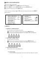
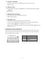
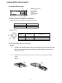
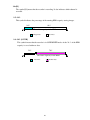
1
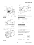
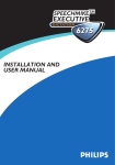
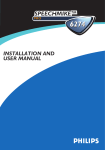
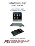
User Manual
Eye
RM-422M
Digital Video Recorder
Before attempting to connect or operate this product,
please read this manual carefully and keep it for future use.
Notice:
reserves the right to make improvements to the product
described in this manual at any time and without prior notice.
This manual is copyrighted. All rights are reserved. This manual may not be copied, reproduced or
translated in whole or part without prior consent from
.
Eye is a trademark of Signal Communications Limited and is registered in China, Hong
Kong, US and other countries.
All other trademarks are the property of their respective owners.
Copyright (c) 2004
rights reserved.
(A Member of
Eye Group). All
Version 2.0
Limits of Liability and Disclaimer of Warranty
have taken care in preparation of this manual, but makes no
expressed or implied warranty of any kind and assume no responsibility for errors or omissions. No
liability is assumed for incidental or consequential damages in connection with or arising out of the
use of the information or accessories contained herein.
Features and specifications are subject to change without prior notice.
1
CONTENTS
PREFACE --------------------------------------------------------------------------------------4
FEATURES ------------------------------------------------------------------------------------4
SPECIFICATIONS --------------------------------------------------------------------------- 5
MAJOR OPERATING CONTROLS AND THEIR FUNCTIONS
1> Front View ------------------------------------------------------------------------------ 6
2> Rear View ------------------------------------------------------------------------------- 7
3> Bottom View ---------------------------------------------------------------------------- 8
MENU AND SYSTEM SETUP
1.>MENU 1
1.1> Display Camera Select ----------------------------------------------------------- 9
1.2> Record Camera Select ------------------------------------------------------------ 9
1.3> Record Mode Select -------------------------------------------------------------- 9
1.4> Record Field Rate ----------------------------------------------------------------- 10
1.5> Record Video Quality ------------------------------------------------------------ 10
1.6> Record Schedule -------------------------------------------------------------------10
1.7> Sensor Setup
1.7.1> Post-alarm Record Time -------------------------------------------------------- 11
1.7.2> Alarm Duration ------------------------------------------------------------------ 11
1.7.3> Sensor Type Settings ------------------------------------------------------------ 11
1.8> Motion Detection Setup
1.8.1> Motion Det Camera Select------------------------------------------------------ 12
1.8.2> Motion Det Sensitivity---------------------------------------------------------- 12
1.8.3> Video Loss Camera Select-------------------------------------------------------12
1.8.4> Video Loss Alarm-----------------------------------------------------------------12
1.9> Hard Disk Drive Setup
1.9.1> Overwrite Enabled ------------------------------------------------------------- 13
1.9.2> HDD Format --------------------------------------------------------------------13
1.10> Next Page (Menu 2) ------------------------------------------------------------- 13
2.> NEXT PAGE (MENU 2)
2.1> Password Setup -------------------------------------------------------------------14
2.2> Time Setup ------------------------------------------------------------------------ 14
2.3> Language Select ------------------------------------------------------------------ 14
2.4> Key Tone -------------------------------------------------------------------------- 14
2.5> Sensor Alarm Beep -------------------------------------------------------------- 15
2.6> HDD Full Beep -------------------------------------------------------------------15
2.7> Record Message Display ----------------------------------------------------- 15
2.8> Security Lock ----------------------------------------------------------------------15
3.>SENSOR ALARM CONNECTION ---------------------------------------------------- 15
4.>HARD DRIVE INSTALLATION
4.1> Front Panel Description ------------------------------------------------------------16
4.2> Power Indicator and HDD Access Indicator ------------------------------------16
4.3> Key Lock -----------------------------------------------------------------------------16
4.4> Installing Hard Drive into Cartridge ----------------------------------------------16
5.>HARD DRIVE CONFIGURATION ---------------------------------------------------18
6.> KEY LOCK ------------------------------------------------------------------------------- 18
2
RECORDING AND PLAYBACK
1>RECORDING ------------------------------------------------------------------------------ 19
2>PLAYBACK-------------------------------------------------------------------------------- 21
TROUBLESHOOTING ------------------------------------------------------------------------ 22
3
PREFACE
Eye RM-422M is an advanced 4 channel standalone digital video recorder, with all in one
solution of video multiplexing, and digital video recording in a single easy to use and install
package.
It can be easily integrated into your existing surveillance system since it provides 2 video
composite outputs to connect CCTV monitor directly. The friendly operations avoid from wasting
time to familiarize yourself with extremely complicated DVRs.
FEATURES
1. Full Screen Recording and Playback
To record and play back high quality full screen pictures.
2. Two Recording Modes Available – DUAL mode and QUAD mode
In the DUAL mode, user can monitor live pictures or play back the recorded pictures from
single channel or all channels simutaneously. In the QUAD mode, the live pictures or the
recorded pictures are displayed in quad format only.
3. Play back at the simple touch of one button.
User just simply press the playback key twice to start playback.
4. Extend recording time through motion detection
For avoiding from unnecessary recording, users are allowed to select the cameras to be in
motion detection mode in channel by channel.
5. Key Lock
To restrict operating or changing the settings without permission.
4
SPECIFICATIONS
VIDEO INPUT
STANDARD
PAL/CCIR: 625 lines, 50 fields per second
NTSC/EIA: 525 lines, 60 fields per second
composite video, 1Vp-p, BNC, switchable
4
NO. OF CHANNELS
VIDEO OUTPUT STANDARD
PAL/CCIR: 625 lines, 50 fields per second
NTSC/EIA: 525 lines, 60 fields per second
composite video, 1Vp-p, BNC
2
NO. OF CHANNELS
RECORDING
MODE
RESOLUTION
HD TYPE
COMPRESSION FORMAT
MAX. RECORDING RATE
manual, programmable, alarm-driven, motion detection
PAL/CCIR: 720 x 576 pixels
NTSC/EIA: 720 x 480 pixels
IDE interface, removable (Max. 200GB)
MJPEG
PAL/CCIR: 50 fields per second
NTSC/EIA: 60 fields per second
PLAYBACK
SEARCH MODE
SPEED
date, time, camera
1x, 2x, 4x, 8x
ALARM
ALARM IN/OUT
input: 4x, NC/NO
output: 1x, dry contact
POWER
VOLTAGE
MAX. RATING
12V DC
30W
-10oC - 45oC
OPERATING
AMBIENT TEMPERATURE
ENVIRONMENT
RELATIVE HUMIDITY
MECHANICAL
DESIGN
< 85% ( no condensation )
DIMENSION
430mm x 265mm x 44.4mm
WEIGHT
4.7kg
Specifications are subject to change without prior notice.
5
MAJOR OPERATING CONTROLS AND THEIR FUNCTIONS
1> Front View
(a)
(b) (c) (d)(e) (f)
(g) (h) (i) (j) (k) (l)
(n) (p) (o) (m)
(a) Power Indicator
(b)
Display Channel 1 in full screen format
(c)
Display Channel 2 in full screen format
(d)
Display Channel 3 in full screen format
(e)
Display Channel 4 in full screen format
(f)
Display 4 channels in quad screen format
(g) REC
Start Recording
(h)
Playback
(i)
Pause
(j)
Rewind
(k)
Fast Forward (FF x2, FF x4, FF x8)
(l)
Stop Recording or Playing Back
(m) MENU
Enter / Exit the Menu
(n) SELECT
Select and Adjust
6
(q)
(o)
Move the > cursor up or left
(p)
Move the > cursor down or right
(q) HDD Cartridge
2> Rear View
(a) (b) (c)
(d)
(e)
(f)
(a) Cooling Fan
(b) Y/C Output
(c) Video Signal Output 1 (1Vp-p/75
)
(d) Video Signal Output 2 (1Vp-p/75
)
(e) Video Signal Input – Channel 1 – 4
(f) Video Signal Loop – Channel 1 - 4
(g) Sensor Input x 4, (NO, NC or Not Installed)
(h) Alarm Output x 1 (Relay out, NO switches to Alarm Close)
(i) DC Power Input
(j) Power ON/OFF Switch
7
(g) (h) (i)
(j)
3>Bottom View
( NTSC / PAL System SELECT )
(a)
(a) To change
NTSC / PAL System
SELECT
8
Switch.
MENU AND SYSTEM SETUP
There are two pages in setup menu.
To enter the MENU 1, press the MENU button on the front panel.
To enter MENU 2, select the NEXT PAGE and press the SELECT button.
To exit the setup menu, press the MENU button.
A cursor can be moved using the
or
button on the front panel and press the SELECT
button to choose.
>
MENU 1
DISPLAY CAMERA SELECT
RECORD CAMERA SELECT
RECORD MODE SELECT
RECORD FIELD RATE
RECORD VIDEO QUALITY
RECORD SCHEDULE
SENSOR SETUP
MOTION DET SETUP
HARD DRIVE SETUP
NEXT PAGE (MENU 2)
1234
1234
DUAL
50
HIGH
>
MENU 2
PASSWORD SETUP
TIME SETUP
LANGUAGE SELECT
KEY TONE
SENSOR ALARM BEEP
HDD FULL BEEP
RECORD MESSAGE DISPLAY
ENG/
OFF/ON
OFF/ON
OFF/ON
OFF/ON
1> MENU 1
1.1>DISPLAY CAMERA SELECT
To select cameras to be displayed on monitor.
All options can be completed in rotation by pressing the SELECT button.
User can also press the following buttons to select which cameas to be displayed.
1.2> RECORD CAMERA SELECT
To select cameras to be recorded.
All options can be completed in rotation by pressing the SELECT button.
User can also press the following buttons to select which cameas to be recorded.
1.3> RECORD MODE SELECT
The recorder provides two recording modes.
1.3.1> DUAL mode
In live monitoring or playing back, user can view full screen images of a specific
9
camera or the images of all selected cameras in quad format.
1.3.2> QUAD mode
User can view live quad format images and play back the quad format images in realtime speed.
1.4> RECORD FIELD RATE
The record field rate means how many pictures to be recorded per second. There are nine
recording rate options to select - 60(50) fields /sec, 30 fields/sec, 20 fields/sec, 14 fields/sec,
10 fields/sec, 8 fields/sec, 6 fields/sec, 4 fields/sec and 2 fields/sec.
The system field rate
Recording Rate per camera =
------------------------------------The number of cameras
1.5> RECORD VIDEO QUALITY
Select video quality. There are three quality levels selectable - HIGH, NORMAL and
LOW.
1.6> RECORD SCHEDULE
Enter RECORD SCHEDULE menu, a time schedule table shows up. The 24 segments in
the table represent 24 hours (one day). Tap the
and
buttons to move the V cursor
and press the SELECT button to set recording mode for each hour.
V
+ S S S S A A A A A A A A A A A A A A
0
3
6
9
12
15
18
21
S +
24
The three recording modes:
The symbol A means the CONTINUOUS RECORDING mode. The recorder records
continuously.
The symbol S means the SENSOR ALARM mode or MOTION DETECION mode.
recorder reacts to start. The recorder starts recording while activated by any sensor
The
connected to the recorder or by the detecting of motion .
The symbol means the NO RECORDING mode.
*Note: After press the REC button, the recorder will be controlled by the record schedule.
10
1.7> SENSOR SETUP
To enter the SENSOR SETUP menu, press the SELECT button, A sub menu will display
as follow,
>
SENSOR SETUP
POST-ALARM RECORD TIME
ALARM DURATION
CHANNEL-1
CHANNEL-2
CHANNEL-3
CHANNEL-4
30
20
TYPE: NORMAL-OPEN
TYPE: NORMAL-CLOSE
NOT INSTALLED
TYPE: NORMAL-OPEN
1.7.1> POST-ALARM RECORD TIME
When sensors are activated, they will trigger the recorder to record. As the
activated sensors stop, the recording activity will remain a period of time,
which can be adjusted by pressing the SELECT button. The options may be 5
sec 10 sec 15 sec 20 sec 25 sec and 30 sec.
1.7.2> ALARM DURATION
When any sensor connected to the recorder is activated, the recorder will react
an alarm to start the buzzer and relay. The buzzing time may be OFF 5 sec
10 sec 15 sec 20 sec 25 sec 30 sec and CONT (continuous buzzing).
*Note: If under CONT (continuous) mode, press any button on the front panel
to clear buzzer and relay out.
1.7.3> SENSOR TYPE SETTINGS
The NORMAL OPEN, NORMAL CLOSE or NOT INSTALLED is able to be set up
for each channel.
11
1.8> MOTION DETECTION SETUP
>
MOTION DET SETUP
MOTION DET CAMERA SELECT
CH-1 MOTION SENSITIVITY
CH-2 MOTION SENSITIVITY
CH-3 MOTION SENSITIVITY
CH-4 MOTION SENSITIVITY
VIDEO LOSS CAMERA SELECT
VIDEO LOSS ALARM
1234
LOW
NORMAL
HIGH
S-HIGH
1234
ON
1.8.1> MOTION DET CAMERA SELECT
To select cameras to enter or exit motion detection mode.
All options can be completed in rotation by pressing the SELECT button.
User can also press the following buttons to complete the selection.
1.8.2> MOTION DET SENSITIVITY
Select the sensitivities of motion detection. There are five sensitivity levels
selectable - S-HIGH, SUPER, HIGH, NORMAL and LOW.
1.8.3> VIDEO LOSS CAMERA SELECT
To select cameras to enter or exit Video Loss Detection Mode.
All options can be completed in rotation by pressing the SELECT button.
User can also press the following buttons to complete the selection.
1.8.4> VIDEO LOSS ALARM
ON: Under Video Loss Alarm mode, the DVR beeps when one or all of the 4
Channels lose the video signal.
OFF: No beeping.
12
1.9> HARD DRIVE SETUP
To enter the HARD DRIVE SETUP menu, press the SELECT button. A sub menu will
show as follow,
>
HARD DRIVE SETUP
OVERWRITE ENABLED
MASTER HDD SIZE
MASTER HDD USED
MASTER HDD FORMAT
YES
76319 MB
1968 MB
2%
This menu displays the capacity of hard drive, used capacity and percentage. It also allows
user to
format hard drive
set up hard drive overwrite
1. 9.1> OVERWRITE ENABLED
YES: If HDD is full, the recording continues. The recorder eventually go into
OVERWRITE mode; which means that the most updated data replaced by the
new data.
NO:
If HDD is full, the recorder stop recording.
1. 9.2> HDD FORMAT
To format the equipped HDD, user needs to enter password to format HDD formatted
automatically. The default HDD format password is “55555”.
*Note: To change password, please refer to 2.1 PASSWORD SETUP on page 10.
1.10>
NEXT PAGE (MENU 2)
>
MENU 1
NEXT PAGE (MENU 2)
Press the SELECT button to enter MENU 2.
13
2> MENU 2
Select NEXT PAGE in MENU 1 and press the SELECT button to enter MENU 2.
>
MENU 2
PASSWORD SETUP
TIME SETUP
LANGUAGE SELECT
ENG/
2.1> PASSWORD SETUP
Pressing the SELECT button to enter the sub menu is as follow.
CURRENT PASSWORD
NEW PASSWORD
PASSWORD CONFIRM
______
______
______
Press the above buttons on the front panel to enter the current password, new password
and then enter the new password again to confirm. The buttons represent the numbers
above them.
*Note: The default password is “55555”.
2.2> TIME SETUP
To enter the TIME SETUP menu which show as follow. Pressing the
or
button to
move
the cursor and tap the SELECT button to adjust date and time.
2003/ 02/ 24
TIME
10 : 23 : 45
2.3> LANGUAGE SELECT
The recorder provides the on screen menu in English and in Chinese. Press the SELECT
button to choose.
2.4> KEY TONE
ON: The DVR beeps as pushing the buttons.
OFF: No beeping.
14
2.5> SENSOR ALARM BEEP
ON: Under sensor alarm mode, the DVR beeps when it is activated to record.
OFF: No beeping.
2.6> HDD FULL BEEP
ON: The DVR will beep when the running HDD is 99% full. The beeping continues until the
HDD is full.
OFF: No beeping.
2.7> RECORD MESSAGE DISPLAY
ON: The related messages are displayed on the screen.
OFF: Not being displayed.
2.8> SECURITY LOCK
DVR allows security lock function for button on the front panel.
Press five times "||" button into security lock mode. At once under security lock mode,
monitor will display
symbol on right-upper corner of screen.
Press five times "||" button again to disable security lock mode. Meanwhile
disappear on screen.
symbol will
3> SENSOR ALARM CONNECTION
The recorder has 4 sensor input terminals on the rear panel. In the sensor alarm mode, if one of
the sensor is activated, the recorder starts to record the images from the corresponding channel.
The correspondence chart is as follow.
Sensor
S1
S2
S3
S4
15
Corresponding Channel
Channel 1
Channel 2
Channel 3
Channel 4
4> HARD DRIVE INSTALLATION
4.1> Front Panel Description
6
1
2
3
5
4
1. HDD Access Indicator
2. Power Indicator
3. Active-Handle
4. Handle
5. Cartridge Frame
6. Key Lock
4.2> Power Indicator and HDD Access Indicator
When power is turned on, the indicator will display the following
Item
Power Indicator
HDD Access Indicator
Indicator
Green LED
Amber LED
4.3> Key Lock
Status
Segment
A
B
C
Power status
Security status
ON
OFF
OFF
Locked (Non-removable)
Locked (Non-removable)
Unlocked (Removable)
4.4> Installing Hard Drive into Cartridge
Step 1
1-1. Pull the active-handle outwards and use the miniature key provided and insert into
the key hole, turning the key anti-clockwise, then the handle will auto-eject for
pulling out. (Fig.1)
1-2.
Pull the handle outwards to remove the carrier body away from the cartridge
frame.
(Fig. 2)
16
Step 2
2-1. Push the released latch to slide the top cover backwards and remove. (Fig.3)
Step 3
3-1. Insert the DC power cable and IDE cable on the HDD. (Fig.4)
3-2. Position the HDD into carrier body and secure the HDD using the four 6#-32 screws
provided. (Fig.5)
Step 4
4-1. Slide the top cover back to the carrier body by sliding forward to secure. (Fig.6)
Step 5
5-1. Slide the carrier body into the recorder and push carrier body further into cartridge
frame until it is fully inserted. (Fig.7 and Fig.8)
17
5> HARD DRIVE CONFIGURATION
The swappable hard drive installed in the recorder should be set as master drive.
For master configuration, please refer to instruction guide of HDD manufacturers. An
example is as follows ,
Power Input
40 pin Flat Cable Connector
Pins for master Settings
Refer to this chart and set the jumpers
(7-8)(5-6)(3-4)(1-2)
Limited capacity to 32 Gbytes
Master or single drive
Drive is a slave
Master with a non-ATAcompatible slave
Enable cable select
Instruction Guide
Setting Master HDD
6> KEY LOCK
To lock or unlock buttons, press the button(PAUSE) 5 times continuously.
PAUSE
18
RECORDING AND PLAYBACK
1.>RECORDING
Press the REC button in the front panel to start recording. Push the
recording.
button to stop
While in the recording mode, some symbols will be displayed on the monitor screen as
follows,
R
R
DUAL REC
CH1
CH3
[M]
(A)
CH2
CH4
CH1
CH3
R
R
2003/05/13
12:00:00
QUAD REC
[M]
CH2
CH4
(S) 2003/05/13
12:00:00
24% [OVWR]
16 %
1.1>DUAL
REC / QUAD REC
DUAL REC: In live monitoring or playing back, user can view full screen images of a
specific camera or the images of all selected cameras in quad format.
QUAD REC: User can view live quad format images and play back the quad format
images in real-time speed.
1.2>[M]
[M] : Images are recorded to master hard disk drive.
1.3> (A) / (S) / (-)
(A) : The recorder records continuously.
(S) : The recorder reacts to start recording while activated by any sensor connected
to the recorder.
(-) : No recording.
19
1.4>[R]
The symbol [R] means that the recorder is recording. It also indicates which channel is
recorded.
1.5> 16%
This symbol indicates the percentage of the running HDD capacity storing images.
16%
84%
The whole capacity of the HDD
Image Data
No Data
1.6> 24% [OVWR]
This symbol means that the recorder is in OVERWRITE mode. At the 24 % of the HDD
capacity is saved with new data.
24%
76%
The whole capacity of the HDD
New Data
Earlier Data
20
2. >PLAYBACK
To play back, Press the
button to enter playback menu.
SEARCH TIME
03/04/27
01
02
03
04
HARD DRIVE: MASTER
08:05:34 -- 03/05/12 18:27:09
--------CONT
SENSOR
SENSOR
CONT
RECORD LIST --------2003 / 05 / 12 07: 43 : 12
2003 / 05 / 12 02 : 23: 54
2003 / 05 / 12 01 : 44 : 35
2003 / 05 / 11 10: 17 : 22
:
Step 1: Select hard disk drive to play back.
Step 2: Go to the dates and times shown under hard drive option. Press the
or
button to move the cursor and press the SELECT button to set the date and
time to start playback.
OR
Press the
button to enter RECORD LIST, select a record and press the
button.
button to play back. To exit the RECORD LIST, Press the
button : Press this button to freeze picture when play back.
button : Press this button to fast forward, and press button again to adjust speed
at 2 / 4 / 8 times.
button : Press this button to fast rewind.
21
TROUBLESHOOTING
Trouble
The system restarts
automatically and
continuously.
Possible Causes
Remove the Harddisk Cartridge
when the system is Power On.
Solution
Step1: Power Off the system and remove
the Harddisk Cartridge.
Step 2: Press “STOP” continuous and
Power On at the same time. Then the
messages “ALL DATA IS INITIALIZED”,
“DVR RESET COMPLETED”, “TURN
OFF AND ON THE DVR” will be shown
on screen.
Step 3: Power Off the system and install
the Harddisk Cartridge.
Step 4: Power On again.
22