1
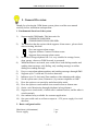
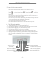
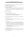
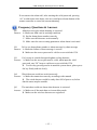
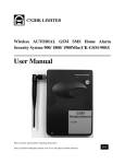
GSM Intelligent Alarm System user manual
Table Of Content
I. General overview
1. Fundamental function of the system.................................................................. 1
2. Basic kits configuration..................................................................................... 1
3. Technical Parameters: ....................................................................................... 2
II. The installation of the alarm system
1. Installation of main host.................................................................................... 3
2. Installation of door detector............................................................................... 4
3. Installation of P.I.R. .......................................................................................... 4
III. The usage of main host
1. Setting Alarm phone number ............................................................................ 5
2. Setting alarm message…………....................................................................... 6
3. Coding between main host and wireless detectors………………….………....6
4. Parameters Setting of main host........................................................................ 7
5. Usage of wireless remote controller……………………………………….....8
6. The LEDs on the main host.............................................................................. 9
IV. The basic usage guide……………................................................................ 10
V. Frequency Questions & Answers................................................................... 11
Appendix Technical parameters for wireless detectors....................................... 12
-- 1 --
GSM Intelligent Alarm System user manual
I. General Overview
Thanks for selecting the GSM alarm system, please read the user manual
carefully before installation and operation.
1. Fundamental function of the system
1)
Support multi GSM bands, This host suits for:
GSM900/DCS1800 MHz
GSM850/900/DCS1800/1900 MHz
2) The main host has the option which supports Alarm center , please check
when selecting, this host:
Does not support alarm center
Supports Ademco Contact ID alarm center
Supports short message alarm center
3) No need of fixing telephone line. It is very suitable for cottage, house,
shop, garage, wherever GSM Network is presented.
4) When the alarm is activated, user could select: both dialing number and
sending short message, only dialing, only sending message or neither
dialing nor sending message.
5) Easy to setup alarm phone numbers and sending messages through SMS.
6) Supports up to 7 wired and 28 wireless detectors.
7) Indicates up to 30 Activated Zone numbers when alarming and coding.
8) Set the system state (Arm, Disarm etc.) by remote telephone or SMS.
9) Have the option to set arm delay and alarm delay mode.
10) Have the option to send confirm siren sound in arm or disarm state.
11) Onsite voice Monitoring through telephone in long distance.
12) Support two wired sirens, of which one is onboard socket, and the other is
wired terminals.
13) One onboard relay available for customer application.
14) One port could work as collector output or +12V power supply for wired
detectors.
2. Basic configuration kits
Main host (with antenna)
Power supply
1 set
1 pc
-- 2 --
GSM Intelligent Alarm System user manual
Wireless P.I.R.
1 pc
Wireless Door detector
1 set
Remote controller
2 pcs
External siren
1 pc
User manual
1 pc
Optional: backup battery, wireless smoke detector, gas detector, infrared curtain
sensor, panic button etc.
Figure1. main host of the alarm system
3. Technical Parameters:
1)
2)
Power supply:
Static Current:
AC110V/220V ~ DC12V 1A
< 12mA(without battery charging current)
3)
GSM transmission power: CLASS4(2W)/EGSM850/900,
4)
5)
Wireless frequency:
Wireless Modulation:
6)
Wireless receive sensitivity:-95dBm@12dB SINAD
7)
8)
9)
Support defense zone:
Volume of siren:
Working temperature:
CLASS1(1W)/DCS1800/1900
433.92 MHz (or 315 MHz if specified)
ASK
35
≥110dBspl
-20℃ ~ +55℃
-- 3 --
R.H.≤90%
GSM Intelligent Alarm System user manual
II. The installation of the alarm system
1. Installation of main host
The main host should be installed firmly when there is GSM signal and power
supply, no additional wired connection needed.
1
8
2
7
3
6
4
5
Figure2. external interface in the rear of main host.
①
②
③
④
⑤
⑥
⑦
⑧
Backup battery (optional) switch, the battery could keep the system work
a few hours without external power supply.
External power supply socket, DC 12V/1A, inner Anode.
Wired siren socket.
External 12 pins interface, see Note 3.
SIM card, eject the tray by pressing the yellow button, push it back after
putting the card into the tray.
Registration press key: through which Arm Out detectors could make the
registration (coding) with the main host.
Reset/Registration press key: through which Arm Home detectors could
make the registration(coding) with the main host;
It also works as the system reset function, pressing the key when power
on, all system parameters would be set to default (factory setting).
Antenna Port, connect antenna before operation, Keep the antenna in
vertical for better performance.
-- 4 --
GSM Intelligent Alarm System user manual
Note 3: External 12 pins interface, from left to right:
Pin 1: Common ground.
Pin 2: Siren output positive, negative is connected to common ground.
Pin 3: Output terminal, or +12V power supply output selecting by one on
board jumper.
Pin 4 to Pin 10 are wired input terminals, of which each is composed of
common ground, Self adapt alarm activated, that is more than 100ms
level change in the working situation would activate the alarm.
Pin 11 and Pin 12 are the input and output terminals of onboard relay.
Closed when Relay is on, and open when it is off.
Wired
siren
Relay input
Relay output
collector output
+12V power
7 channel wired detector input
Figure3. connection of external ports
2. Installation of door detector
From the principle of Magnetic Door/Window detector: When the gap of magnet
and Magnetron is increased to a certain distance, the magnetism decreases
accordingly and the switch in the Magnetron turns on and results from alarming.
It can detect the opening of doors and windows. Magnet part is easy to be
installed on doors or windows, the other part then fixed on the door frames by
adhesive tape, the activated gap is 8 ~ 15mm.
-- 5 --
GSM Intelligent Alarm System user manual
3. Installation of P.I.R.
PIR could detect body in the certain range. Detection distance is from 5 to 12
meters (adjustable), Horizontal detection angle is 110 degrees, and vertical
detection angle is 60 degrees. Adjust the direction and distance to the suitable
Position, and then fix the PIR on the wall or the furniture. Please be noted: the
position and direction of the PIR would affect the detection performance, please
contact your suppliers if you meet difficulties when make the in installation.
III. The usage of main host
1.
Setting alarm telephone numbers
User must set alarm phone(or alarm center) numbers in SIM card by the user
name A1 to A7 before using it, when alarms activated, main host would dial the
alarm numbers from A1 to A7 and send alarm message in turn.
Save to the SIM card directly through the mobile phone:
Put the SIM card into one GSM cell phone and save alarm phone numbers in
SIM card, by the name from A1 to A7 respectively. No longer than 20 digits for
each number, no “+” needed for international numbers, no country code for
domestic numbers.
Setup through the short message
Sending short message to main host number with the format:
****#A1(A2/A3/A4/A5/A6,A7)# ########
In this manual, if there is no particular declaration,
“****” represents 4 digits access password, default is “1234”,
“#A1#” (A1-A7) represent alarm phone No., two “#” are must.
“########” represents valid 8 digits phone number,
“XXXXXXXXXX” represents text characters,
For example:
1234#A1#88888888
Setting the number “88888888” to A1
-- 6 --
GSM Intelligent Alarm System user manual
Please pay attention:
If the main host supports alarm center, then A1, A2 would be saved to Alarm
center phone numbers, and A3-A7 are 5 Alarm phone number.
2. Setting alarm messages
The alarm message is the corresponding text information(SMS) sent to user
mobile phones which preserved in the main host when this zone alarm is
activated, those messages are created by the main host by the default format
“ 1(2-35) zone activated” in the initialization process.
1 to 7 are wired zone, 8-35 are wireless zone
Also user could set the alarm message by modifying the corresponding text in
mobile phone or sending short message by the following format:
****#SM#1(2-35)XXXXXXXXXX
For example:
“1234#SM#5 wired zone is alarming”,
Then the message“5 wired zone is alarming” would save to SIM card as the
alarm message.
Note:
1) The digits 1-35 in the head of each message is the must, otherwise they
would not be corresponded to wired and wireless alarm zone numbers.
The length of each message is no more than 100 letters, the exceeded parts
would be probably missed.
2) All messages are saved into SIM card, the host would only deal with
message 1 to 18 if the messages capability of the card is 20.
3. Coding (Registration) between main host and wireless detectors
Detectors (except remote controllers and emergency detectors) would be
registered to the main host by two mode: Arm at home, and Arm Out.
In arm at Home state, the detectors registered by Arm at home mode could not
activate the alarm, such as indoor infrared detectors. In arm Out state, all the
registered detectors could activate the alarm.
Whatever state the main host in, any registered emergent detectors (Smoking
and Gas leakage detectors etc.) are activated, the main host would make the
alarm immediately.
-- 7 --
GSM Intelligent Alarm System user manual
Registration at Arm Out mode
Press “Code” key for 2s, release and then press again, after one beep, the
system is in coding (out) mode, and then user make detectors registered, after
finishing coding, Press “Code” key again, the main host ends coding process
with one beep.
Registration at Arm Home mode
press “Reset” key for 2s, release and then press again, after one beep, the
system is in coding (at home) state, and then user make detectors registered,
after finishing coding, Press “Reset” key again, the main host ends coding
process with one beep.
Remark: In coding mode, “Reset” key works as “code at home” key.
Modify the arm mode or Remove the registered detectors
User could change detectors state from arm at home (or out) to arm out(at home)
freely just by one registration out(at home) mode process.
Pressing Reset key when power on would remove all registered detector.
4.
Parameters Setting of main host
1) Set by remote telephone
User dial the main host number, after answered, input “****#”(password
and“#”, the default password is 1234) by pressing the keys of the talking phone,
after one beep, then user could make the following configuration through
pressing keys.
0#
Arm
(default)
0*
Disarm
1#
Alarm delay 35S
1*
Alarm delay 0S
2#
Enable phone call when alarming (default)
2*
Disable phone call when alarming
3#
Enable Siren make sound when the main host is in Arm/Disarm
statue
3*
Disable Arm/Disarm Siren sound (default)
4#
Relay closed
4*
Relay opened (default)
5#
Sends SMS when alarm is activated (default)
5*
Does not send SMS when alarm is activated
-- 8 --
GSM Intelligent Alarm System user manual
6#
7#
7*
8# ****#
9#
9*
Attention:
1.
2.
Release alarming, main host ends the current alarm and phone
connection.
Siren make alarm sound when alarm is activated (default)
No siren sound when alarm activated
Change to new password****
Disable onsite monitoring (default)
Enable onsite monitoring
Each operation is ended with “#”or “*”, one beep indicates one successful
action, no beep indicates the action is invalid, please check and try again.
If the main host supports the Alarm center, the following setting would be:
2#
Reports arm/disarm status to alarm center Enable (for hosts
support alarm center)
2*
Does not report the status to alarm center (default)
3# **** # Set the host ID(****) (for hosts support alarm center)
2)
Set by short message
User could Send SMS to main host number to set function with the following
format:
1)
****XXXXXXXX [,XXXXXXXX] (Content of SMS),
Set main host status, the content of SMS includes:
ARM
DISARM
RELAY ON
RELAY OFF
eg: “1234ARM, RELAY OFF”
Represents setting main host Arm, relay on (closed)
2)
Set new password to “6789”
1234#PW#6789
3)
Setting the number “13888888888” to A3 (alarm telephone).
1234#A3#138888888
4)
Setting the message“1 external input alarm” to SIM card.
1234#SM#1 external input alarm
5)
Set main host ID “0008” if the main host supports alarm center
1234#ID#0008
-- 9 --
GSM Intelligent Alarm System user manual
5. Usage of wireless remote controller
The remote controller has three buttons or four buttons: Arm out
Button
, or Arm at home button
, Disarm Button
,and Panic
Button
.
Press Arm out (or arm at home) Button, main host would be in arm out (or
arm at home) state after about 30s delay.
Press arm out (or arm at home) followed by panic button would get into arm
out (or arm at home) state immediately (instant arm).
Press Panic button would activate the alarm,
Press Disarm button would release or cancel the alarm at any time.
6. The LEDs on the main host
1) Output indicator (OUT): lit when output high level.
2) Input indicator (INPUT): lit when any of input from IN1 to IN7 activated.
3) Relay indicator (RELAY): lit when inside relay closed.
4) Siren indicator (SIREN): lit when siren is sounding.
5) Monitor indicator (MONITOR): lit when get into onsite monitor state.
6) GSM signal indicator (SIGNAL): blinked when searching GSM signal and
talk, lit in standby, extinguished if there are no signal or valid alarm phone
numbers.
Power supply led(POWER)
Output led(OUT)
Input led(IN)
Arm/disarm status (STATUS)
Relay status led(RELAY)
GSM, card status (SIGNAL)
Monitor status(MONITOR)
Siren status led(SIREN)
Figure 4. LEDs in the front panel
--- 10 --
GSM Intelligent Alarm System user manual
7) Status indicator (STATUS): lit when armed, extinguished for disarmed,
blinked for alarming and delay arm.
8) Power indicator (POWER): lit when power on.
9) Zone indicator(ZONE ID):
“8”LEDs on the top right corner of host represents the zone numbers, display
“1 - 9”and “A - F”, digit “1-7”represent external wired input zone I1 to I7,
“8-F” represents wireless zone 8-15, “1-F” with the lit point “.” represents
wireless zone 16-30.
IV. The basic usage guide
1)The installation of main host and detectors
Mount the antenna, connect the wired detectors properly, and relay if
available, input SIM card, and plug in power supply etc.
2) Set the alarm phone number and alarm message either edit SIM directly or
through short message.
3) Make wireless detectors and remote controller registration to the main host
according the above procedure.
4) Alarm Activated
A. Main host is in out arm status, any level change in the wired input
terminal I1 to I7, any wireless activated signal from registered detectors.
B. Main host is in at home arm status, any level change in the wired input
terminal I1 to I7, any wireless activated signal from arm home detectors.
C. Any emergency signal from registered detectors for example smoking
and Gas leakage detectors.
D. Pressing panic button of registered remote controller.
5)
Valid answer/release alarm
When alarm activated, the siren sounds, main host sends alarm message, and
dial alarm phone number continuously up to 5 times if there is no valid
answer or release action.
--- 11 --
GSM Intelligent Alarm System user manual
If user answer the alarm call, after entering the valid password, pressing
“6#” would release this alarm, also user could press disarm button of the
remote controller to cancel the current alarming.
Frequency Questions & Answers
Q1:
Main host can’t dial when alarming is activated
Answer: A. Make sure SIM card in working condition
B. Set the alarm phone number correctly
C. Make sure the detectors work normally
D. Make sure the correct setting parameters when alarm is activated
Q2:
Fail to set alarm phone number or alarm message by short message
Answer: A. Make the format of short message is correct.
B. Make sure the access password is valid or reset to default 1234.
Q3:
Can’t setup or control through telephone in long distance
Answer: A. Make sure the access password is valid, when input the valid
password, one “Di” beep to confirm or reset to default 1234.
B. Too fast key pressing results in unstable system detect, please press
the key firmly and not slowly.
Q4:
Wired detectors could not work incorrectly
Answer: A. Make the connection correctly according to the manual
B. The wired detector would be ready after 60S of power on, before
that the status maybe unstable.
Q5:
The main host could not alarm when detector is activated.
Answer: A. Make sure if the main host set in arm delay mode
B. Make sure the wireless detectors are registered
--- 12 --
GSM Intelligent Alarm System user manual
Appendix. Technical parameters for wireless detectors
1. Wireless gap (door/window) Detector
Power supply:
DC = 12V~8.4V(inner battery DC=12V)
Static Current:
I1 ≤ 15μA
Transmission Current:
I2 ≤ 15mA
Transmission Frequency:
f = 315/433.92 ±0.2MHz
Transmission Time:
T ≥ 1S
Transmission Distance:
No Obstacle ≥ 80m;
Internal distance:
8 ~ 15mm
Working Temperature:
-10℃~+40℃
Relative Humidity:
≤ 90%
2. Wireless P.I.R. Detector
Power supply:
Static Current:
Transmission Current:
Transmission Frequency:
Transmission Time:
Transmission Distance:
Preheating Time:
Interval of twice Emission:
Detected Distance:
Detected Angle:
Working Condition:
Relative Humidity:
Static Current:
DC = 9V~7.2V(inner battery DC=9V)
I1 ≤ 30μA
I2 ≤ 20mA
f = 433.92 (or 315)±0.2MHz
T ≥ 1s
No Obstacle ≥ 80m
≤ 2min.30s
≤ 35s
5~12m
Horizontal: 110°,Vertical: 60°
Temperature: -10℃~+40℃
≤ 90%
I1 ≤30μA
Transmission Current:
I2≤20mA
Transmission Frequency:
f=315/433.92 ±0.2MHz
3. Wireless Remote Controller
Power supply:
DC = 12V~8.4V
Static Current:
I1= 0
Transmission Current:
I2 ≤ 15mA
Transmission Frequency:
f = 315/433.92 ±0.2MHz
Transmission Time:
T ≤ 1s
Transmission Distance:
No Obstacle ≥ 80m
Working Condition:
Temperature: -10℃~ +40℃
Relative Humidity:
≤ 90%
--- 13 --