1
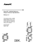
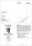
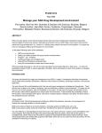
User manual PhyBUS
Digital Input/Output
Interface
BLN 99-11 UM
December 1999
Eindhoven University of Technology
Department of Physics
Physical & Technical Laboratory Automation Group
Author:
Version:
Date:
R. Smeets
1.0
10-12-1999
Hardware design:
F. Van Nijmweegen
IMPORTANT NOTICE
SWITCH OFF THE SYSTEM POWER BEFORE
INSTALLING OR REMOVING THIS INTERFACE.
IGNORING THIS ADVICE MAY RESULT IN
PERMANENT DAMAGE TO THIS INTERFACE OR
TO OTHER INTERFACES.
PhyBUS Digital Input/Output interface BLN 99-11
Technical Laboratory Automation Group
Page 1
PhyBUS Digital Input/Output interface BLN 99-11
Technical Laboratory Automation Group
Page 2
Table of contents
page
1.
Introduction . . . . . . . . . . . . . . . . . . . . . . . . . . . . . . . . . . . . . . . . . . . . . . . . . . . . . . . . 5
2.
Block diagram of the DIO interface . . . . . . . . . . . . . . . . . . . . . . . . . . . . . . . . . . . . . . 7
3.
Programming model of the DIO . . . . . . . . . . . . . . . . . . . . . . . . . . . . . . . . . . . . . . . . 9
3.1
PhyBUS Status Word Register . . . . . . . . . . . . . . . . . . . . . . . . . . . . . . . . . 10
3.2
I/O Data Register . . . . . . . . . . . . . . . . . . . . . . . . . . . . . . . . . . . . . . . . . . . . 13
3.3
Status Register . . . . . . . . . . . . . . . . . . . . . . . . . . . . . . . . . . . . . . . . . . . . . . 14
3.4
Trigger Select Register . . . . . . . . . . . . . . . . . . . . . . . . . . . . . . . . . . . . . . . 15
3.5
Interrupt Select Register . . . . . . . . . . . . . . . . . . . . . . . . . . . . . . . . . . . . . . 15
3.6
Interface Identification Register . . . . . . . . . . . . . . . . . . . . . . . . . . . . . . . . 16
4.
DIO signal description . . . . . . . . . . . . . . . . . . . . . . . . . . . . . . . . . . . . . . . . . . . . . . .
4.1
Data inputs / outputs . . . . . . . . . . . . . . . . . . . . . . . . . . . . . . . . . . . . . . . . .
4.2
Trigger input (TRIG) . . . . . . . . . . . . . . . . . . . . . . . . . . . . . . . . . . . . . . . . .
4.3
Ready For Trigger output (RFT) . . . . . . . . . . . . . . . . . . . . . . . . . . . . . . . .
PhyBUS Digital Input/Output interface BLN 99-11
Technical Laboratory Automation Group
Page 3
17
17
19
19
PhyBUS Digital Input/Output interface BLN 99-11
Technical Laboratory Automation Group
Page 4
1.
Introduction
This manual gives a description of the PhyBUS Digital Input/Output interface, BLN 99-11.
The PhyBUS Digital Input/Output interface (DIO) is used for performing 32-bit
parallel digital I/O. Each of the port I/O connections can be programmed to function as either
an input or an output. The DIO interface can operate in I/O mode or in PhyPAD mode (see
report BLN 89-04 for a description of the PhyPAD).
The main features of the PhyBUS DIO interface are:
!
one 32-bit I/O port (PhyPAD compatible)
!
each of the 32 I/O connections is programmable as either an input or an output
!
each input connection can be selected for external triggering
!
CMOS compatible I/O signal termination
!
inputs and outputs are active LOW
!
I/O connections are available through 50 pin male PhyPAD connector
PhyBUS Digital Input/Output interface BLN 99-11
Technical Laboratory Automation Group
Page 5
PhyBUS Digital Input/Output interface BLN 99-11
Technical Laboratory Automation Group
Page 6
2.
Block diagram of the DIO interface
PHYBUS
32
I/O DATA
REGISTER
PHYPAD CONTROL
STATUS
REGISTER
TRIGGER
SELECT
REGISTER
I/O
CONTROL
Figure 2.1
TRIG IN
RFT OUT
Block diagram
PhyBUS Digital Input/Output interface BLN 99-11
Technical Laboratory Automation Group
Page 7
PhyBUS Digital Input/Output interface BLN 99-11
Technical Laboratory Automation Group
Page 8
3.
Programming model of the DIO
The DIO programming model, as seen from the PhyBUS, is given in figure 3.1.
NOTE 1 :
in 16-bit PhyBUS systems, 32-bit registers are implemented as a set of two
16-bit registers at consecutive subaddresses. These register sets MUST be
accessed in the following order:
!
!
HIGH word FIRST,
LOW word SECOND.
Accessing only one register of a register set, or accessing both registers in
reverse order will result in erroneous operation!
NOTE 2 :
0x00
throughout this manual, all registers are described as if the DIO interface is
used in a 32-bit PhyBUS, except where noted otherwise.
PHYBUS STATUS WORD REGISTER
R/W
0x01
0x02
I/O DATA REGISTER
R/W
0x04
STATUS REGISTER
R/W
0x06
TRIGGER SELECT REGISTER
R/W
0x08
0x0D
0x0E
0x0F
INTERRUPT SELECT REGISTER
INTERFACE IDENTIFICATION REGISTER
Figure 3.1
R/W
RO
DIO programming model
PhyBUS Digital Input/Output interface BLN 99-11
Technical Laboratory Automation Group
Page 9
3.1
PhyBUS Status Word Register
This 16-bit read/write register at subaddress 0x00 controls the general operation of
the DIO interface.
0x00
X
X
X
X
C1S
C0S
TD0
X
DONE
IE
RST
PPE
C1M
C0M
ETE
X
15
14
13
12
11
10
9
8
7
6
5
4
3
2
1
0
Figure 3.2
PhyBUS Status Word Register
bit
mnemonic
R/W
description
15..12
11
10
9
8
7
6
5
4
3
2
1
0
C1S
C0S
TD
DONE
IE
RST
PPE
C1M
C0M
ETE
-
RO
RO
RO
RO
R/W
WO
R/W
R/W
R/W
R/W
-
not used, reads as zero
Control signal 1 Slave (PhyPAD specific)
Control signal 0 Slave (PhyPAD specific)
Trigger Detected on I/O port
not used, reads as zero
DONE
Interrupt Enable
ReSeT
PhyPAD Enable
Control signal 1 Master (PhyPAD specific)
Control signal 0 Master (PhyPAD specific)
External Trigger Enable
not used, reads as zero
C1S, C0S (bits 11, 10): Control Signal 1..0 Slave (PhyPAD specific). These bits are
the PhyPAD slave control bits, and indicate the status of the PhyPAD slave device (the DIO
interface functions as a PhyPAD master device).
The C1S and C0S bits are only valid if the PPE bit (PhyPAD Enable) is set. If the
PPE bit is cleared, the C1S and C0S bits are cleared.
For a detailed description of the PhyPAD protocol and the use of the C1S and C0S
bits, see report BLN 89-04.
PhyBUS Digital Input/Output interface BLN 99-11
Technical Laboratory Automation Group
Page 10
TD (bit 9): Trigger Detected on I/O port. This bit is set if external triggering is
enabled for the I/O port and when an external trigger occurs on the TRIG input. External
triggering for the I/O port is enabled if the ETE bit in the PhyBUS Status Word Register is
set.
When the TD bit is set, the DONE bit is also set, indicating that an external trigger
has occurred and that data from the I/O port can be read via the I/O Data Register at
subaddress 0x02.
The TD bit is set when setting the RST bit or when issuing a software PhyBUS
initialisation command. The TD bit is cleared when setting the ETE bit in the PhyBUS Status
Word Register.
The TD bit can only be used if I/O port operation is selected, i.e. the PPE bit in the
PhyBUS Status Word Register must be cleared. If PhyPAD-operation is selected (PPE bit is
set), the TD bit is always cleared.
DONE (bit 7): DONE. The DONE bit is always set if the I/O port is disabled for
external triggering, i.e. if the ETE bit is cleared.
If external triggering is enabled for the I/O port (i.e., the ETE bit is set), the DONE
bit is set when an external trigger occurs on the TRIG input. This external trigger also sets the
TD bit.
The DONE bit is cleared when setting the ETE bit. The DONE bit is set when
setting the RST bit or when issuing a software PhyBUS initialisation command.
The DONE bit can only be used if I/O port operation is selected, i.e. the PPE bit in
the PhyBUS Status Word Register must be cleared. If PhyPAD operation is selected (the PPE
bit is set), the DONE bit is always set.
IE (bit 6): Interrupt Enable. If this bit is set, a PhyBUS interrupt is generated when
the DONE bit is set. If the IE bit is cleared, no PhyBUS interrupt can be generated.
The IE bit is cleared when setting the RST bit or when issuing a software PhyBUS
initialisation command.
NOTE: make sure that the IE bit is set after the ETE bit has been set, otherwise a
PhyBUS interrupt will occur immediately (because the DONE bit has not been cleared yet).
RST (bit 5): ReSeT DIO. Setting this bit initializes the DIO interface. The TD bit
and the DONE bit in the PhyBUS Status Word Register are set, and the PPE bit is cleared.
The I/O Data Register, the Status Register, and the Trigger Select Registers are cleared (set to
0).
Setting the RST bit is a one-time command. This bit need not be cleared.
PhyBUS Digital Input/Output interface BLN 99-11
Technical Laboratory Automation Group
Page 11
PPE (bit 4): PhyPAD Enable. Setting this bit enables the DIO interface to function as
a PhyPAD master device, conforming to the PhyPAD protocol. For a detailed description of
the PhyPAD protocol, see report BLN 89-04. Clearing the PPE bit enables the DIO to
function as a 32-bit I/O port.
"
I/O port operation (PPE bit is cleared): the contents of the Status Register at
subaddress 0x04 determines which I/O pin is used as input or as output. The
PhyPAD specific control signals are not used.
"
PhyPAD operation (PPE bit is set): the RFT output on the front panel is at a
logic LOW level, and the TRIG input is discarded. The contents of the
Status Register at subaddress 0x04 is discarded. Writing the I/O Data
Register at subaddress 0x02 executes a PhyPAD write transfer, reading this
register executes a PhyPAD read transfer.
The PPE bit is cleared when setting the RST bit or when issuing a software PhyBUS
initialisation command.
C1M, C0M (bits 3, 2): Control Signal 1..0 Master (PhyPAD specific). These bits are
the PhyPAD master control bits, and are used for controlling a PhyPAD slave device (the
DIO interface functions as a PhyPAD master device).
The C1M and C0M bits are only used if PhyPAD operation is selected (PPE bit is
set). If I/O port operation is selected (PPE bit is cleared), the state of the C1M and C0M bits
are discarded.
For a detailed description of the PhyPAD protocol and the use of the C1M and C0M
bits, see report BLN 89-04.
ETE (bit 1): External Trigger Enable I/O port. Setting this bit enables external
triggering for the I/O port. The RFT output of the I/O port is set to a logic HIGH level,
indicating that the I/O port is ready to accept a trigger on the TRIG input. When an external
trigger occurs on this input, both the DONE bit and the TD bit are set, indicating that valid
input data can be read from the I/O Data Register at subaddress 0x02. If the IE bit is set, a
PhyBUS interrupt is generated.
If an I/O connection of the I/O port is defined as an input (the corresponding bit in
Status Register at subaddress 0x04 is set), and this input is enabled for external triggering (the
corresponding bit in Trigger Select Register at subaddress 0x06 is set), the data on the input
pin is clocked into I/O Data Register on a LOW to HIGH transition of the trigger signal. After
clearing the ETE bit, data can be read from the I/O Data Register.
The ETE bit can only be used if I/O port operation is selected, i.e. the PPE bit in the
PhyBUS Status Word Register must be cleared. If PhyPAD operation is selected, (PPE bit is
set), the state of the ETE bit is discarded.
PhyBUS Digital Input/Output interface BLN 99-11
Technical Laboratory Automation Group
Page 12
3.2
I/O Data Register
This 32-bit read/write registers at subaddresses 0x02 is used for reading data from
and/or writing data to an external device.
"
PhyPAD operation selected (PPE bit is in the PhyBUS Status Word Register is set):
the contents of the Status Register at subaddress 0x04 is discarded. Writing the I/O
Data Register at subaddress 0x02 executes a PhyPAD write transfer, reading this
register executes a PhyPAD read transfer.
"
I/O port operation selected (PPE bit is in the PhyBUS Status Word Register is
cleared): the contents of the Status Register at subaddress 0x04 determines whether
an I/O connection is used as an input or an output.
Reading the I/O Data Register if no external triggering is selected (the
corresponding bit in the Trigger Select Register is cleared) returns the current state
of all inputs. If an I/O connection is programmed as an output (the corresponding bit
in the Status Register is set), reading an I/O Data Register returns the value that has
been written to that output.
If external triggering is selected for an input connection (the corresponding
bit in the Trigger Select Register is set), the current state of that input connection is
copied to the I/O Data Register when an external trigger occurs on the TRIG input.
Writing an I/O Data Register sets the connections of the port that have been
programmed as an output, to the corresponding value. As the input and output
signals are active LOW, a data bit in an I/O Data Register that is set to logic 0
corresponds with an input or output voltage of app. 5 volts. A data bit that is set to
logic 1 corresponds with an input or output voltage of app. 0 volts.
PhyBUS Digital Input/Output interface BLN 99-11
Technical Laboratory Automation Group
Page 13
3.3
Status Register
This 32-bit read/write register at subaddresses 0x04 is used to select whether an I/O
connection is used as an input or an output. Clearing a bit selects an I/O connection to
function as an input. Setting a bit selects an I/O connection to function as an output.
If PhyPAD operation is selected (PPE bit is in the PhyBUS Status Word Register is
set), the contents of the Status Register is discarded.
0x04
SR31 SR30 SR29 SR28 SR27 SR26 SR25 SR24 SR23 SR22 SR21 SR20 SR19 SR18 SR17 SR16
31
0x05
30
29
28
27
26
25
24
23
22
21
20
19
18
17
16
SR15 SR14 SR13 SR12 SR11 SR10 SR09 SR08 SR07 SR06 SR05 SR04 SR03 SR02 SR01 SR00
15
14
Figure 3.3
13
12
11
10
9
8
7
6
5
4
3
2
1
0
Status Register
The Status Register is cleared when setting the RST bit or when issuing a software
PhyBUS initialisation command, i.e. all I/O connections are selected to function as an input.
PhyBUS Digital Input/Output interface BLN 99-11
Technical Laboratory Automation Group
Page 14
3.4
Trigger Select Register
This 32-bit read/write register at subaddresses 0x06 is used to determine whether an
I/O connection, that has been programmed as an input pin, is used in external trigger mode.
If PhyPAD operation is selected (PPE bit is in the PhyBUS Status Word Register is
set), the contents of the Trigger Select Register is discarded.
0x06
TS31 TS30 TS29 TS28 TS27 TS26 TS25 TS24 TS23 TS22 TS21 TS20 TS19 TS18 TS17 TS16
31
0x07
30
29
28
27
26
25
24
23
22
21
20
19
18
17
16
TS15 TS14 TS13 TS12 TS11 TS10 TS09 TS08 TS07 TS06 TS05 TS04 TS03 TS02 TS01 TS00
15
14
13
12
Figure 3.4
11
10
9
8
7
6
5
4
3
2
1
0
Trigger Select Register
In external trigger mode, the data on the input pin is clocked into the input register
when a LOW to HIGH transition occurs on the TRIG input. Input data can be read using the
I/O Data Register.
Setting a bit in the Trigger Select Register enables the corresponding input pin for
external trigger operation. Clearing a bit in Trigger Select Register disables the corresponding
input pin for external trigger operation.
The Trigger Select Register is cleared when setting the RST bit or when issuing a
software PhyBUS initialisation command, i.e. all input pins are disabled for external trigger
operation.
3.5
Interrupt Select Register
This 16-bit read/write register at subaddress 0x0e is used to select the PhyBUS
interrupt bit for the DIO. PhyBUS interrupt bits 15..0 can be selected. Only bits 3..0 of this
register are used.
0x0E
X
X
X
X
X
X
X
X
X
X
X
X
IS3
IS2
IS1
IS0
15
14
13
12
11
10
9
8
7
6
5
4
3
2
1
0
Figure 3.5
Interrupt Select Register
PhyBUS Digital Input/Output interface BLN 99-11
Technical Laboratory Automation Group
Page 15
3.6
Interface Identification Register
This 16-bit read-only register at subaddress 0x0f holds a value that uniquely
determines the PhyBUS interface type. Bits 15..4 hold the identification code of the interface.
For the DIO, the identification code contained in bits 15..4 is 0x40 (64 decimal). The lower 4
bits of this register (bits 3..0) hold the revision code of the DIO. Writing this register results
in a bus error.
0x0F
INTERFACE IDENTIFICATION CODE
15
14
Figure 3.6
13
12
11
10
9
8
7
REVISION CODE
6
5
4
Interface Identification Register
PhyBUS Digital Input/Output interface BLN 99-11
Technical Laboratory Automation Group
Page 16
3
2
1
0
4.
DIO signal description
4.1
Data inputs / outputs
The data inputs and data outputs are available through a 50-pin male connector. The
connections are given in figure 4.1. Note that all data inputs and outputs (pins labeled Dxx)
are active LOW !
Data inputs and data outputs are terminated as shown in figure 4.2.
The following control signals are specific for PhyPAD operation, and can be left open for I/O
port operation:
signal name
I/O
pin number
C1M*
C0M*
C1S*
C0S*
WRITE*
SYNC*
ACK*
O
O
I
I
O
O
I
32
33
30
31
34
27
26
Table 4.1
PhyPAD specific control signals
PhyBUS Digital Input/Output interface BLN 99-11
Technical Laboratory Automation Group
Page 17
MALE CONNECTOR
FRONT VIEW
D00*
50
49
D01*
D02*
48
47
D03*
D04*
46
45
D05*
D06*
44
43
D07*
D08*
42
41
D09*
D10*
40
39
D11*
D12*
38
37
D13*
D14*
36
35
D15*
WRITE*
34
33
C0M*
C1M*
32
31
C0S*
C1S*
30
29
GND
28
27
SYNC*
ACK*
26
25
D16*
D17*
24
23
D18*
D19*
22
21
D20*
D21*
20
19
D22*
D23*
17
D24*
D25*
18
16
15
D26*
D27*
14
13
D28*
D29*
12
11
D30*
D31*
10
9
8
7
GND
6
5
GND
4
3
GND
2
1
GND
Figure 4.1
I/O connector pin assignment
+5V
330 E
74F125
I/O
470 E
EPLD
(CMOS INPUT)
Figure 4.2
I/O pin termination
PhyBUS Digital Input/Output interface BLN 99-11
Technical Laboratory Automation Group
Page 18
4.2
Trigger input (TRIG)
The TRIG input has the following specifications:
.
.
.
.
.
.
.
available through female CAMAC connector
Schmitt trigger input
input impedance 50 ohm
minimum input pulse width: 20 ns
TTL compatible signal levels
positive edge-triggered (LOW to HIGH transition)
input is not protected against overvoltages
4.3
Ready For Trigger output (RFT)
These outputs are used to indicate to an external device that the DIO is ready to
accept a (new) trigger on the TRIG input.
The RFT output is only used if I/O port operation is selected (PPE bit in the PhyBUS
Status Word Register is cleared). If PhyPAD operation is selected (PPE bit is set), the RFT
output is always at a logic LOW level.
If the RFT output is at a LOW level, the DIO is NOT ready to accept a trigger on the
TRIG input. If the RFT output is at a HIGH level, the DIO is ready to accept a trigger on the
TRIG input.
The RFT output is at a LOW level (NOT ready for trigger) if a trigger has occurred
on the TRIG input, and the data has not been read from the I/O Data Register. Reading data
from the I/O Data Register will cause the RFT output to go to a HIGH level again.
The RFT output has the following specifications:
.
.
.
.
.
available through female CAMAC connector
output impedance 50 ohm
TTL compatible signal levels
active HIGH
output is not short-circuit protected
PhyBUS Digital Input/Output interface BLN 99-11
Technical Laboratory Automation Group
Page 19