1
2 SYSTEM CONFIGURATION
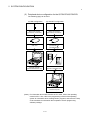
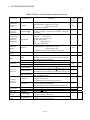
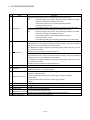
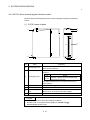
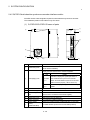
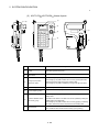
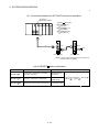
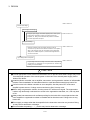
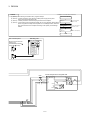
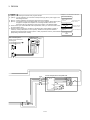
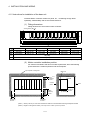
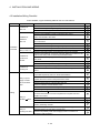
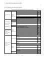
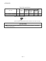
No.
Name
Application
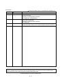
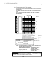
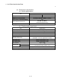
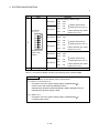
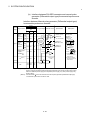
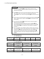
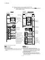
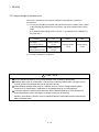
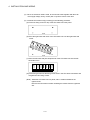
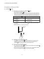
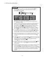
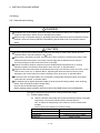
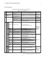
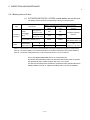
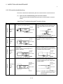
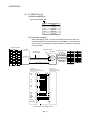
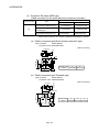
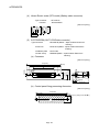
Detection setting of TREN1 signal
Dip switch 1
Dip switch 2
Dip switches
(Note-1)(Note-2)
ON
1 2 3 4 5 6
6)
SW1
SW2
OFF
OFF
ON
ON
ON
OFF
OFF
ON
Dip switch 3
Dip switch 4
Dip switch 5
Dip switch 6
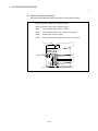
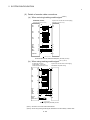
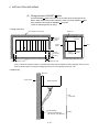
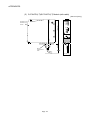
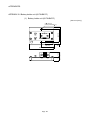
Module fixing hook
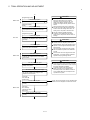
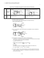
TREN is detected when TREN
signal turns on to off.
SW3
SW4
OFF
OFF
ON
ON
ON
OFF
OFF
ON
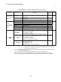
TREN is detected when
TREN signal turns off to on.
TREN is detected when TREN
signal turns on to off.
Detection setting of TREN3 signal
factory in OFF
7)
TREN signal turns off to on.
Detection setting of TREN2 signal
(Shipped from the
position)
TREN is detected when
SW5
SW6
OFF
OFF
ON
ON
ON
OFF
OFF
ON
TREN is detected when
TREN signal turns off to on.
TREN is detected when TREN
signal turns on to off.
Hook used to fix to the base unit.
(Note-1) : When using the Q173PX-S1 only.
(Note-2) : The function is different according to the operating system software installed.
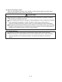
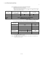
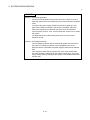
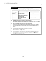
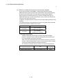
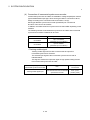
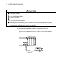
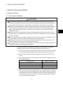
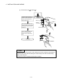
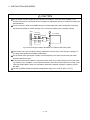
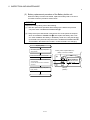
POINTS
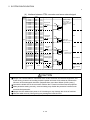
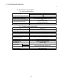
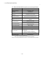
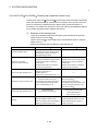
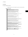
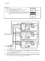
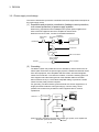
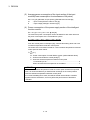
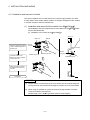
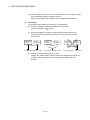
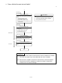
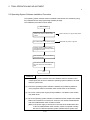
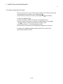
The lighting condition of input display LED is shown below.
(1) PLS.A 1 to 3, PLS.B 1 to 3
• Q173PX is set on the system setting display of SW6RN-GSV P.
• All axes servo ON command (M2042) turned on.
• Manual pulse generator enable flag (M2051, M2052, M2053) turned on.
• Manual pulse generator signal is input.
(2) TREN 1 to 3
• Q173PX is set on the system setting display of SW6RN-GSV P.
• Tracking signal is input.
2 - 56