1
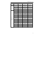
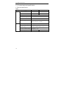
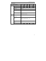
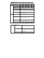
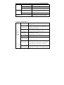
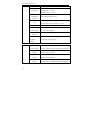
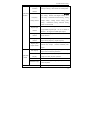
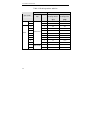
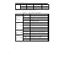
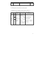
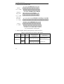
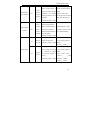
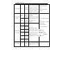
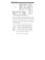
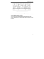
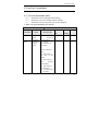
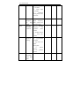
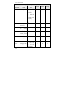
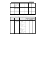
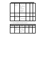
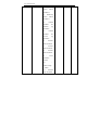
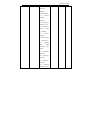
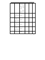
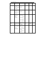
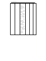
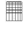
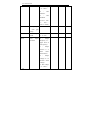
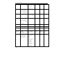
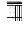
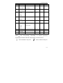
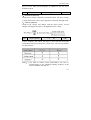
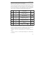
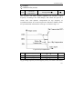
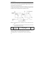
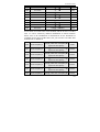
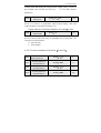
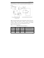
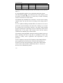
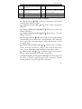
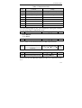
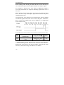
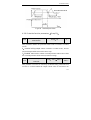
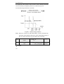
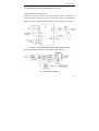
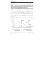
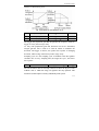
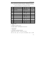
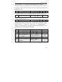
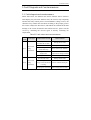
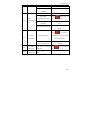
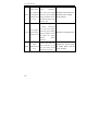
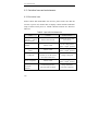
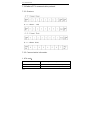
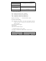
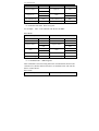
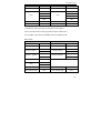
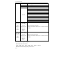
V5 series inverter
7
Output frequency arrive upper
18
Stop braking time
limit(FH)
8
Output frequency arrive lower
limit(FL)
19
9
Inverter zero speed running
20
10
Simple PLC Pause running
21
High and lower limits of traverse
operating frequency
set running time arriving
Instructions of the functions shown in Tabel 4-6:
0:Inverter running(RUN). Inverter is in the running status and the
terminal outputs indication signal.
1:Frequency arriving signal(FAR). Refer to P4.12 for function
instruction.
2:Frequency detection threshold(FDT1). Refer to P4.11~ P4.12 for
function instruction.
3:Frequency detection threshold(FDT2). Refer to P4.13~P4.14 for
function instruction.
4:Overload pre-alarm(OL). If the output current is higher than the
value defined by P4.24 and the time is longer than the value defined by
P4.25, the inverter will output indicate signals. This function is mainly
used in pre-alarm.
5:Inverter under voltage locking(LU). While inverter is in running
process, if the DC injection bus voltage is lower than the limit value,
“E-11” will be displayed in LED and indicate signal will be output.
6:External fault stop(EXT). An indicate signal will be output if
inverter outputs trigging signal caused by external fault.
7:Output frequency arrive upper limit(FH). An indicate signal will
be output if reference frequency≥upper limit of frequency and the
running frequency arrives the upper limit of frequency.
161