1
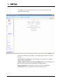
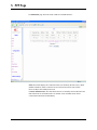
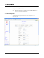
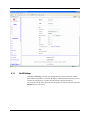
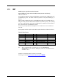
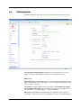
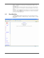
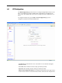
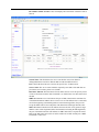
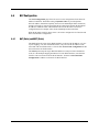
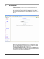
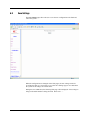
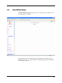
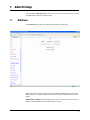
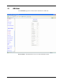
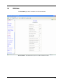
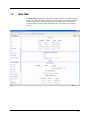
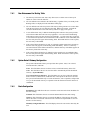
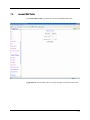
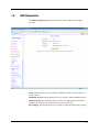
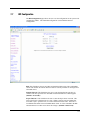
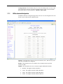
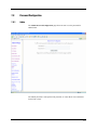
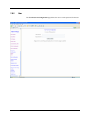
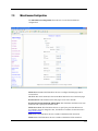
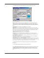
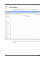
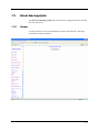
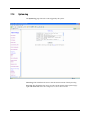
User Guide
Version: 1.2
Contents
1. System Requirements ...........................................................................................................................1-1
2. Login.......................................................................................................................................................2-1
3. Status....................................................................................................................................................3-1
3.1
3.2
Home Page ..................................................................................................................................................................... 3-1
ADSL Status Page........................................................................................................................................................... 3-3
4. LAN Page..............................................................................................................................................4-1
5. PPP Page..............................................................................................................................................5-1
6. Configuration Pages .............................................................................................................................6-1
6.1
6.2
6.3
6.4
6.5
6.6
6.7
6.8
6.9
WAN Configuration ......................................................................................................................................................... 6-1
6.1.1
Per VC Settings .............................................................................................................................................. 6-2
6.1.2
MAC Spoofing ................................................................................................................................................ 6-3
6.1.3
ATM ................................................................................................................................................................ 6-3
6.1.4
Encapsulation, Bridge, PPP, and DHCP Client................................................................................................ 6-3
6.1.4.1 PPP Configuration .......................................................................................................................... 6-4
6.1.5
IGMP .............................................................................................................................................................. 6-5
LAN Configuration .......................................................................................................................................................... 6-6
6.2.1
Ethernet Mode Setting.................................................................................................................................... 6-7
PPP Configuration .......................................................................................................................................................... 6-8
NAT Configuration ........................................................................................................................................................ 6-11
6.4.1
NAT (Static) and NAPT (Static) .................................................................................................................... 6-11
Virtual Server Configuration ......................................................................................................................................... 6-14
Bridge Filtering ............................................................................................................................................................. 6-16
DNS Configuration........................................................................................................................................................ 6-17
Save Settings................................................................................................................................................................ 6-19
Reboot Without Saving................................................................................................................................................. 6-22
7. Admin Privilege ....................................................................................................................................7-1
7.1
7.2
7.3
7.4
7.5
7.6
7.7
7.8
7.9
7.10
7.11
7.12
7.13
7.14
WAN Status .................................................................................................................................................................... 7-1
ATM Status ..................................................................................................................................................................... 7-2
TCP Status ...................................................................................................................................................................... 7-3
Route Table..................................................................................................................................................................... 7-4
7.4.1
New Enhancement for Routing Table ............................................................................................................. 7-5
7.4.2
System Default Gateway Configuration .......................................................................................................... 7-5
7.4.3
Route Configuration ....................................................................................................................................... 7-5
Learned MAC Table......................................................................................................................................................... 7-6
ADSL Configuration ........................................................................................................................................................ 7-7
RIP Configuration ........................................................................................................................................................... 7-8
7.7.1
RIP Per Interface Configuraiton...................................................................................................................... 7-9
Password Configuration ............................................................................................................................................... 7-11
7.8.1
Admin ........................................................................................................................................................... 7-11
7.8.2
User .............................................................................................................................................................. 7-12
Miscellaneous Configuration ........................................................................................................................................ 7-13
Reset to Factory Default ............................................................................................................................................... 7-15
Diagnostic Test ............................................................................................................................................................. 7-16
Code Image Update ...................................................................................................................................................... 7-18
Network Code Image Update ........................................................................................................................................ 7-19
7.13.1
Firmware....................................................................................................................................................... 7-19
7.13.2
Boot Code..................................................................................................................................................... 7-20
System Log................................................................................................................................................................... 7-21
1. System Requirements
•
Computer
− PC and MAC
− 32 MB RAM minimum
− 20 MB of free disk space minimum
− Ethernet Network Interface Controller (NIC) RJ45 Port
− USB Port
− Internet Browser
1-1
2.
Login
1.
Launch the Web browser.
2.
Enter the LAN port default IP address http://10.0.0.2
3.
Entry of the username and password will be prompted. Enter the default login User
Name and Password.
•
The default login User Name of the administrator is admin, and the default login
Password is epicrouter.
The default login User Name for the non-administrator is user, and the default login
Password is password.
•
2-1
3.
Status
The links under the Status column are associated to the pages that represent the status of
system and interfaces.
3.1
Home Page
The Home page shows the firmware versions and WAN and LAN interface status.
Firmware Version: This field displays the firmware (vxworks.z) version
number.
3-1
Customer Software Version: This field displays the customer’s own firmware version
number and it is based on revision.txt.
WAN: These fields display the IP address, Subnet Mask and MAC address for the WAN
(ADSL) interface.
LAN: These fields display the IP address, Subnet Mask and MAC address for the LAN
interface.
Total Number of LAN Interfaces: This field displays the total number of available
interfaces for the LAN interface.
Number of Ethernet Devices Connected to the DHCP Server: These fields display the
DHCP client table with the assigned IP addresses and MAC addresses.
3-2
3.2
ADSL Status Page
The ADSL Status page shows the ADSL physical layer status.
Showtime Firmware Version: This field displays the ADSL data pump
firmware version number.
ADSL Line Status: This field displays the ADSL connection process and status.
ADSL Modulation: This field displays the ADSL modulation status for G.dmt or
T1.413.
ADSL Annex Mode: This field displays the ADSL annex modes for Annex A or
Annex B.
ADSL Startup Attempts: This field displays the ADSL connection attempts after loss of
showtime.
ADSL Max Tx Power: This field displays the transmit output power level of the CPE.
ADSL CO Vendor: This field displays the Central Office DSLAM vendor name, if
available.
3-3
Elapsed Time: This field displays the time of the modem has been in operation.
SNR Margin: Amount of increased noise that can be tolerated while maintaining the
designed BER (bit error rate). The SNR Margin is set by Central Office DSLAM. If the
SNR Margin is increased, bit error rate performance will improve, but the data rate will
decrease. Conversely, if the SNR Margin is decreased, bit error rate performance will
decrease, but the data rate will increase.
Line Attenuation: Attenuation is the decrease in magnitude of the ADSL line signal
between the transmitter (Central Office DSLAM) and the receiver (Client ADSL
Modem), measured in dB. It is measured by calculating the difference in dB between the
signal power level received at the Client ADSL modem and the reference signal power
level transmitted from the Central Office DSLAM.
Errored Seconds: The error during Showtime, whenever, a given sec contains CRC
error, that second will be declared error second.
Loss of Signal: This field displays the count of event of ADSL signal loss.
Loss of Frame: This field displays the count of event of ADSL frame loss.
CRC Errors: This field displays the number of transmit data frames containing CRC
errors.
Data Rate: This field displays the ADSL data rate.
Latency: This field displays the latency modes for fast or interleave.
3-4
4. LAN Page
The LAN page shows the information and status of LAN port, DHCP client table,
Ethernet link and USB link.
LAN: These fields display the IP address, Subnet Mask and MAC address for the LAN
interface.
Total Number of LAN Interfaces: This field displays the total number of available
interfaces for the LAN interface.
Number of Ethernet Devices Connected to the DHCP Server: These fields display the
DHCP client table with the assigned IP addresses and MAC addresses.
Ethernet Link Status: This field displays the link up or down for the Ethernet.
USB Link Status: This field displays the link up or down for the USB.
4-1
5. PPP Page
The PPP Status page shows the status of PPP for each PPP interface.
PPP: These fields display the Connection Name (user defined), Interface (PVC), Mode
(PPPoE or PPPoA), Status (Connected or Not Connected), Packets Sent, Packets
Received, Bytes Sent and Byte Received.
Connect and Disconnect: This field allows the user to manually connect/disconnect the
PPP connection for each PPP interface. In another word, each PPP session can be
connected and disconnected individually.
5-1
6. Configuration
The links under Configuration column are associated to the pages that represent the
configurations of system and interfaces.
Note:
When the configurations are changed, please go to the Save Settings page to
save the new setting and reboot the board.
6.1 WAN Configuration
The WAN configuration page allows the user to set the configuration for the
WAN/ADSL ports.
6-1
6.1.1
Per VC Settings
Under Per VC Setting, it provides the configurations for VPI/VCI, Static IP Address
Subnet Mask, and Gateway. The Static IP Address, Subnet Mask and Gateway are used
for Static IP configuration. Current Conexant firmware supports eight PVCs.
To switch between the PVCs, please choose the options of virtual circuit and click on the
Submit button to switch over.
6-2
6.1.2
MAC Spoofing
The MAC Spoofing is developed to solve the scenario when the ISP only recognizes one
MAC address. Copy the ISP-recognized MAC address here.
6.1.3
ATM
Service Category: UBR and CBR are supported from the ATM.
Bandwidth: Bandwidth setting takes effect only when the CBR is selected. The
maximum available bandwidth is from the upstream data rate of ADSL status page (see
Section 3.2, ADSL ).
6.1.4
Encapsulation, Bridge, PPP, and DHCP Client
Use Table 6-1 to configure a valid setting for each PVC.
Table 6-1. Configuration
WAN Configuration
Bridge Mode
Router Mode (PPPoA/PPPoE)
IP address
Subnet Mask
Encapsulation
N/A
N/A
1483 Bridged IP LLC,
1483 Bridged IP VC-Mux
Automatically assigned by ISP
Automatically assigned by ISP
PPPoA LLC/VC-Mux,
PPPoE LLC/VC-Mux
Bridge
PPP Service
PPP User name
PPP Password
DHCP Client enable
Enabled
N/A
N/A
N/A
Unchecked
Disabled
Provided by ISP
Provided by ISP
Provided by ISP
Unchecked
Router Mode
(Dynamic IP)
Automatically assigned by ISP
Automatically assigned by ISP
1483 Bridged/Routed IP LLC,
1483 Bridged/Routed VC-Mux,
Classical IP over ATM
Disabled
N/A
N/A
N/A
Checked
Router Mode
(Static IP)
Provided by ISP
Provided by ISP
1483 Bridged/Routed IP LLC,
1483 Bridged/Routed VC-Mux,
Classical IP over ATM
Disabled
N/A
N/A
N/A
Unchecked
6-3
6.1.4.1
PPP Configuration
The current release supports multiple PPP sessions per PVC. The PPP configuration in
the WAN configuration page is for the first PPP session for each PVC. The predefined
PPP Account Name (Account ID) is “Simple PPP Account 0” for PVC0 and predefined
PPP Connection Name is “Simple PPP Session 0” for PVC0. For the other PVC X, the
predefined account name and connection name will be Simple PPP Account X and
Simple PPP Session X. X is the PVC number from 1 to 7.
It can support up to total of 16 PPP sessions, and each PVC can support up to 8 PPP
sessions. The multiple PPP sessions may be configured with any combination over 8
PVCs.
For the multiple PPP sessions, please go to PPP Configuration page (Section 6.3).
Service Name: The service name of PPP is required by some ISPs. If the ISP does not
provide the Service Name, please leave it blank.
Disconnect Timeout: The Disconnect Timeout allows the user to set the specific period
of time to disconnect from the ISP. The default is 0, which means never disconnect from
the ISP.
MRU: Maximum Receive Unit indicates the peer of PPP connection the maximum size
of the PPP information field this device can be received. The default value is 1492 and is
used in the beginning of the PPP negotiation. In the normal negotiation, the peer will
accept this MRU and will not send packet with information field larger than this value.
MTU: Maximum Transmission Unit indicates the network stack of any packet is larger
than this value will be fragmented before the transmission. During the PPP negotiation,
the peer of the PPP connection will indicates its MRU and will be accepted. The actual
MTU of the PPP connection will be set to the smaller one of MTU and the peer’s MRU.
The default is value 1492.
MSS: Maximum Segment Size is the largest size of data that TCP will send in a single IP
packet. When a connection is established between a LAN client and a host in the WAN
side, the LAN client and the WAN host will indicate their MSS during the TCP
connection handshake. The default value is 1432.
Automatic Reconnect: When it is checked, it will maintain the PPP connection all the
time. If the ISP shut down the PPP connection, it will automatically reconnect PPP
session.
Authentication: When AUTO option is chosen, the PAP mode will run first then CHAP.
Host name: Required by some ISPs. If the ISP does not provide the Host name, please
leave it blank.
Q1: If the PPP is disconnected after the Disconnect Timeout and how can I reconnect it?
A: You have to go to the PPP Status under Admin Privileged column, choose the
correct PVC and Connect option, and then click Execute to restart a new PPP secession.
6-4
6.1.5
IGMP
IGMP relay/proxy specification and environment:
Support IGMP proxy/relay function for ADSL modem, based on the following
requirement and case:
On CO side, there must be at least one IGMP querier (router) present. IGMP querier will
send IGMP query packet. The ADSL modem is responsible to relay these IGMP query to
Ethernet.
End-user multicast application device send IGMP report while receiving IGMP query or
being activated by user, the ADSL modem should be responsible to proxy (that is, change
source IP to ADSL modem’s WAN IP) the IGMP report to ADSL WAN side, include all
PVCs. The same case is for IGMP leave packet.
Not necessary to relay multicast routing between two ADSL PVCs or two interfaces in
LAN side.
Special purpose multicast packet (such as RIP 2 packet) should run without interference.
Table 6-2. Packet Process
Rx Entity
ADSL
Ethernet
Note:
Packet Class
IGMP query
IGMP report
IGMP leave
General Multicast IP
IGMP query
IGMP report
IGMP leave
General Multicast IP
TTL
1
1
1
1
1
1
-
Action
Relay to Ethernet
Ignore
Ignore
Relay it to Ethernet.
Ignore
Relay to all ADSL PVC
Relay to all ADSL PVC
Ignore
Notes
Before the IGMP mode is enabled; please go to the Miscellaneous
Configuration page to enable the IGMP proxy. Otherwise, the IGMP selection
will not be valid.
Q: Where can I download the free software to test IGMP.
A: Please go to this link http://manimac.itd.nrl.navy.mil/MGEN/.
6-5
6.2
LAN Configuration
The LAN configuration page allows the user to set the configuration for the LAN port.
LAN IP Address & Subnet Mask: The default is 10.0.0.2 and 255.0.0.0. User can
change it to other private IP address, such as 192.168.1.2, and 255.255.255.0.
DHCP Server
System Allocated: The DHCP address pool is based on LAN port IP address plus 12 IP
addresses. For example, the LAN IP address is 10.0.0.2; the DHCP address pool is at the
range of 10.0.0.3 to 10.0.0.14.
User Defined: The DHCP address pool is at the range of User Defined Start Address
and User Defined End Address. The maximum pool size can be 253 IP addresses: 255
total IP addresses – 1 broadcast address – 1 LAN port IP address.
DHCP Gateway Selection: The default setting for the DHCP Gateway Selection is
“Automatic”. The user can select the “User Defined” to specify “User Defined Gateway
6-6
Address”. The DHCP server will issue the “User Defined Gateway Address” to the
LAN DHCP clients.
Lease time: The Lease time is the amount of time of a network user will be allowed to
connect with DHCP server. If all fields are 0, the allocated IP addresses will be effective
forever.
User mode: Under the Single User mode, the DHCP server only allocates one IP address
to local PC. Under the Multiple User mode, the DHCP server allocates the IP addresses
specified bye the DHCP address pool.
6.2.1
Ethernet Mode Setting
The Ethernet Mode configuration page allows the user to set the LAN port into Auto
Sense, 100 Mbps Full Duplex, 100 Mbps Half Duplex, 10 Mbps Full Duplex or 10 Mbps
Half Duplex.
6-7
6.3
PPP Configuration
The PPP Configuration page allows the user to configure multiple PPP sessions for each
PVC. It can support up to total of 16 PPP sessions, and each PVC can support up to 8
PPP sessions. The multiple PPP sessions may be configured with any combination over 8
PVCs.
To configure the PPP, must go to the PPP Account Configuration page first to
configure Account ID, Users Name and Password.
Account ID: This field allows the user to enter his/her own account ID to distinguish
different accounts.
User Name: Enter the PPP user name (usually provided buy the ISP).
Password: Enter the PPP password (usually provided buy the ISP).
PPP Account Configuration Status will be displayed at the bottom of this page to show
all the accounts with its Account Name and User Name. (It does not show the password.)
6-8
The Number of PPP Accounts: This field displays the total number of PPP Accounts is
entered.
Session Name: This field allows the user to enter his/her own session Name to
distinguish different session for different PPP accounts and different PVCs.
PVC: This field allows the user to choose the specific PVC for PPP session.
Service Name: The service name of PPP is required by some ISPs. If the ISP does not
provide the Service Name, please leave it blank.
Disconnect Timeout: The Disconnect Timeout allows the user to set the specific period
of time to disconnect from the ISP. The default is 0, which means never disconnect from
the ISP.
MRU: Maximum Receive Unit indicates the peer of PPP connection the maximum size
of the PPP information field this device can be received. The default value is 1492 and is
used in the beginning of the PPP negotiation. In the normal negotiation, the peer will
accept this MRU and will not send packet with information field larger than this value.
MTU: Maximum Transmission Unit indicates the network stack of any packet is larger
than this value will be fragmented before the transmission. During the PPP negotiation,
the peer of the PPP connection will indicates its MRU and will be accepted. The actual
MTU of the PPP connection will be set to the smaller one of MTU and the peer’s MRU.
The default is value 1492.
6-9
MSS: Maximum Segment Size is the largest size of data that TCP will send in a single IP
packet. When a connection is established between a LAN client and a host in the WAN
side, the LAN client and the WAN host will indicate their MSS during the TCP
connection handshake. The default value is 1432.
Automatic Reconnect: When it is checked, it will maintain the PPP connection all the
time. If the ISP shut down the PPP connection, it will automatically reconnect PPP
session.
Authentication: When AUTO option is chosen, the PAP mode will run first then CHAP.
PPP Configuration Status will be displayed at the bottom of this page to show all the
Session Names with its Adapter (PVC number), Mode (PPPoA or PPPoE), Service
Name, Account to Use (PPP Account ID), Disconnect Timeout configuration, MRU,
MTU, MSS, Authentication Mode (Auto, CHAP or PAP), and Auto Reconnect
configuration.
6-10
6.4
NAT Configuration
The NAT Configuration page allows the user to set the configuration for the Network
Address Translation. The default setting is Dynamic NAPT. It provides dynamic
Network Address Translation capability between LAN and multiple WAN connections,
and the LAN traffic is routed to appropriate WAN connections based on the destination
IP addresses and Route Table. This eliminates the need for the static NAT session
configuration between multiple LAN clients and multiple WAN connections.
When the Dynamic NAPT is chosen, there is no need to configure the NAT Session and
NAT Session Name Configuration.
6.4.1
NAT (Static) and NAPT (Static)
The NAT option only maps single WAN IP address to the local PC IP address. It is peerto-peer mapping. (1x1) For each WAN interface, only one local PC IP address can be
associated with each WAN interface. Click the link Session Name Configuration to add
the session name for WAN interface.
The NAPT option maps the single WAN IP addresses to many local PCs IP addresses.
(1xN). It is the multiple-mapping mechanism. For each WAN Interface, more than one
local PCs can be associated with one WAN Interface. Click the link Session Name
Configuration to add the session name for WAN interface.
6-11
Session Name: This field allows the user to enter his/her own session Name to
distinguish different NAT session for different interfaces among different PPP sessions
and different PVCs.
Interface: This field allows the user to choose specific WAN Interface (PVC or PPP
Session) for NAT Session.
NAT Session Name Status: This table displays at the bottom of this page to show all
the NAT Session Names with its WAN Interface.
Number of NAT Configurations: This filed displays the total number of NAT Sessions
Name is entered.
Click the link Go back to NAT Configuration to the NAT configuration page. Select
the NAT option. Select the Session Name and assign the PC IP address, and choose the
Add action. Click the Submit button and go to the Save Settings to save this
configuration.
NAT allows only one entry (User IP) per session.
NAPT allows many entries (User IPs) per session.
6-12
Session Name: This field allows the user to select the session from the configured NAT
Session Name Configuration.
User’s IP: This filed allows the user to assign the IP address to map the corresponding
NAT/NAPT sessions.
Session Name Status will be displayed at the middle of this page to show the
corresponding Session Name with its IP address.
Number of NAT Configurations: This filed displays the total number of NAT Sessions
is entered.
Available Sessions Status will be displayed at the end of this page to show all the
Session Names with its WAN Interface.
Number of Session: This filed displays the total number of NAT Sessions Name is
entered.
6-13
6.5
Virtual Server Configuration
The Virtual Server Configuration page allows the user to set the configuration of
Virtual Server. The Conexant firmware includes the Free BSD version firewall. All
UDP/TCP ports are protected from intrusion. If any specific local PCs need to be mapped
to the UDP/TCP port on WAN side, please input the mappings here.
Public Port: This field allows the user to enter the port number of the Public Network.
Private Port: This field allows the user to enter the port number of the Private Network.
In most cases, the private port number is same as public port number.
6-14
Host IP Address: This field allows the user to enter the private network IP address for
the particular sever.
Well Known Ports:
Port
21
23
25
43
53
69
70
79
80
110
115
161
162
Protocol
FTP
Telnet
SMTP
Whois
DNS
TFTP
Gopher
Finger
HTTP
POP3
SFTP
SNMP
SNMP traps
6-15
6.6
Bridge Filtering
The Bridge Filtering configuration page allows the user to set the configuration of IP
filtering.
Source MAC: When the bridge filtering is enabled, enter the Source MAC address,
select Block and click Add. Then all incoming WAN and LAN Ethernet packets matched
with this source MAC address will be filtered out. If the Forward is selected, then the
packets will be forwarded to the destination PC.
Destination MAC: When the bridge filtering is enabled, enter the Destination MAC
address, select Block and click Add. Then all incoming WAN and LAN Ethernet
packets matched with this destination MAC address will be filtered out. If the Forward
is selected, then the packets will be forwarded to the destination PC.
Type: Enter the hexadecimal number for the Ethernet type field in Ethernet_II packets.
For example, 0800 is for IP protocol.
6-16
6.7
DNS Configuration
The DNS Configuration page allows the user to set the configuration of DNS proxy.
The Conexant firmware supports the DNS proxy function. For the DHCP requests from
local PCs, the DHCP server will set the LAN port IP as the default DNS server. Thus, all
DNS query messages will come into LAN port first. The DNS proxy on the ADSL
modem recorded the available DNS servers, and forward DNS query messages to one of
DNS server.
Disable DNS Proxy: The LAN port does not process the DNS query message. For the
DHCP requests from local PCs, the DHCP server will set the user-configured preferred
DNS sever or alternate DNS server whichever is available as the DNS server. Then all
DNS query messages will be directly sent to the DNS servers.
Use Auto Discovered DNS Servers Only: The DNS proxy will store the DNS server IP
addresses obtained from DHCP client or PPP into the table. And all DNS query messages
will be sent to one of the dynamically obtained DNS servers.
6-17
Use User Configured DNS Servers Only: The DNS proxy will use the user-configured
preferred DNS server and alternate DNS server. And all DNS query message will be sent
to one of DNS servers. Enter the DNS IP in the Preferred DNS Server and Alternate DNS
Server fields.
Auto Discovery + User Configured: The DNS proxy’s table has all the IP addresses of
dynamically obtained and user configured DNS servers.
6-18
6.8
Save Settings
The Save Settings page allows the user to save the new configuration to the flash and
reboot the system.
When the configurations are changed via the Web pages, the new settings need to be
saved into the flash, so it is necessary to go to this Save Settings page to save and reboot
the system for the changes to be taken effect.
During the Save and Reboot, the following Web page will be displayed “Your setting are
being saved and the modem is being rebooted. Please wait….”
6-19
After the Save and Reboot, the following Web page will be displayed “Your setting have
been saved and the modem has rebooted.”
6-20
6-21
6.9
Reboot Without Saving
The Reboot Without Saving page allows the user to reboot the system without save the
new configuration to the flash.
During the Reboot, the following Web page will be displayed “The modem is being
rebooted. Please wait….”. After the Reboot, the following Web page will be displayed
“The modem has rebooted.”
6-22
6-23
6-24
7.
Admin Privilege
The links under Admin Privilege are only to be accessed and configured, when it is login
with administrator login name and password.
7.1
WAN Status
The WAN Status page shows the information and status of WAN PVCs.
WAN: These fields display the IP address, Subnet Mask and MAC address for the WAN
(ADSL) interface. Use the Virtual Circuit selection to selection different PVC for status
display.
DHCP Release and Renew: This field allows the user to release and renew the WAN IP
address in the WAN DHCP Client Enabled (dynamic) mode.
7-1
7.2
ATM Status
The ATM Status page shows all the statistics information of ATM cells.
Reset Counters: This button allows user to reset the ATM Status counter.
7-2
7.3
TCP Status
The TCP Status page shows the statistics for all TCP connections.
Reset Counters: This button allows user to reset the TCP Status counter.
7-3
7.4
Route Table
The Route Table page displays routing table and allows the user to manually enter the
routing entry. The routing table will display the routing status of Destination, Netmask,
Gateway, and Interface. The interface br0 means the USB interface; lo0 means the
loopback interface; and ppp1 means the PPP interface. The Gateway is the learned
Gateway
7-4
7.4.1
7.4.2
New Enhancement for Routing Table
•
The Gateway field of the static route entry allows users to either enter a Gateway IP
address or select a Network Interface.
•
All user-defined routes retained in the CPE memory, regardless if they are already in the
Routing Table, are displayed on the same Route Table page.
•
All user defined route entries kept in the CPE memory during run time are saved to flash
when the user chooses to save and reboot the CPE. When CPE restarts, it reloads all
saved user-defined routes to the CPE memory and tries to apply to the system.
•
A user-defined route entry is added to the Routing Table whenever the system provides
an environment that makes the route entry applicable. It is removed from the Routing
Table whenever the route entry becomes not applicable. e.g. If the route entry’s Gateway
is associated with a dynamic Network Interface but the connection is not established, then
the route entry does not appear in the Routing Table. When that interface comes up later,
the route entry is then added.
•
If the selected Network Interface is static or is dynamic and the connection is already up,
then the route entry appears in the Routing Table immediately. If there is a Gateway
associated with the selected Network Interface, then that Gateway’s IP address appears in
the Gateway field of the route entry
•
If the selected Network Interface is dynamic but the connection is not established, then
the route entry does not appear in the Routing Table. When the interface comes up later,
the route entry is then added.
System Default Gateway Configuration
The system-wide Default Gateway now provides three options: Auto, User-selected
Network Interface, and None.
None: This field allows the user to choose to have no Default Gateway in the CPE
Auto: This field allows the user to select the CPE to automatically decide the Default
Gateway. (System Default)
User-selected Network Interface: This field allows user to select a Network Interface
from a list (PVCs, PPP Sessions, USB and LAN). This option lets the user to associate
the system-wide Default Gateway to a Network Interface, static or dynamic, and provides
a way to fix the Default Gateway to a dynamic Network Interface before the interface is
established.
7.4.3
Route Configuration
Destination: This field allows the user to enter the remote network or host IP address for
the static routing.
Netmask: This field allows the user to enter the Subnet Mask for the static routing.
Gateway: This field allows the user to enter the IP address of the gateway device that
allows the router to contact the remote network or the host for Specified IP or select an
Interface for the Gateway.
Manually Configured Routes: This field displays the static route entries entered by the
user.
7-5
7.5
Learned MAC Table
The Learned MAC Table page shows the current learned Bridge MAC table.
Aging Timeout: This field allows the user to enter the update period for the MAC table.
7-6
7.6
ADSL Configuration
The ADSL Configuration page allows the user to set the configuration for ADSL
protocols.
Trellis: This field allows the user to enable or disable the Trellis Code. By default, it is
always enabled.
Handshake Protocol: This field allows the user to select the ADSL handshake protocol.
Wiring Selection: This field allows the user to enter the wiring selection for the RJ-11.
Tip/Rip is the default for the board without the inner/outer pair relay
Bit Swapping: This field allows the user to enable or disable the upstream bit swapping.
7-7
7.7
RIP Configuration
The RIP Configuration page allows the user to set the configuration for the system wide
configuration of RIP. The actual RIP configuration is in the RIP Per Interface
Configuration.
RIP: This field allows the user to Enable or Disable the RIP session. The resulting RIP
session will monitor all network interfaces that are currently available for messages from
other RIP routers.
Supplier Interval: This field allows the user to enter the Supplier Interval timer in
second. This timer specifies how often RIP sends announcements as a RIP Supplier.
(Default = 30 seconds)
Expire Timeout: This field allows the user to enter the Expire timer in second. This
timer specifies the expiration time of a route. When a route has not been updated for
more than “expire” period of time, it is removed from the Route Table. This route is
invalidated and remains in the internal RIP Route Table. It will be included in the RIP
announcements to let other routers know the changes. (Default = 180 seconds)
7-8
Garbage Timeout: This field allows the user to enter the Garbage timer in second. This
timer specifies how long the expired and invalidated routes are kept in the Internal RIP
Route Table before it is removed from it. (Default = 300 seconds)
7.7.1
RIP Per Interface Configuraiton
The RIP Per Interface Configuration page allows the user to set the configuration for each
Interface (PVCs, PPP Sessions, USB and LAN).
Interface: This field allows the user to choose the Interface (PVCs, PPP Sessions, USB
and LAN), for the RIP to be configured.
Enable: This field allows the user to Enable (Yes) or Disable (No) the specified
interface for RIP.
Supplier: This field allows the user to select the Supplier Mode (RIP Transmit).
•
Disabled: The supplier transmit is disabled.
•
V1 BC: The supplier transmits in RIPv1 Broadcast.
•
V2 BC: The supplier transmits in RIPv2 Broadcast.
•
V2 MC: The supplier transmits in RIPv2 Multicast.
7-9
Listener: This field allows the user to select the Listener Mode (RIP Receive)
•
V1: The listener receives the RIPv1 only.
•
V2: The listener receives the RIPv2 only.
•
V1+V2: This listener receives the both RIPv1 and RIPv2.
Supplier and Listener are based on section 4.1 “Compatibility Switch” in RFC 1723.
Current RIP Settings: This field displays the each interface’s RIP status.
7-10
7.8
Password Configuration
7.8.1
Admin
The Admin Password Configuration page allows the user to set the password for
administrator.
The Admin password is same pas the FTP password, so it must has at least 8-characters
for the FTP to work.
7-11
7.8.2
User
The User Password Configuration page allows the user to set the password for the user.
7-12
7.9
Miscellaneous Configuration
The Miscellaneous Configuration allows the user to set all the miscellaneous
configurations.
HTTP Server Access: This field allows the user to configure the Web pages can be
accessed from.
All: When this field is checked, it allows both WAN and LAN access to the Web pages.
Restricted LAN: This field allows the Web pages access from LAN side.
Restricted WAN Specified IP & Subnet Mask: This field allows the Web access from
WAN side with a specify IP and subnet mask.
HTTP Server Port: This field allows the user to specify the port of the Web access. .
For example, when it is changed to 1001, the HTTP server address for the LAN side is
http://10.0.0.2:1001.
FTP server: This field allows the user to enable or disable the FTP connection.
TFTP server: This field allows the user to enable or disable the TFTP connection.
7-13
An example for the TFTP client updating the vxworks.z product image code is:
DMZ: A DMZ (De-Militarized Zone) is added between a protected network and an
external network, in order to provide an additional layer of security. When there is a
suspected packet coming from WAN, the firewall will forward this packet to the DMZ
host.
DMZ Host IP: The IP address of the DMZ host at LAN side.
DHCP Relay: If it is enabled, the DHCP requests from local PCs will forward to the
DHCP server runs on WAN side. To have this function working properly, please disable
the NAT to run on router mode only, disable the DHCP server on the LAN port, and
make sure the routing table has the correct routing entry.
DHCP Target IP: The DHCP server runs on WAN side.
IGMP Proxy: Here is the global setting for IGMP Proxy. If it is enabled, then the
enabled IGMP Proxy on WAN PVCs will be working. Otherwise, no WAN PVC can
have IGMP Proxy working on it.
PPP connect on WAN access: If it is enabled, the PPP session will be automatically
established when there is a packet wants to go out the WAN.
PPP Half Bridge: When the PPP Half Bridge is enabled, only one PC is able to access
the Internet, and the DHCP server will duplicate the WAN IP address from the ISP to the
local client PC. Only the PC with the WAN IP address can access the Internet.
Q: What is the difference between PPP connect on WAN access and the Automatic
Reconnect?
A: Some ISPs terminated the PPP session due to the inactivity.
For the PPP connect on WAN access, the PPP will be automatically reconnected when
an URL is entered in the browser (packet interested in going out the WAN). For the
Automatic Reconnect, it will reconnect the PPP session whenever it is terminated by
ISP.
7-14
7.10
Reset to Factory Default
The Reset to Factory Default page allows the user to reset the modem to original factory
default configuration (factory.reg).
7-15
7.11
Diagnostic Test
The Diagnostic Test page shows the test results for the connectivity of the physical layer
and protocol layer for both LAN and WAN sides.
Testing Ethernet LAN Connection: This test checks the Ethernet LAN interface
connection.
Testing ADSL Synchronization: This test checks the ADSL showtime. If this test
returns FAIL, all other tests will be skipped.
Test ATM OAM Segment Loop Back: This test sends ATM OAM F5 Segment loop
back request cells to the CO. This test will pass if response cell is received. Since some
service providers might not support this test, it could still work even if this test fails. If
this test fails consistently and the ADSL modem seems not working, make sure the VPI
and VCI are configured correctly.
7-16
Test ATM OAM End-to-End Loop Back: This test sends ATM OAM F5 End to End
loop back request cells to the CO. This test will pass if response cell is received. Since
some r service providers might not support this test, it could still work even if this test
fails. If this test return FAIL consistently and the ADSL modem seems not working,
make sure the VPI and VCI are configured correctly.
Test Ethernet Connect to ATM: This test checks the ATM AAL5 module is loaded
correctly.
Test PPPoE Connection: This test checks the PPPOE connection.
Test PPP Layer Connection: This test checks the PPP authentication.
Test IP Connect to PPP: This test checks a valid IP address assigned from the service
provider.
Ping Primary DNS: This test checks the primary DNS can be reached through ping
request.
Query DNS for www.conexant.com: This test checks the host name can be resolved to
IP address though domain name servers
Ping www.conexant.com: This test checks the specified host can be reached through
ping request.
7-17
7.12
Code Image Update
The Code Image Update page allows the user to upgrade the image code locally.
Browse the location of file, firmware.dlf or boorom.dlf file, and click the Upload to start
the update.
7-18
7.13
Network Code Image Update
The Network Code Image Update page allows the user to upgrade the image code from
the remote FTP server.
7.13.1
Firmware
Assume an FTP server stores the updated image firmware.dlf on Internet. Click Image
Download to initiate the updating..
7-19
7.13.2
Boot Code
Assume an FTP server stores the updated image boorom.dlf on Internet. Click Image
Download to initiate the updating..
7-20
7.14
System Log
The System Log page shows the events triggered by the system.
Clear Log: This field allows the user to clear the current contents of the System Log.
Save Log: This field allows the user to save the current contents of the System Log by
right click HERE and select “Save Target As” to save it into a text file.
7-21
The System Log records:
•
•
•
•
DSL Layer
−
DSL Link detected
−
DSL Link connected
−
DSL Link disconnected
ATM Layer
−
ATM detected
−
ATM connected
−
ATM disconnected
−
ATM setting up VPI/VCI
PPP Layer
−
PPP authenticated
−
PPP invalid user name or password
−
PPP unable to connect with PPP server
IP Layer
−
IP protocol up
−
PPP IP address
−
PPP Gateway IP address PPP DNS Primary IP address
−
PPP DSN Secondary IP address
7-22