1
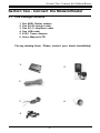
Hurricane 9000
1 -port ADSL Modem/Router
U ser's Manual
Version 2.0
1
Contents
Section One: Introduction .........................................................
4
1.1 System Requirements.............................................. 4
1.2 Features Summary .................................................. 4
Section Two: Connect the Modem/Router............................... 6
2.1 This Package Contents............................................. 6
2.2 Product View............................................................ 7
2.3 Hardware Installation...............................................
8
2.4 Network Connections .............................................. 9
2.5 LED Indicators ......................................................... 9
Section Three: Configure the PCs ............................................ 10
3.1 Configure your PC .................................................. 10
3.2 V erify the link between your PC and Router ........... 11
Section Four: Web-Based Management .................................... 13
4.1 Login ........................................................................ 13
4.2 Setup Hurricane 9000............................................... 14
4.3 Status and Advanced settings .................................. 16
4.3.1 WAN/LAN Status ........................................... 16
4.3.2 PPP Status ..................................................... 16
4.3.3 ADSL Status ..................................................... 17
4.3.4 LAN Configuration .......................................... 18
4.3.5 PPP Configuration ......................................... 19
4.3.6 NAT Configuration ......................................... 20
4.3.7 Virtual Server ............................................. 21
4.3.8 Bridge Filtering ............................................... 22
4.3.9 DNS Configuration ......................................... 23
4.3.10 ADSL Configuration .................................... 24
4.3.11 Route Table .............................................. 24
4.3.12 Learned MAc Table ...................................... 25
4.3.13 RIP Configuration ......................................... 25
4.3.14 MISC Configuration ...................................... 27
4.3.15 Admin Password ......................................... 29
4.3.16 System Log .................................................. 29
4.3.17 Firmware Update ......................................... 30
Section Five: USB Driver Installation .......................................... 31
Section Six: Troubleshouting and FAQs .................................. 32
Prolink Technical Support ............................................................. 36
2
The information contained in this manual has been verified at the time
of this manual's printing. The manufacturer reserves the right to make
any changes and improvements in the product described in this
manual at any time and without notice.
All registered trademarks are the property of their respective owners.
Copyright © 2004 All rights reserved. No reproduction of this document in any form is permitted without prior written authorization from
the manufacturer.
Important Notice
For not unlimited users, please remember to switch
off the router when the internet is not in use, OR
set "Disconenct Timeout" on the router.
3
Section One: Introduction
Section One - Introduction
The Hurricane 9000 provides Full rate (ANSI and G.DMT) as well
as G.lite ADSL standards line support, and can be connected to
PC through Ethernet or USB . This product supports bridge
feature set for the integration of ADSL service into corporate or
home LAN and WAN.
1.1 System Requirements
Before connecting the Hurricane 9000 to your PC, make
sure your sysytem is equipped with the Ethernet NIC card or USB
port and TCP/IP protocol.
1 .2 Features Summary
ADSL Compliance
Compliant with ADSL standards:
ANSI T1.413 Issue 2, ITU G.dmt (G.992.1) and G.lite (G.992.2).
ADSL over POTS (Annex A) and ADSL over ISDN (Annex B)
DMT modulation and demodulation
Full-rate adaptive modem
Maximum downstream rate of 8 Mbps
Maximum upstream rate of 1 Mbps
Tone detection for low power mode
Supports splitterless ADSL implementation
Supports Dying Gasp (optional)
ATM Protocols
WAN mode support: PPP over ATM and over Ethernet. (RFC 2364/2516)
LAN mode support: bridged/routed Ethernet over ATM (RFC 1483) and
Classical IP over ATM (RFC 1577)
ATM Forum UNI 3.1/4.0 PVC
Up to 8 VCs (Virtual Circuits)
ATM SAR (Segmentation and Reassembly)
ATM AAL5 (Adaption Layer type 5)
OAM F4/F5
4
Section One: Introduction
Bridge Mode
Ethernet to ADSL self-learning Transparent Bridging (IEEE 802.1D)
Supports up to 128 MAC learning addresses·
Router Mode
IP routingñRIPv2
Static routing
DHCP (Dynamic Host Configuration Protocol) Server and Client
NAPT (Network Address and Port Translation)
NAT (Network Address Translation)
ICMP (Internet Control Message Protocol)
Simultaneous USB and Ethernet operation·
Security
User authentication for PPP
PAP (Password Authentication Protocol)
CHAP (Challenge Authentication Protocol)
Password protected system management
Ethernet interface
Compliant with IEEE 802.3 standard
10/100 Mbps auto selection
1 x LAN port (Cable Type Auto-detecting)
USB host interface
Compliant with USB Specification, Revision 1.1
USB full speed (12 Mbps)
Vendor specific descriptors
HTTP Web-based management
Firmware upgrade via FTP
Customizable Web pages
WAN and LAN side connection statistics
Configuration of static routes and Routing table
Configuration of NAT/NAPT
Password protected access
Selection of Bridge or Router Mode
PPP user ID and password
Configuration of VCs (Virtual Circuits)
5
Section Two: Connect the Modem/Router
Section Two - Connect the Modem/Router
2.1 This Package contents
1.
2.
3.
4.
5.
6.
One ADSL Router modem
One RJ-45 straight cable
One RJ-11 telephone cable
One USB cable
9/12V Power Adaptor
User's Manual & CD
For any missing items, Please contact your dealer immediately.
1.
5
2
3
6
4
6
Section Two: Connect the Modem/Router
2.2 Product View
LAN LED TX/RX LED
LINK LED
Power Switch
POWER LED
RJ11 Line Jack
Reset Button
(Set to factory Default)
Power Connector
USB Connector
RJ45 LAN Jack
7
Section Two: Connect the Modem/Router
2.3 Hardware Installation
The following steps instruct you to install the Hurricane 9000 for
one computer. For more than one computer, please refer to 2.4
Network Connection.
1. Plug the end of the Ethernet cable into the LAN Jack of the Hurricane
9000.
2. Plug the other end of the Ethernet cable into your computer’s RJ45
Jack of Ethernet card.
3. Connect the Power adaptor to the Power Connector.
4. Plug the telephone cable into the Line Jack .
5. Plug the other end of the telephone cable into
i) a Main Socket .
ii) OR the Jack of the two-way Microfilter labeled DSL.
Telephone
2-way
Main Socket
Microfilter
ADSL Line
RJ-45
OR
USB Cable
(Optional)
Power Adaptor
Computer
8
Section Two: Connect the Modem/Router
2.4 Network Connections
2.4.1 for One PC
RJ-45
RJ-11
ADSL
or USB Cable
2.4.2 for more than one PC
ADSL
HUB/Switch
RJ-11
RJ-45
......
2.5 LED Indicators
The ADSL Router modem features LED indicators on the front panel that
report modem status:
POWER Red
LINK
Green
TX/RX
Green
LAN
Green
Power Light / Steady when power is on.
WAN Link / Steady during ADSL line status is
showtime.
WAN Activity / Blinking when transmitting/receiving
data.
LAN Link / Blinking during LAN Activity.
9
Section There: Configure the PCs
Section Three - Configure the PCs
3.1 Configure your PC.
The instructions in this section will help you to configure each
computer to communicate with the Router.
To do this, you need to configure your PC’s network settings to
obtain an IP address automatically from the DHCP of the router.
Computers use IP addresses to communicate with each other
across a network, such as the Internet.
For Windows 98/ME
1. Go to the Network screen by clicking the Start button. Click
Settings and then Control Panel. From there, double-click the
Network icon.
2. On the Configuration tab, select the TCP/IP line for the
applicable Ethernet adapter. Then, click the Properties button.
3. Click the IP Address
tab. Select Obtain an IP
address automatically.
4. Click the Gateway tab,
and verify that the
Installed Gateway field
is blank. Click the OK
button.
5. Click the OK button
again. Click the Yes
button to restart your
computer.
10
Section There: Configure the PCs
For Windows XP/2k
1. Go to the Network screen by clicking the Start button. Click
Control Panel. From there, double-click the Network Connections
icon.
2. Under LAN or Hight-Speed Internet, Right-Click Local Area
Connection icon, select Properties.
3. Select Internet Protocol (TCP/IP), click Properties.
4. Select Obtain an IP address automatically, click OK
5. Click the OK button again.
11
Section There: Configure the PCs
3.2 Verify the link between your PC and Router
a) From start > Run
b) Enter ping 10.0.0.2 –t and click OK
c) If the connection has been established, You will
receive reply from the router.
d) If you receive “Request timed out”, that means
the link has not been established, pls. check the
network cable and IP address. (or try to restart
your PC)
Notes:
1. Under MS-DOS mode, you can type ipconfig to check your
IP address. (to renew IP: ipconfig /renew )
2. You may have to disable the proxy settings on your Internet
browser .
Tools>Internet Options>Connection>LAN
settings>Disable Proxy Server
3. Make sure that your browser is set to connect directly .
For Internet Explorer, click Tools, Internet Options, and then the
Connection tab. Make sure that Internet Explorer is set to Never
dial a connection.
For Netscape Navigator, click Edit, Preferences, Advanced, and
Proxy. Make sure that Netscape Navigator is set to Direct
connection to the Internet.
12
Section Four: Web-Based Management
Section Four
Web-Based Management
4.1. Login
1)
2)
Open Internet Explorer /Netscape , type http://10.0.0.2
The system will ask for administrator’s username and
password when restarting or configuring. It is illustrated
in the following figure.
Default username: admin
password: password
13
Section Four: Web-Based Management
4.2 Setup Hurricane 9000
Click WAN under configuration, Slect Adapter: PVC0, press Submit
Button.
14
Section Four: Web-Based Management
Encapsulation: PPPoA, PPPoE, 1483 router, IPoA and 1483 Bridge.
Please selct one according to your local ISP designation.
(e.g. Singapore/Indonesia: PPPoA VCMUX; Malaysia/Thailand:
PPPoE LLC)
VPI/VCI: ATM VC of local ADSL Internet Service Provider.
(e.g. Singapore: VPI/VCI=0/100; Malaysia: VPI/VCI=0/35; Indonesia: VPI/
VCI=1/33; SriLanKa: VPI/VCI=8/35; Thailand: VPI/VCI=1/32)
Username and Password: the user name and password will be
provided by your ISP when applying for PPP ADSL service.
You can leave others settings by default.
Press Submit button, then Click Save Configuration, select Save and
Reboot.
Disconnect Timeout: The Disconnect Timeout allows users to set the
specific period of time to disconnect from the ISP. The default is 0, which
means never disconnect from the ISP.
Static WAN IP Configuration (Optional)
If you are using 1483 Routed IP or Classical IP over ATM, please enter the
IP address, Subnet Mask and Gateway (Provided by your local ISP)
15
Section Four: Web-Based Management
4.3 Status and Advanced Settings
4.3.1 WAN/LAN Status.
The WAN/LAN Status page shows the WAN , LAN interface status.
4.3.2 PPP Status.
The PPP Status page shows the status of PPP for each PVC Connect
and Disconnect allows users to manually connect/disconnect the PPP
connection for one PVC.
16
Section Four: Web-Based Management
4.3.3 ADSL Status.
The ADSL Status page shows the ADSL physical layer status.
17
Section Four: Web-Based Management
4.3.4 LAN Configuration.
The LAN page allows user to set the configuration for the LAN port.
IP Address/Subnet: LAN address and subnet mask of the router. It
can be specified if you need. (e.g. 192.168.0.1/255.255.255.0)
DHCP Server
System Allocated: The DHCP address pool is based on LAN port IP
address plus 12 IP addresses. For example, the LAN IP address is
10.0.0.2; the DHCP address pool is at the range of 10.0.0.3 to 10.0.0.14
User Defined: The DHCP address pool is at the range of User Defined
Start Address and User Defined End Address Address. The maximum
pool size can be 253 IP addresses: 255 total IP addresses - 1 broadcast
address - 1 LAN port IP address.
Lease time: The Lease time is the amount of time of a network user will
be allowed to connect with DHCP server. If all fields are 0, the allocated
IP addresses will be effective forever.
User mode: Under the Single User mode, the DHCP server only
allocates one IP address to local PC. Under the Multiple User mode, the
DHCP server allocates the IP addresses spececified bye the DHCP
address pool.
18
Section Four: Web-Based Management
4.3.5 PPP Configuration
The ppp page allows user to set the sesstion name for PVCs.
Showtime Firmware Version: This field displays the Conexant ADSL data
pump firmware version number.
ADSL Line Status: This field displays the ADSL connection process and
status.
ADSL Modulation: This field displays the ADSL modulation status for
G.dmt or T1.413.
ADSL Annex Mode: This field displays the ADSL annex modes for Annex
A or Annex B.
ADSL Startup Attempts: This field displays the ADSL connection attempts
after loss of showtime.
ADSL Max Tx Power: This field displays the transmit output power level of
the CPE.
ADSL CO Vendor: This field displays the Central Office DSLAM vendor
name, if available.
Elapsed Time: This field displays the time of the modem has been in
operation.
SNR Margin: Amount of increased noise that can be tolerated while
maintaining the designed BER (bit error rate). The SNR Margin is set by
Central Office DSLAM. If the SNR Margin is increased, bit error rate
performance will improve, but the data rate will decrease. Conversely, if
the SNR Margin is decreased, bit error rate performance will decrease, but
the data rate will increase.
Line Attenuation: Attenuation is the decrease in magnitude of the ADSL
line signal between the transmitter (Central Office DSLAM) and the
receiver (Client ADSL Modem), measured in dB. It is measured by
calculating the difference in dB between the signal power level received at
the Client ADSL modem and the reference signal power level transmitted
from the Central Office DSLAM.
19
Section Four: Web-Based Management
4.3.6 NAT Configuration
The NAT page allows users to set the configuration for the Network
Address Translation.
NAT Configuration
The NAT option only maps single WAN IP address to the local PC IP
address. It is peer-to-peer mapping. (1x1) For each PVC, only one local PC
IP address can be associated with each WAN PVC. Click the link Session
Name Configuration to add the session name for each PVC.
Q: Since only one PVC is mapped to one local PC IP address, why can I
input more than one IP address for one NAT session?
A: Even though you can, only the first IP address of each session takes effect.
NAPT Configuration
The NAPT option maps the IP address and UDP/TCP port ID of the WAN
PVC to the IP address and UDP/TCP port ID of the local PCs. (1xN). It is the
multiple-mapping mechanism. More than one local PC can be associated
with one WAN PVC.
Dynamic NAPT:The default setting is Dynamic NAPT. It provides dynamic
Network Address Translation capability between LAN and multiple WAN
connections, and the LAN traffic is routed to appropriate WAN
connections based on the destination IP addresses and Route Table. This
eliminates the need for the static NAT session configuration between
multiple LAN clients and multiple WAN connections. When the Dynamic
NAPT is chosen, there is no need to configure the NAT Session and NAT
Session Name Configuration.
20
Section Four: Web-Based Management
4.3.7 Virtual Server
The Virtual Server (Port Forwarding) page allows users to set the
configuration of Virtual Server. If any specific local PCs need to be
mapped to the UDP/TCP port on WAN side, please input the mappings
here.
For Example,
If you want to forward FTP to your 10.0.0.20 server (set to static IP):
Public Port Start: 21, Public Port End: 21, Private Port: 21 Port Type: TCP
Host IP Address: 10.0.0.20
Customized
Application
Port
TCP
UDP
Web server
FTP server
SMTP (outgoing)
POP3 (incoming)
80
21
25
110
Yes
Yes
Yes
Yes
Yes
No
Yes
Yes
21
Section Four: Web-Based Management
4.3.8 Bridge Filtering
The Bridge Filtering page allows users to set the configuration of IP
filtering.
Source MAC: When the bridge filtering is enabled, enter the Source MAC
address, select Block and click Add. Then all incoming WAN and LAN
Ethernet packets matched with this source MAC address will be filtered out.
If the Forward is selected, then the packets will be forwarded to the
destination PC.
Destination MAC: When the bridge filtering is enabled, enter the
Destination MAC address, select Block and click Add. Then all incoming
WAN and LAN Ethernet packets matched with this destination MAC address
will be filtered out. If the Forward is selected, then the packets will be
forwarded to the destination PC.
Type: Enter the hexadecimal number for the Ethernet type field in
Ethernet_II packets.
For example,
If you want to block MAC address: 000002fa6fab to access the internet:
Source MAC: 000002fa6fab Type: 0800
Remark: to check your PC's MAC address, ipconfig /all under DOS mode.
Type 0800: Internet Protocol, for others, pls. check with your administrator.
22
Section Four: Web-Based Management
4.3.9 DNS Configuration
The DNS Configuration page allows users to set the configuration
of DNS proxy. It supports the DNS proxy function. For the DHCP
requests from local PCs, the DHCP server will set the LAN port IP as
the default DNS server. Thus, all DNS query messages will come into
LAN port first. The DNS proxy on the ADSL modem recorded the
available DNS servers, and forward DNS query messages to one of DNS
server.
Disable DNS Proxy: The LAN port does not process the DNS query
message. For the DHCP requests from local PCs, the DHCP server will
set the user-configured preferred DNS sever or alternate DNS server
whichever is available as the DNS server. Then all DNS query messages
will be directly sent to the DNS servers.
Use Auto Discovered DNS Servers Only: The DNS proxy will store
the DNS server IP addresses obtained from DHCP client or PPP into the
table. And all DNS query messages will be sent to one of the dynamically
obtained DNS servers.
Use User Configured DNS Servers Only: The DNS proxy will use the
user-configured preferred DNS server and alternate DNS server. And all
DNS query message will be sent to one of DNS servers. Enter the DNS IP
in the Preferred DNS Server and Alternate DNS Server fields.
Auto Discovery + User Configured: The DNS proxy’s table has all the
IP addresses of dynamically obtained and user configured DNS servers.
23
Section Four: Web-Based Management
4.3.10 ADSL Configuration
The ADSL Configuration page allows users to set the configuration
for ADSL protocols...
Trellis: Trellis Code. By default, it is always enabled.
Handshake Protocol: This is for the ADSL handshake protocol.
Wiring Selection: The wiring selection for the RJ-11.
Bit Swapping: Disable by default.
4.3.11 Route Table
The Route Table page displays routing table and allows users to
manually enter the routing entry. The interface br0 means the Ethernet/
USB interface; lo0 means the loopback interface.
24
Section Four: Web-Based Management
4.3.12 Learned MAC Table
The Learned MAC Table page shows the current learned Bridge MAC
table.
4.3.13 RIP Configuration
The RIP Configuration page allows the user to set the configuration
for the system wide configuration of RIP. The actual RIP configuration is
in the RIP Per Interface Configuration.
25
Section Four: Web-Based Management
RIP: This field allows the user to Enable or Disable the RIP session. The
resulting RIP session will monitor all network interfaces that are currently
available for messages from other RIP routers.
Supplier Interval: This field allows the user to enter the Supplier
Interval timer in second. This timer specifies how often RIP sends
announcements as a RIP Supplier. (Default = 30 seconds)
Expire Timeout: This field allows the user to enter the Expire timer in
second. This timer specifies the expiration time of a route. When a route
has not been updated for more than “expire” period of time, it is removed
from the Route Table. This route is invalidated and remains in the internal
RIP Route Table. It will be included in the RIP announcements to let other
routers know the changes. (Default = 180 seconds)
26
Section Four: Web-Based Management
4.3.14 Misc Configuration
The Miscellaneous Configuration page allows users to set all the
miscellaneous configurations.
HTTP Server Access: This field allows the user to configure the Web
pages can be accessed from.
All: When this field is checked, it allows both WAN and LAN access to the
Web pages.
Restricted LAN: This field allows the Web pages access from LAN side.
Restricted WAN Specified IP & Subnet Mask: This field allows the Web
access from WAN side with a specify IP and subnet mask.
HTTP server port: The HTTP server port can be changed to other secure
port number. For example, when it is changed to 1001, the HTTP server
address for the LAN side is http://10.0.0.2:1001.
FTP server: When it is enabled, the FTP connection can be established
from both the LAN and WAN sides.
TFTP server: When it is enabled, it can upgrade the image code with the
TFTP client application run at either the LAN or WAN sides.
27
Section Four: Web-Based Management
DMZ: A DMZ (De-Militarized Zone) is added between a protected
network and an external network, in order to provide an additional layer
of security. When there is a suspected packet coming from WAN, the
firewall will forward this packet to the DMZ host.
DMZ Host IP: The IP address of the DMZ host at LAN side.
DHCP Relay: If it is enabled, the DHCP requests from local PCs will
forward to the DHCP server runs on WAN side. To have this function
working properly, please disable the NAT to run on router mode only,
disable the DHCP server on the LAN port, and make sure the routing
table has the correct routing entry.
DHCP Target IP: The DHCP server runs on WAN side.
IGMP Proxy: Here is the global setting for IGMP Proxy. If it is enabled,
then the enabled IGMP Proxy on WAN PVCs will be working. Otherwise,
no WAN PVC can have IGMP Proxy working on it.
PPP reconnect on WAN access:
If it is enabled, the PPP session will be automatically established when
there is a packet wants to go out to the WAN.
Q: What is the difference between PPP reconnect on WAN access
and the Automatic Reconnect?
A: Some ISPs terminated the PPP session due to the inactivity.
For the PPP reconnect on WAN access, the PPP will be automatically
reconnected when an URL is entered in the browser (packet interested in
going out to the WAN).
For the Automatic Reconnect, it will reconnect the PPP session whenever it
is terminated by ISP.
PPP Half Bridge Mode:
When the PPP Half Bridge is enabled, only one PC is able to access
the Internet, and the DHCP server will duplicate the WAN IP address from
the ISP to the local client PC. Only the PC with the WAN IP address can
access the Internet.
28
Section Four: Web-Based Management
4.3.15 Admin Password
The Admin Password page allows users to set the password
for administrator.
4.3.16 System Log.
The System Log page shows the events triggered by the system.
29
Section Four: Web-Based Management
4.3.17 Firmware Update
The Firmware Update page allows users to upgrade the image code
locally.
Please Click on "Image Download" button, the following dialog will
appear
Browse the location of file, firmware.dlf, and click the Upload to start
the update.
If you cancel the Download process, click on "Cancel Download"
button.
30
Section Five: USB Driver Installtion
5. USB Driver Installation
(Optional ,for using USB interface )
If there is no LAN card on your computer, you can use USB cable to
connect it to your computer.
1. Connect the USB cable from the Hurricane 9000 to the USB port of
your computer.
2. Windows (98/ME/2k/XP) will automatically detect “ USB Device”
message under Add New Hardware Wizard menu, click “Next”.
3. Select “Search for the best driver for your device.”, click “Next”.
4. Direct to drive where you have inserted the USB driver install disk,
click “Next”.
5. Seach to “Prolink 9000 USB Network Interface”, click "Next”.
6. Seach to "Prolink 9000 USB Network adapter", click Next.
7. Click “Finish” and restart your computer.
8. open Internet Brower (e.g. Internet explorer) and type 10.0.0.2 then
refer to page 14 to configure the Hurricane 9000.
31
Section Six: Troubleshooting and FAQs
6. Troubleshooting and FAQs
6.1. I can not get any connection. Power LED and LAN LED light
up, but the ADSL LED keeps blinking .
1) Ensure that the ADSL line is activated.
2) Check that the Telephone cable (RJ-11) is connected to LINE
Jack on your router.
3) Try to turn off the modem, wait for at lease ten seconds, then
turn on again.
If the problem still persists, please check with your ADSL Service
Provider to confirm the line condition.
6.2. I get ‘Request timed out’ response when I ping to the router.
1) Check whether you can get the IP from your Modem/
Router. (MS-DOS mode, type ipconfig to check your
computer’s IP, If it's not 10.0.0.X, try to type ipconfig/
renew)
2) Try to turn off the modem, wait for at lease ten seconds,
then turn on again.
3) Restart your PC for the IP Address to take effect and try to
ping again.
4) Check the LAN LED whether it lights up. If not, check the
cable connection.(if using USB, LAN LED has no light)
6.3. I am not able to get the web configuration screen for the
Router. What can I do?
1) You may have to disable the proxy settings on your
Internet browser.
2) Make sure that your browser is set to connect directly .
A. For Internet Explorer, click Tools, Internet Options, and then
the Connection tab. Make sure that Internet Explorer is set to
Never dial a connection.
B. For Netscape Navigator, click Edit, Preferences, Advanced,
and Proxy. Make sure that Netscape Navigator is set to Direct
connection to the Internet.
32
Section Six: Troubleshooting and FAQs
6.4. How to set a static IP address on a PC?
The Router, by default, assigns an IP address range of 10.0.0.3 to
10.0.0.14 using the DHCP server on the Router. To set a static IP
address, you can only use the ranges 10.0.0.15 to 10.0.0.254 , Each PC
or network device that uses TCP/IP must have a unique address to
identify itself in a network. If the IP address is not unique to a network,
Windows will generate an IP conflict error message. You can assign
a static IP address to a PC by performing the following steps:
For Windows 95, 98, and Me:
A. Click Start, choose Settings, and open the Control Panel. Then,
doubleclick Network.
B. In The following network components are installed box, select the
TCP/IP line associated with your Ethernet adapter. If you only have one
Ethernet adapter installed, you will only see one TCP/IP line with no
association to an Ethernet adapter. Highlight it and click the Properties
button.
C. In the TCP/IP properties window, select the IP address tab, and
select Specify an IP address. Enter an IP address that is not used by
any other computer on the network connected to the Router. You can
only use an IP address in the ranges 10.0.0.15 to 10.0.0.254, Subnet
Mask:255.0.0.0. Make sure that each IP address is unique for each PC or
network device.
D. Click the Gateway tab, and in the New Gateway prompt, enter
10.0.0.2, which is the default IP address of the Router. Click the Add
button to accept the entry.
E. Click the DNS tab, and make sure the DNS Enabled option is selected.
Enter the Host and let Domain names (e.g., John for Host and home for
Domain). Enter the DNS entry provided by your ISP. If your ISP has not
provided the DNS IP address,(e.g. 165.21.83.88) contact your ISP to get
that information or go to its website for the information.
F. Click the OK button in the TCP/IP properties window, and click Close
or the OK button for the Network window.
G. Restart the computer.
For Windows 2000/XP:
A. Click Start, choose Settings, and open the Control Panel. Doubleclick Network and Dial-Up Connections.
33
Section Six: Troubleshooting and FAQs
B. Right-click the Local Area Connection that is associated with the
Ethernet adapter you are using, and select the Properties option.
C. In the Components checked are used by this connection box, highlight
Internet Protocol (TCP/IP), and click the Properties button. Select
Use the following IP address option.
D. Enter an IP address that is not used by any other computer on the
network connected to the Router. You can only use an IP address in the
ranges 10.0.0.15 to 10.0.0.254.
E. Enter the Subnet Mask, 255.0.0.0.
F. Enter the Default Gateway, 10.0.0.2 (The Router’s default IP address.)
G. Toward the bottom of the window, select Use the following DNS
server addresses, and enter the Preferred DNS server IP
Address and Alternative DNS server IP Address. Contact your ISP
to find this information. (e.g. 165.21.83.88)
H. Click the OK button in the Internet Protocol (TCP/IP) Properties window,
and click the OK button in the Local Area Connection Properties window.
ms and Solutions
For Windows NT 4.0:
A. Click Start, choose Settings, and open the Control Panel. Doubleclick the Network icon.
B. Click the Protocol tab, and double-click TCP/IP Protocol.
C. When the window appears, make sure you have selected the correct
Adapter for your Ethernet adapter.
D. Select Specify an IP address, and enter an IP address that is not
used by any other computer on the network connected to the Router.
You can only use an IP address in the ranges 10.0.0.15 to 10.0.0.254.
E. Enter the Subnet Mask, 255.0.0.0.
F. Enter the Default Gateway, 10.0.0.2 (Router’s default IP address).
G. Click the DNS tab, and enter the Host and Domain names (e.g., John
for Host and home for Domain). Under DNS Service Search Order, click
the Add button. Enter the DNS IP address in the DNS Server field,(e.g.
165.21.83.88) and click the Add button. Repeat this action for all DNS IP
addresses given by yourISP.
H. Click the OK button in the TCP/IP Protocol Properties window, and click
the Close button in the Network window.
I. Restart the computer.
34
Section Six: Troubleshooting and FAQs
6.5. How to set up online game hosting or use other Internet
applications?
If you want to play online games or use Internet applications, most will
work without doing any port forwarding or DMZ hosting. There may be
cases when you want to host an online game or Internet application.
This would require that you set up the Router to deliver incoming packets
or data to a specific computer. This also applies to the Internet
applications you are using. The best way to get the information on what
port services to use is to go to the website of the online game or
application you want to use. (refer to page18 Port Forwarding)
If you are having difficulties getting any Internet game, server, or
application to function properly, consider exposing one PC to the Internet
using DeMilitarized Zone (DMZ) hosting. (refer to page21 DMZ setting)
6.6. How to reset the Router to the factory default settings?
Hold the Reset button for up to 5 seconds and then release it. This will
return the password, forwarding, and other settings on the Router to the
factory default settings. In other words, the Router will revert to its
original factory configuration.
6.7: If the PPP is disconnected after the Disconnect Timeout
and how can I reconnect it?
A: You have to go to the PPP Status under Admin Privileged
column, choose the correct PVC and Connect option, and then
click Execute to restart a new PPP secession.
B. OR you can enable PPP reconnect on WAN access under Misc
Configuration, the PPP will be automatically reconnected when an URL is
entered in the browser (packet interested in going out to the WAN).
6.8 Power LED and LAN LED light up, but the ADSL Link LED
keeps off.
A. If you clicked firmware update>>download image file previously,
please remember to click Cancel button under Firmware Update.
B. Please contact modem vendor for servicing.
6.9 Does Hurricane 9000 series support VPN ?
Yes. It can support VPN pass-through. But some VPN servers don’t allow
IP: 10.0.0.X to log on, please try to change the default LAN IP from 10.0.0.2
to 192.168.1.1
35
PROLiNK TECHNICAL SUPPORT
At PROLiNK, we are committed to give you the best products as well as
the best technical support for installation of ADSL Bridge/Router. If there
is virus in your system, we may provide suggestions like where you can find
the solution to clean the virus, but we are unable to assist you until the virus
is cleaned.
Service Centre
Singapore
Tel: (65)62965455
Fax: (65)63925455
URL: www.fida.com
Email: [email protected]
Address: Blk 105 Boon Keng Rd #06-13, Singapore 339776
Operating Hours: Mon-Fri :0900-1745 hrs Sat : 0900-1300 hrs
Malaysia
Tel: (603) 8024 9151
Fax: (603) 8024 9161
Email: [email protected]
29 Jalan USJ 1/31 47600 Subang Jaya Selangor Darul Ehsan Malaysia.
Operating Hours: Mon-Fri: 0900-1730 hrs Sat: 0900-1300 hrs
©Copyright 2004 Fida International (S) Pte Ltd. All Rights Reserved
36