1
ASM 180 TD/TD+
ASM 181 TD+
Helium Leak Detector
User’s Manual
View our inventory
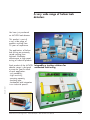
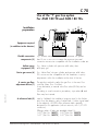
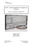
A very wide range of helium leak
detectors
You have just purchased
an ALCATEL leak detector.
This product is part of
a very wide range of
products resulting from
30 years of experience.
The applications of helium
leak testing are extremely
varied ranging from
high-tech installation
maintenance to high-speed
testing of industrial products.
Integrable or turnkey solutions for
automated leak testing
Edition 04 - July 97
Each product of the ALCATEL
detector range is designed
to meet the specific needs
of each application:
- unit portability;
- high sensitivity;
- pumping capacity;
- pumping type;
- automation and integration
in an industrial process.
Alcatel Vacuum Technology France - ASM 180 TD/TD+ - ASM 181 TD+ User’s Manual
1/1
France
Alcatel Vacuum Technology - France
98, avenue de Brogny - BP 2069
74009 ANNECY Cedex
Tel : (33) 4 50 65 77 77
Fax : (33) 4 50 65 77 89
Germany
Alcatel HOCHVAKUUMTECHNIK GmbH
Am Kreuzeck 10
D - 97877 WERTHEIM
Tel : (49) 9342 9610-0
Fax : (49) 9342 9610-30
Italy
Alcatel Vacuum Systems S.p.A
Via Trento, 30
20059 VIMERCATE (MI)
Tel : (39) 39 686 3855
Fax : (39) 39 667 125
Japan
Alcatel ITS JAPAN
High Vacuum Technology Division
Ebisu MT Building 5 Floor
15-7, Higashi 3-Chome
Shibuya-ku, TOKYO 150-0011
Tel : (81) 3 5468 1621
Fax : (81) 3 5468 1603
Korea
Alcatel Vacuum Technology Korea
5th Floor, Sunghyun B/D
10-5, Karak-Dong, Songpa-ku
Seoul, SOUTH KOREA
Tel : (82) 2 409 6277
Fax : (82) 2 409 6279
United Kingdom
Alcatel Vacuum Technology (U.K.) Ltd.
10 Lancaster Court - Coronation Road
HIGH-WYCOMBE, HP 12 3TD
Tel : (44) 1 494 448 444
Fax : (44) 1 494 448 222
USA
Alcatel Vacuum Products
67 Sharp Street
HINGHAM, MA. 02043
Tel : (1) 781 331 - 4200
Fax : (1) 781 331 - 4230
High Vacuum Technology
Alcatel Vacuum Technology - France - 98, avenue de Brogny - B.P. 2069 - 74009 ANNECY Cedex - France
Tel : (33) (0) 4 50 65 77 77, Fax : (33) (0) 4 50 65 77 89, Telex : 385 153 F
Contents
User’s Manual
ASM 180 TD/TD+ - ASM 181 TD+
Introduction
Edition 04 - September 97
Installation
MANUAL
REFERENCE
■ The ASM 180 series. . . . . . . . . . . . . . . . . . . ■ A
■ ASM 180 TD Detector operating principle . . . . ■ A
■ ASM 180 TD+ - ASM 181 TD+
Detector operating principle . . . . . . . . . . . . . . ■ A
■ Analyzer cell operating principle . . . . . . . . . . . ■ A
■ Testing methods . . . . . . . . . . . . . . . . . . . . . . ■ A
■ Operator interface . . . . . . . . . . . . . . . . . . . . ■ A
■ Options . . . . . . . . . . . . . . . . . . . . . . . . . . . ■ A
■ Accessories . . . . . . . . . . . . . . . . . . . . . . . . . ■ A
■ Technical characteristics . . . . . . . . . . . . . . . . . ■ A
■ Dimensions . . . . . . . . . . . . . . . . . . . . . . . . . ■ A
10
■ Precautions and unpacking. . . . . . . . . . . . . . . ■ B
■ Controlling the detector with the I/O interface . . . ■ B
■ Controlling the detector with
a micro-computer (RS232) . . . . . . . . . . . . . . . . ■ B
■ Connecting an external printer . . . . . . . . . . . . ■ B
■ Connecting a neutral gas purge (ASM 180TD only) ■ B
■ Connecting the leak detector to the installation
via the hardware interface . . . . . . . . . . . . . . . ■ B
■ Before starting up the detector . . . . . . . . . . . . ■ B
10
20
21
30
40
50
60
70
80
90
20
30
40
50
60
70
: 104435
EDITION : 04 - September 97
Alcatel Vacuum Technology France - ASM 180 TD/TD+ - ASM 181 TD+ User’s Manual
1/3
Contents
User’s Manual
ASM 180 TD/TD+ - ASM 181 TD+
Operation
■
■
■
■
■
Starting up the detector . . . . . . . . . . . . . . . . . ■ C 10
Detector operation . . . . . . . . . . . . . . . . . . . . ■ C 20
Detector autocalibration . . . . . . . . . . . . . . . . . ■ C 30
Switching off the detector . . . . . . . . . . . . . . . ■ C 40
Alphanumeric Control and Display Panel (ACDP)
operation. . . . . . . . . . . . . . . . . . . . . . . . . . . ■ C 50
■ Configuring the unit according to the gas to be
detected . . . . . . . . . . . . . . . . . . . . . . . . . . . ■ C 60
■ Use of the “I“ gas line option
ASM 180 TD/TD+ only . . . . . . . . . . . . . . . . ■ C 70
Troubleshooting
MANUAL
REFERENCE
■
■
■
■
■
■
■
■
■
■
■
■
Table of preventive maintenance intervals . . . . . ■ D 10
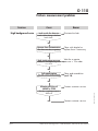
General troubleshooting guide . . . . . . . . . . . . ■ D 20
Problem with the roughing pump. . . . . . . . . . . ■ D 30
No display . . . . . . . . . . . . . . . . . . . . . . . . . ■ D 40
Problem with the secondary pump. . . . . . . . . . ■ D 50
Spectro fault . . . . . . . . . . . . . . . . . . . . . . . . ■ D 60
Inlet pressure problem . . . . . . . . . . . . . . . . . . ■ D 70
Cycle start faults . . . . . . . . . . . . . . . . . . . . . . ■ D 80
Faults at end of autocalibration. . . . . . . . . . . . ■ D 90
Faults in sniffer mode . . . . . . . . . . . . . . . . . . ■ D 100
Helium measurement problem . . . . . . . . . . . . . ■ D 110
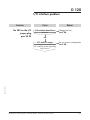
I/O interface problem. . . . . . . . . . . . . . . . . . ■ D 120
: 104435
EDITION : 04 - September 97
2/3
Alcatel Vacuum Technology France - ASM 180 TD/TD+ - ASM 181 TD+ User’s Manual
Edition 04 - September 97
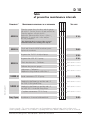
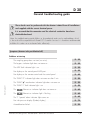
Maintenance
Contents
User’s Manual
ASM 180 TD/TD+ - ASM 181 TD+
Maintenance
Sheets
■
■
■
■
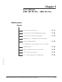
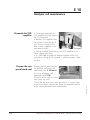
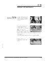
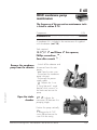
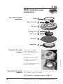
Analyzer cell maintenance . . . . . . . . . . . . . . . ■ E 10
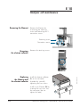
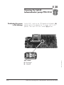
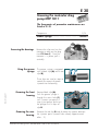
Greasing the hybrid turbomolecular pump . . . . ■ E 20
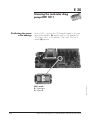
Greasing the molecular drag pump . . . . . . . . . ■ E 30
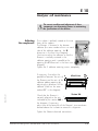
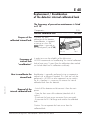
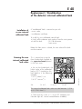
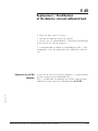
Replacement / Recalibration of the detector
internal calibrated leak . . . . . . . . . . . . . . . . . ■ E 40
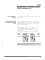
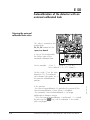
■ Autocalibration of the detector with an external
calibrated leak . . . . . . . . . . . . . . . . . . . . . . . ■ E 50
■ MD4E membrane pump maintenance . . . . . . . ■ E 60
■ CP20 Partial maintenance . . . . . . . . . . . . . . . ■ E 70
■ I/O interface board fuse replacement . . . . . . . ■ E 80
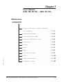
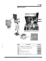
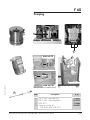
Components
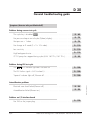
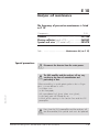
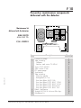
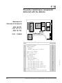
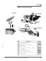
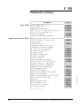
■ Preventive maintenance components delivered
with the detector. . . . . . . . . . . . . . . . . . . . . . ■ F 10
Edition 04 - September 97
■
■
■
■
■
■
■
■
■
■
■
Appendix
MANUAL
REFERENCE
: 104435
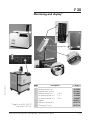
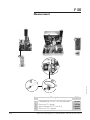
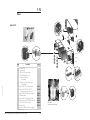
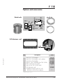
Monitoring and display . . . . . . . . . . . . . . . . . ■ F 20
Power and electrical supply . . . . . . . . . . . . . . ■ F 30
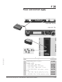
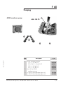
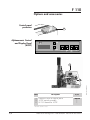
Automatism and electronic circuits . . . . . . . . . . ■ F 40
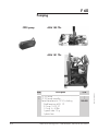
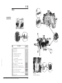
Measurement . . . . . . . . . . . . . . . . . . . . . . . . ■ F 50
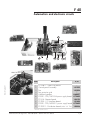
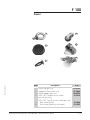
Pumping . . . . . . . . . . . . . . . . . . . . . . . . . . . ■ F 60
Valves . . . . . . . . . . . . . . . . . . . . . . . . . . . . . ■ F 70
Pipes . . . . . . . . . . . . . . . . . . . . . . . . . . . . . ■ F 80
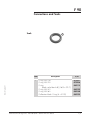
Connections and seals . . . . . . . . . . . . . . . . . ■ F 90
Cover . . . . . . . . . . . . . . . . . . . . . . . . . . . . . ■ F 100
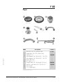
Options and accessories . . . . . . . . . . . . . . . . ■ F 110
Components summary . . . . . . . . . . . . . . . . . . ■ F 120
■ View of the operator interface . . . . . . . . . . . . ■ G 10
■ Recording curve . . . . . . . . . . . . . . . . . . . . . . ■ G 20
EDITION : 04 - September 97
Alcatel Vacuum Technology France - ASM 180 TD/TD+ - ASM 181 TD+ User’s Manual
3/3
Chapter A
User’s Manual
ASM 180 TD/TD+ - ASM 181 TD+
Introduction
■ The ASM 180 series . . . . . . . . . . . . . . . . . . . . ■ A 10
■ ASM 180 TD Detector operating principle . . . . . ■ A 20
■ ASM 180 TD+ - ASM 181 TD+
Detector operating principle . . . . . . . . . . . . . . . ■ A 21
■ Analyzer cell operating principle . . . . . . . . . . . . ■ A 30
■ Testing methods . . . . . . . . . . . . . . . . . . . . . . . ■ A 40
■ Operator interface. . . . . . . . . . . . . . . . . . . . . . ■ A 50
■ Options . . . . . . . . . . . . . . . . . . . . . . . . . . . . . ■ A 60
■ Accessories . . . . . . . . . . . . . . . . . . . . . . . . . . ■ A 70
■ Technical characteristics . . . . . . . . . . . . . . . . . . ■ A 80
Edition 04 - September 97
■ Dimensions. . . . . . . . . . . . . . . . . . . . . . . . . . . ■ A 90
Alcatel Vacuum Technology France - ASM 180 TD/TD+ - ASM 181 TD+ User’s Manual
1/1
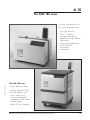
A 10
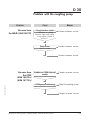
The ASM 180 series
The main characteristics of
this series of products are :
Edition 04 - September 97
- very high sensitivity
(2x10-11 mbar.l/s) ;
- a range of pumping
capacities to meet different
requirements ;
- sturdy design adapted to
severe industrial
environments ;
- user-friendly.
The ASM 180 series
includes different models :
- compact detectors (180) ;
- console detectors with
work surface (181) ;
- conventional detectors
equipped with oil sealed
vacuum pumps ;
- oil-free ("D") dry detectors.
Alcatel Vacuum Technology France - ASM 180 TD/TD+ - ASM 181 TD+ User’s Manual
1/2
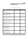
A 10
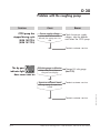
The ASM 180 series
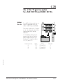
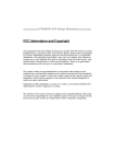
The versions according the detector types:
PUMPING
Standard:
1 Rotary vane pump PPM 2021
1 Hybrid pump PTM 5154
COMPACT VERSION
CONSOLE VERSION
ASM 180 T
ASM 181 T
Enhanced conventionnal roughing:
2 Rotary vane pumps PPM 2021
1 Hybrid pump PTM 5154
ASM 181 T
with 40 m3/h
roughing option
2 Rotary vane pumps PPM 2021
1 Turbomolecular pump ATP 100
1 Hybrid pump PTM 5154
ASM 181 T2
Dry +:
1 Dry pump Type CP20
1 Molecular drag pump MDP 5011
1 Hybrid pump PTM 5154
Enhanced dry roughing:
2 Dry pump Type CP20
1 Molecular drag pump MDP 5011
1 Hybrid pump PTM 5154
1
1
1
1
Dry pump Type CP20
Molecular drag pump MDP 5011
Turbomolecular pump ATP 100
Hybrid pump PTM 5154
2/2
ASM 180 TD
ASM 180 TD+
ASM 181 TD+
ASM 181 TD+
with 50 m3/h
roughing option
ASM 181 T2 D+
Alcatel Vacuum Technology France - ASM 180 TD/TD+ - ASM 181 TD+ User’s Manual
Edition 04 - September 97
Dry:
1 Primary membrane pump Type MD4E
1 Molecular drag pump MDP 5011
1 Hybrid pump PTM 5154
A 20
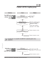
ASM 180 TD
Detector operating principle
Vacuum circuit
1
2
13
14
18
a
5
b
4
c
9
17
8
3
19
7
10
16
15
Edition 03 - May 97
1.
2.
3.
4.
5.
7.
8.
9.
10.
11.
Pumping capacities
Test capacities
Detector inlet port
Inlet vent valve
Vent filter connector
Roughing valve
Inlet pressure gauge (PI3C)
By-pass valve
Exhaust pressure gauge (PI1)
Exhaust valve
Roughing pump vent valve
Roughing membrane pump
(MD4E)
12
11
12. Roughing molecular drag pump
(MDP)
13. Detection valve
14. Calibrated leak module
15. Connector for long distance
sniffer
16. Sniffer valve
17. Hybrid turbomolecular pump
(PTM 5154)
18. Analyzer cell
19. Connector for inert gas purge
4 m3/h roughing (membrane pump MD4E)
+ 10 l/s ( molecular drag pump MDP).
Helium pumping speed at inlet port : 4.4 l/s.
Short test cycle.
Quick response time.
Autocalibration with integrated calibrated leak.
Alcatel Vacuum Technology France - ASM 180 TD/TD+ - ASM 181 TD+ User’s Manual
1/4
A 20
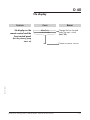
ASM 180 TD
Detector operating principle
Note: Only operational parts are represented.
Operation in
vacuum test mode:
3 stages
1a Primary roughing
1b Molecular roughing
1
1
5
5
4
4
7
12
11
12
11
Note: Valve 7 closes at about 6 mbar.
2 Gross leak test mode
(GL)
18
3 Fine leak test mode
(FL)
18
1
1
13
Edition 03 - May 97
5
4
17
17
9
9
12
2/4
11
12
11
Alcatel Vacuum Technology France - ASM 180 TD/TD+ - ASM 181 TD+ User’s Manual
A 20
ASM 180 TD
Detector operating principle
Operation in
sniffing mode (LDS)
18
Sniffer probe
15
16
17
9
11
Edition 03 - May 97
12
Alcatel Vacuum Technology France - ASM 180 TD/TD+ - ASM 181 TD+ User’s Manual
3/4
A 20
ASM 180 TD
Detector operating principle
Operation
in internal
calibration mode
1 Roughing of calibrated
leak
2 Calibration
14
18
14
a
c
17
9
12
11
12
11
3 Venting of calibrated
The leak is returned to
atmospheric pressure
14
4/4
b
Alcatel Vacuum Technology France - ASM 180 TD/TD+ - ASM 181 TD+ User’s Manual
Edition 03 - May 97
leak
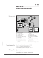
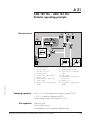
A 21
ASM 180 TD+ - ASM 181 TD+
Detector operating principle
Vacuum circuit
13
a
14
18
1
2
3
5
b
4
c
7
9
17
8
16
15
Edition 04 - September 97
1.
2.
3.
4.
5.
7.
8.
9.
12.
Pumping capacities
Test capacities
Detector inlet port
Inlet vent valve
Vent filter connector
Roughing valve
Inlet pressure gauge (PI3C)
By-pass valve
Exhaust pressure gauge (PI1)
Exhaust valve
Roughing molecular drag pump
(MDP)
12
20
13. Detection valve
14. Calibrated leak module
15. Connector for long distance
sniffer
16. Sniffer valve
17. Hybrid turbomolecular pump
(PTM 5154)
18. Analyzer cell
20. Dry primary roughing pump
(CP20)
25 m3/h (15 cfm) roughing (dry primary pump CP20)
+ 10 l/s ( molecular drag pump MDP).
Helium pumping speed at inlet port: 4.4 l/s.
Short test cycle.
Quick response time.
Autocalibration with integrated calibrated leak.
Alcatel Vacuum Technology France - ASM 180 TD/TD+ - ASM 181 TD+ User’s Manual
1/4
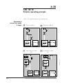
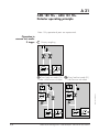
A 21
ASM 180 TD+ - ASM 181 TD+
Detector operating principle
Note: Only operational parts are represented.
Operation in
vacuum test mode:
3 stages
1 Primary roughing
1
5
7
4
12
20
2a Gross leak test mode (GL)
2b Gross leak test mode (FL)
1 mbar < Inlet Pressure < 6 mbar
18
1
1
5
5
4
4
7
17
17
9
9
12
2/4
6 mbar
Edition 04 - September 97
18
Inlet Pressure
20
12
20
Alcatel Vacuum Technology France - ASM 180 TD/TD+ - ASM 181 TD+ User’s Manual
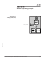
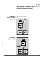
A 21
ASM 180 TD+ - ASM 181 TD+
Detector operating principle
Operation in
vacuum test mode:
3 stages
(continued)
3 Fine leak test mode (FL)
18
1
13
17
9
12
20
Edition 04 - September 97
Operation in
sniffing mode (LDS)
Sniffer probe
18
15
16
17
9
12
20
Alcatel Vacuum Technology France - ASM 180 TD/TD+ - ASM 181 TD+ User’s Manual
3/4
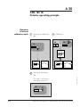
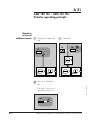
A 21
ASM 180 TD+ - ASM 181 TD+
Detector operating principle
Operation
in internal
calibration mode
1 Roughing of calibrated
leak
2 Calibration
14
18
14
a
c
17
9
12
20
12
20
3 Venting of calibrated
The leak is returned to
atmospheric pressure
14
4/4
b
Alcatel Vacuum Technology France - ASM 180 TD/TD+ - ASM 181 TD+ User’s Manual
Edition 04 - September 97
leak
A 30
Analyzer cell operating principle
Analyzer cell operating principle
4
He
Magnetic deflection
spectrometry
Leak flow rate
The mass spectrometry analyzer cell is used for helium
partial pressure measurements.
5
He
The molecules of the gas being analyzed are bombarded
by an electron beam from a heated tungsten filament (1) in
an ionization chamber (3).
A large proportion of the molecules are transformed into
ions. These ionized particles are accelerated by an electrical
field: the acceleration voltage. A magnetic field deflects the
ion beam by a radius propotional to the mass of the ions.
The acceleration voltage directs the Helium ions to the
target at the entrance of an amplifier, an electron multiplier
based system, developed and patented by ALCATEL.
6
N
magnetic
field
He
+ 200 V
adjustable
"
"
(Helium
peak)
Electron
multiplier
T arget
Acceleration
voltage
Cell principle
3
He leak signal
2
The stream of Helium ions is proportional to the partial
pressure of helium in the installation and its measurement is
used to find the value of the flow rate of the detected leak.
80 V
Electronic
current
0.2 - 2.0 mA
+
adjustable
(Sensitivity)
r
fie
pli
Am
Ie
Vacuum operation
Edition 03 - May 97
Separation of He ions
from "noise"
Total pressure
It is essential for the total pressure in the analyzer cell to be
less than 10-4 mbar so that the paths of the electrons and
ions are not disturbed by residual molecules.
1
1 Filament
2 Electron collector
In order to separate the helium ions from the "noise" due to
"dispersed ions", a "braking electrode" (6), placed in front
of the target, eliminates secondary, low-energy ions.
3 Ionization chamber
4 Triode electrode
5 Diaphragm
V
2.5
3A
The top of the cell contains an auxiliary electrode which
collects ions that have a higher mass than that of helium.
This electrode, the triode electrode (4), is used to measure
the total pressure inside the analyzer.
6 Braking electrode
Electron beam
"Heavy" ions
Alcatel Vacuum Technology France - ASM 180 TD/TD+ - ASM 181 TD+ User’s Manual
1/1
He
Helium ions
"Light" ions
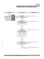
A 40
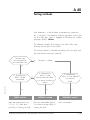
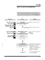
Testing methods
Leak detection is used to detect micro-openings, porosities,
etc. in test parts. The detection of these passages involves the
use of a light gas, which is capable of infiltrating the smallest
passages quickly: Helium.
The detector samples and measures the helium flow rate
entering the test part via the leak(s).
The testing method is selected according to the test part and
the measurement accuracy required:
The part can
be connected to
an evacuation line
no
The part is sealed
yes
Edition 03 - May 97
Its characteristics
allow it to be
evacuated
yes
SPRAY method
Leak rate measurement from
10-10 to 10-1 mbar and
possibility of locating the leak
no
Its characteristics
allow it to be
pressurised with helium
or a mixture containing
helium
yes
SNIFFING method
Minimum detectable leak of
10-6 mbar and possibility of
locating the leak
Alcatel Vacuum Technology France - ASM 180 TD/TD+ - ASM 181 TD+ User’s Manual
Its characteristics
allow it to be placed
in a vacuum
vessel
yes
BOMBING method
Leak not located
1/4
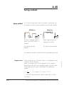
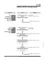
A 40
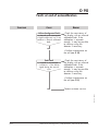
Testing methods
Spray method
This involves removing air from the test part, connecting it to
the analyzer and then spraying helium over the outer surface.
Spray test
Global test
Spray
Part
or
or
He
He
Part
Detector
Detector
The part is placed under a
cover, into which helium is
injected.
Areas liable to leak are
sprayed with helium.
The leak cannot be
located.
The leak can be located.
Response time
When spraying starts, the leak signal is not displayed instantaneously on the analyzer:
there is a response time which depends on the volume V
being tested and the helium pumping speed S of the system
at the opening of the part, according to the following
relation:
T =
V
S
(T in seconds, V in litres, S in l/s)
T is the time required for the signal to reach 63 % of the
final value.
2/4
Alcatel Vacuum Technology France - ASM 180 TD/TD+ - ASM 181 TD+ User’s Manual
Edition 03 - May 97
The detector measures the flow of helium penetrating the part.
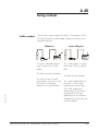
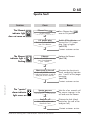
A 40
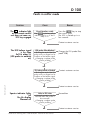
Testing methods
Sniffer method
The test part is pressurized with helium. The detector, via an
LDS (Long Distance Sniffer) probe, collects the helium escaping from the part.
Global test
Local sniffing test
or
He
Part
Detector
Sniffer probe
The part is placed under a
cover containing a sniffer
probe.
He
Part
Detector
Sniffer probe
The sniffer probe is moved
over areas likely to contain
leaks.
The leak cannot be located.
The leak can be located.
Edition 03 - May 97
The helium from the leak
accumulates over time inside
the cover. The detector
measures the concentration.
Alcatel Vacuum Technology France - ASM 180 TD/TD+ - ASM 181 TD+ User’s Manual
The signal supplied by the
analyzer is not a direct
measurement of the leak.
The sniffer probe only
collects part of the helium
escaping from the part
depending on the distance
separating the leak from the
tip of the probe.
3/4
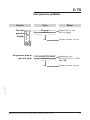
A 40
Testing methods
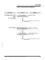
Bombing method
This method is used for sealed objects that cannot be
connected directly to the detector (semiconductors,
waterproof watches, etc.).
He
He
Part
Chamber 1
Part
Detector
Chamber 2
The part is placed in a vessel containing pressurised helium.
The helium penetrates the part if it has a leak.
This signal is not a direct measurement of the leak as the
helium pressure inside the part is difficult to determine. It
depends on the pressurisation time, pressurisation pressure,
internal volume of the part, dwell time before vacuum test
and size of the leak.
4/4
Alcatel Vacuum Technology France - ASM 180 TD/TD+ - ASM 181 TD+ User’s Manual
Edition 03 - May 97
The part is then removed from the vessel and placed in
another vacuum vessel which is connected to the detector.
The helium escapes from the part through the leak and
produces a signal.
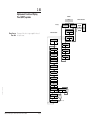
A 50
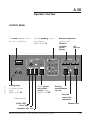
Operator interface
CONTROL PANEL
The counter operates when
the unit is switched on
Detector pumping system
status display.
(details on C 10)
AUDIO
00 00 00 0
Detection parameters
(analyzer cell)
electronic
ionization
current
display
TURBO
P
cell
pressure
SPECTRO
OK
0,2
1
-5
2
10
mA
MDP
AUTOCAL
-4
10
-3
10
mbar
Ie
1 V / dec
Edition 03 - May 97
OK
Analog output
to record the leak
signal
(details on C 20)
Alarm setpoint
and volume
control setting
(details on C 20)
Mode selection
Sniffer (LDS)
Gross leak
Automatic inlet vent
Alcatel Vacuum Technology France - ASM 180 TD/TD+ - ASM 181 TD+ User’s Manual
+
Detector
autocalibration
start-up
Emission
current fine
adjustment
Filament reset
1/2
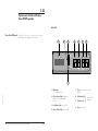
A 50
Operator interface
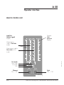
REMOTE CONTROL UNIT
Leak flow
(Helium signal)
display
Detector
inlet
pressure
display
Measurement
scale in Fine leak
mode
Measurement scale in
Gross leak or LDS
mode
Filament
ON / OFF
2/2
Edition 03 - May 97
Test mode
Gross leak
Fine leak
LDS
Cycle
ON / OFF
Alcatel Vacuum Technology France - ASM 180 TD/TD+ - ASM 181 TD+ User’s Manual
A 60
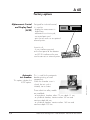
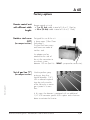
Factory options
Metal seals
These reduce the Helium background noise.
Metal seal locations
Inlet
port
Analyser
cell
Valve
block
Hybrid
turbomolecular
pump
Elastomer cell seal
Inlet
pressure
gauge
(PI 3C)
Used for easier maintenance operations on the analysis cell
(mass spectrometer).
This seal replaces the lead seal and can be reused.
Spare elastomer seal part number: 102823.
Edition 04 - September 97
In the event of a high helium concentration in the
room in which the test is being conducted, the
use of this type of seal may generate an increase
in the residual signal of the unit.
Control panel protection
3 masses
A Plexiglas cover equipped
with a key is used to lock
the access to the detector
setting parameters for nonqualified operators.
For use of one of the three following tracer gases:
Helium 4, Helium 3 or Hydrogen 2.
Alcatel Vacuum Technology France - ASM 180 TD/TD+ - ASM 181 TD+ User’s Manual
1/4
A 60
Factory options
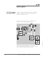
Designed for industrial control,
it is used to:
- display the measurement in
digital form,
- automate the unit test cycle,
- sort tested parts and
- print the test results on an optional
external printer.
It consists of:
- A user interface mounted
on the front panel of the detector
- an RS232 interface at the rear
used to connect an external printer.
Automatic
test chamber
This option includes the
ACDP option.
OK
He
F
C
OK
He
F
C
This is used for the automatic
bombing testing of small
components.
When the chamber cover is
closed, the test cycle is
initiated, via a contact.
Three aluminium alloy models
are available:
- a hemispheric chamber, diam. 72 mm, depth 31 mm;
- a cylindrical chamber, maximum diam. 85 mm and
maximum depth 68 mm;
- a cylindrical chamber, maximum diam. 160 mm and
maximum depth 200 mm.
2/4
Alcatel Vacuum Technology France - ASM 180 TD/TD+ - ASM 181 TD+ User’s Manual
Edition 04 - September 97
Alphanumeric Control
and Display Panel
(ACDP)
A 60
Factory options
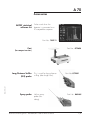
Remote control unit
with different cable
lenghts
Remote control unit with
- a 7 m (21 feet) cable instead of 3.5 m (11 feet) or,
- a 25 m (76 feet) cable instead of 3.5 m (11 feet).
Stainless steel cover
(UCT)
Designed for use of the unit
in clean rooms (“Ultra Clean
Technology“).
The front and rear covers
and frame are made of
stainless steel.
(for compact versions)
An adapter can be
attached to the side of
the unit for connection to
an exhaust system:
diameter 100 mm (Part No.: 102867 - proposed as accessories).
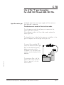
Test of gas line (“l“)
Edition 04 - September 97
(for compact versions)
Used to perform spray
testing on long lines
(typical diameter: 1/4“),
with a reduced response
time due to the transfer
of the helium by a carrier
gas injected in viscous
flow.
In this case, the detector is equipped with an additional
1/4“ VCR connector specific to this option and a luminous
button to activate the function.
Alcatel Vacuum Technology France - ASM 180 TD/TD+ - ASM 181 TD+ User’s Manual
3/4
A 60
Factory options
50 m3/h roughing
(for console version)
In order to reduce the roughing time when testing large
volumes, a second CP 20 rotary vane pump can be
added to the roughing system.
Vacuum circuit of the ASM 181 TD+ equipped with
the 50 m3/h (2x15cfm) roughing option :
13
a
14
18
1
2
3
5
b
4
c
7
9
17
8
16
12
20
20
Apart from the roughing capacity and the weight
(185 kg/406 lb with the option), the characteristics and
the use of the leak detector remain the same.
4/4
Alcatel Vacuum Technology France - ASM 180 TD/TD+ - ASM 181 TD+ User’s Manual
Edition 04 - September 97
15
A 70
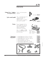
Accessories
ALSTAT statistical
software kit
To be used when the
detector is connected to a
PC-compatible computer.
Part No.: 785911
Cart
Part No.: 072654
(for compact versions)
Edition 03 - May 97
Long Distance Sniffer
(LDS) probe
Spray probe
This is used for long distance
sniffing (tube length=5m).
Helium spray
probe (less
tubing).
Alcatel Vacuum Technology France - ASM 180 TD/TD+ - ASM 181 TD+ User’s Manual
Part No: 072301
Part No.: 083465
1/2
A 70
Accessories
Exhaust line / adapter
(for compact versions)
Stainless steel cover option
required.
Part No.: 102867
Printer
This is connected to the I/O
interface and frees the
operator's hands.
The test cycle is initiated by
pressing on the pedal.
The unit equipped with the
ACDP option can issue test
tickets and autocalibration
reports to guarantee
measurement traceability.
Refer to the B 40 and C 50
section concerning the use of
the ACDP option.
Connection
components
Part No.: 100913
St.
St.
St.
St.
St.
St.
St.
steel
steel
steel
steel
steel
steel
steel
Part No.:
120V - 60Hz :
103593
100V - 50/60Hz :103594
220V - 50Hz :
102873
flexible hose L 250 mm - DN 40
flexible hose L 500 mm - DN 40
flexible hose L 1000 mm - DN 40
symmetrical T - DN 40
symmetrical cross - DN 40
reducing nipple DN40 / DN25
centering ring with viton seal DN 40
Part No.
068373
068374
068375
068564
068571
068253
068230
For any other accessories, contact our sales department.
2/2
Alcatel Vacuum Technology France - ASM 180 TD/TD+ - ASM 181 TD+ User’s Manual
Edition 03 - May 97
Cycle control pedal
A 80
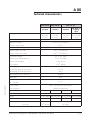
Technical characteristics
Roughing (primary) pump
ASM 180 TD
ASM 180 TD+
Standard
Standard
Standard
with 50 m3/h
roughing
option
4 m3/h
(2.4 cfm)
+ 10 l/s
25 m3/h
(15 cfm)
+ 10 l/s
25 m3/h
(15 cfm)
+ 10 l/s
2 x 25 m3/h
(2 x 15 cfm)
+ 10 l/s
Hybrid turbomolecular pump (air)
130 l/s
2.10-11 to 10-1 mbar.l/s
Measurement range
Electronic response time
< 0.1 s
8 decade log recording output
1 V/dec.
Setpoint setting - Fine leak
10-11 to 10-2 mbar.l/s
Setpoint setting - Gross leak
10-8 to 10-1 mbar.l/s
Inlet pressure display
103 to 10-3 mbar
Triode pressure display (Spectro)
10-5 to 10-3 mbar
Emission current display
0.2 to 2 mA
3.10-4 A/mbar
Cell sensitivity
He pumping speed at detector inlet port
4.4 l/s
Air pumping speed at spectrometer
110 l/s
He pumping speed at spectrometer
30 l/s
TMP exhaust pressure safety limit
6 mbar
Start-up time
3 min
Cycle time, inlet port blanked off
2-4s
(GL - FL mode)
Edition 04 - September 97
ASM 181 TD+
Power voltage
100, 115, 200, 220, 230, 240 V
Power frequency
50/60 Hz single-phase
Power consumption
1.2 kVA
1.5 kVA
Ambient operating temperature
Weight
2.4 kVA
10 to 40 °C
73 kg (160lb) 96 kg (210lb) 155 kg (340lb) 185 kg (406lb)
Noise level (at 1m; alarm not operational)
Inert gas purge:
1.6 kVA
54 dB
65 dB
65 dB
absolute pressure
1.4±0.1 bar abs.
No Purge
flow rate
1.10-2 mbar.l/s
No Purge
Alcatel Vacuum Technology France - ASM 180 TD/TD+ - ASM 181 TD+ User’s Manual
67 dB
1/1
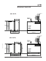
A 90
Dimensions (mm/inch)
ASM 180 TD
Inlet port
DN 40
220/8.7
450/
17.7 430/
16.9
96
/3.8
40/1.6
96
/3.8
40/1.6
210/
8.3
ASM
180 td
410/16.1
425/16.7
600/23.6
ASM 180 TD+
Inlet port
DN 40
Edition 04 - September 97
260/10.2
455/
17.9
450
430
/17.7
/16.9
210
/8.3
ASM
180 td+
455/17.9
465/18.3
Alcatel Vacuum Technology France - ASM 180 TD/TD+ - ASM 181 TD+ User’s Manual
600/23.6
1/2
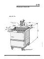
A 90
Dimensions (mm/inch)
ASM 181 TD+
200
7.9
l = 3.5m (11 feet)
(standard lenght)
Inlet port
DN 40
680
26.8
155
6.1
50 / 2.0
300
11.8
600
23.6
30
1.2
100
3.9
50/ 2.0
885
34.8
Edition 04 - September 97
170
6.7
80mm diam. casters
(without brakes)
2/2
Alcatel Vacuum Technology France - ASM 180 TD/TD+ - ASM 181 TD+ User’s Manual
Chapter B
User’s Manual
ASM 180 TD/TD+ - ASM 181 TD+
Installation
■ Precautions and unpacking . . . . . . . . . . . . . . . . ■ B 10
■ Controlling the detector with the I/O interface . . . . ■ B 20
■ Controlling the detector with
a micro-computer (RS232) . . . . . . . . . . . . . . . . . ■ B 30
■ Connecting an external printer . . . . . . . . . . . . . ■ B 40
■ Connecting a neutral gas purge
(ASM 180TD only) .
■ B 50
■ Connecting the leak detector to the installation
via the hardware interface . . . . . . . . . . . . . . . . ■ B 60
Edition 04 - September 97
■ Before starting up the detector . . . . . . . . . . . . . ■ B 70
Alcatel Vacuum Technology France - ASM 180 TD/TD+ - ASM 181 TD+ User’s Manual
1/1
B 10
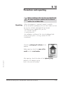
Precautions and unpacking
Before switching on the unit, the user should read
the safety instructions supplied with the detector
and be sure to follow them.
Unpacking
When the equipment is received, unpack it carefully:
do not discard the packaging until you have made sure that
the unit has not been damaged during transport.
The following are supplied with your unit:
- an instruction manual
- a maintenance kit
- the calibration certificate of the internal calibrated leak.
(If one of these parts is missing, contact ALCATEL
immediately).
Check the packaging tilt indicator of the
detector.
Edition 04 - September 97
Before opening, check the name of the
model and the serial number.
After opening, check the colour of the hydrating bags
packed in the detector casing.
(red in the event of humidity)
Alcatel Vacuum Technology France - ASM 180 TD/TD+ - ASM 181 TD+ User’s Manual
1/3
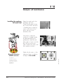
B 10
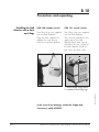
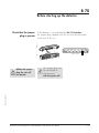
Precautions and unpacking
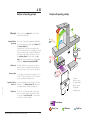
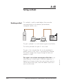
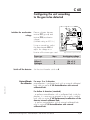
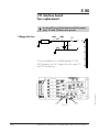
Handling the leak
detector with a hoist
and slings
ASM 180 compact version
ASM 181 console version
Two lifting rings are supplied
with the leak detector.
Plugs are also supplied to
replace the rings during
normal use of leak detector.
Four lifting rings are supplied
with the leak detector.
They must be located on the
upper part of the leak
detector frame after having
removed the work surface of
the leak detector (fixed by
one screw on each side).
2
2
1
2
2
1
In the event of any damage, contact the shipper and,
if necessary, notify ALCATEL.
2/3
Alcatel Vacuum Technology France - ASM 180 TD/TD+ - ASM 181 TD+ User’s Manual
Edition 04 - September 97
1 - Work surface fixing screws
2 - Location of the lifting rings
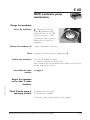
B 10
Precautions and unpacking
Storage
For prolonged storage, factors such as temperature, humidity,
saline atmosphere, etc. may damage the detector elements.
In this case, it may have operating problems.
Before starting up after storage for over six months, it is
recommended to change all the seals (contact customer
service).
The seal kits must be kept away from heat and light (direct
sunlight and ultraviolet light) in order to prevent hardening of
the elastomers.
Installation
The performances of the detector (pumping speed, accuracy
and reliability) depend on:
- the ambient temperature;
- the vacuum connections;
- the frequency and quality of maintenance;
- the helium calibration.
Edition 04 - September 97
Position the unit so there is no possible risk of the unit falling
or tilting.
Alcatel Vacuum Technology France - ASM 180 TD/TD+ - ASM 181 TD+ User’s Manual
3/3
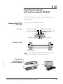
B 20
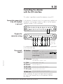
Controlling the detector
with the I/O interface
This makes it possible to control the detector using a PLC.
Connect the jumper plug
if the I/O interface
is not used
In the absence of external control, the jumper plug supplied with
the detector must be kept in place in order to use the operator
interface (contacts 23-24 connected):
1
0V
14
Prepare the
connector wiring
23 24
13
1
23
8
20
18
17
16
14 15
22
0V 24VDC
21 22 23 24 25
The common
points of the
controls are
pins 21 and
24.
It is recommended to use a shielded cable which is grounded
on the connector cap.
The controls
(inputs)
23 Interface
Contact open:
the detector is controlled by the I/O interface,
the operator can not access the keys
on the control panel or the filament key
on the remote control unit.
Contact closed:
the unit is controlled by the operator interface.
Edition 03 - May 97
22 Calibration Falling edge:
Autocalibration sequence start
8
Cycle
Falling edge: Cycle start
20 Filament
Closed: Filament on
18 GL mode
Closed: Gross Leak mode selection
17 LDS mode Closed: LDS mode selection
16 Inlet vent
Closed: Automatic vent mode selection
Note: if contacts 22 and 8 are kept closed to ground,
the "cycle" and "autocal" keys on the operator interface
are inactive.
Alcatel Vacuum Technology France - ASM 180 TD/TD+ - ASM 181 TD+ User’s Manual
1/2
B 20
Controlling the detector
with the I/O interface
The signals Contact closed
(outputs)
1 - 2
Sniffer mode (LDS)
Dry contacts:
Direct current:
60V - 60W or 2A max
Alternative current:
40V - 125VA or 2A max
Recorder output
-
4
6
9
11
13
15
15
15
24
21
Gross Leak mode
Fine Leak mode
Cycle in progress
Filament on
Helium signal > Reject setpoint
Analog output 0 - 10 VDC (inlet pressure)
0 - 8 VDC analogue output (Helium signal)
Internal ground
Common (external ground)
Common (external ground)
Edition 03 - May 97
Note:
3
5
7
10
12
19
14
2/2
Alcatel Vacuum Technology France - ASM 180 TD/TD+ - ASM 181 TD+ User’s Manual
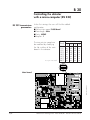
B 30
Controlling the detector
with a micro-computer (RS 232)
The RS232 interface is used to control the detector with a
micro-computer.
Preparing the RS 232
link cable
Pins used
Use a Sub D9 pin, female connector.
(Reception data) RD
TD (Transmission data)
(Data set ready) DSR
DTR (Data terminal ready)
GND (Ground)
1
2
6
(Ready to send) RTS
3
7
4
8
5
9
CTS (Clear to send)
Connection cable
6
9
1
1
5
5
Micro-computer
6
9
Detector
Edition 04 - September 97
(
7 and 8 Connections are necessary only if RTS and
LTS are used in a software created by the user)
Connecting
the detector to
a micro-computer
0
ASM 18
n
ct versio
Compa
n
le versio
1 Conso
ASM 18
Alcatel Vacuum Technology France - ASM 180 TD/TD+ - ASM 181 TD+ User’s Manual
1/8
C82
R232
C75
+
C61
+
+
+
+
C55
Y1
C49
C50
5V
250V
R229
C46
CR56
C40
C41
C42
C43
J8
+
+
Q13
C28
C29
C30
R160
CR40
CR41
R161
R162
Q29
R163
CR42
R164
CR45
+
+
-
C27
C23
R138
R139
R140
C24
R148
R147
R141
R142
C25
R144
R143
CR31
R145
CR32
CR33
CR34
R146
R147
R148
R149
R150
R151
R236
CR85
R238
R237
R152
CR35
R153
R154
R155
ST28
CR42
R156
TP5
C26
C16
C17
R110
R111
R112
R114
R115
R116
R117
R118
R119
R120
R121
R122
CR29
C18
R123
CR30
Q12
R124
Q11
R125
C19
R126
R127
C20
R128
R129
R130
R131
R132
R133
R134
R135
R136
R137
C2
C14
Q30
J50
R105
R106
R107
R108
R109
CR25
R95
R96
R97
R98
R99
C10
CR26
R100
R101
R102
C13
C12
J31
R104
CR27
CR28
+
+
C31
TP6
CR36
R165
Q15
R174
R245
R244
R243
R242
R241
R240
R167
R166
R168
CR46
CR47
R169
CR48
CR49
CR50
R170
R171
R172
CR51
CR39
R167
CR91
CR92
R239
C32
C33
C35
R175
CR88
TP7
+
C44
R178
R179
R180
R181
C39
C36
C107
-
+
C34 +
+
J30
TP16
+
CR57
C47
R182
R183
C37
C114
S1
Edition 04 - September 97
C84
C98
C54
Q18
R68
R69
C109
+
CR84
C105
J28
Q7
R56
R57
R58
R59
R60
CR14
CR15
R61
R62
CR16
R63
R64
C7
C8
R65
R66
R67
R68
R69
R70
R72
R71
CR17
R235
R74
R75
R76
CR18
CR19
R77
CR20
Q6
Q8
R78
R79
R80
R81
R82
R83
CR21
Q10
R88
R234
R84
R85
R86
R87
CR22
CR23
R89
R90
C9
R91
R92
R93
+
J37
R36
R37
R38
R40
A1
Q4
C5
R41
Q3
Q5
R42
R43
CR12
R44
R45
R46
R47
R48
R49
R50
R51
CR13
R52
R53
R54
C6
R2
R3
CR1
C1
R1
C3
R8
R7
R39
R5
R6
R4
Q2
C85
C86
C87
C88
R227
C97
R203
CR73
CR74
R209
25Z0V
C83
C81
C87
C52
C53
Q19
R198
R231
C45
ST26 TP15
C104
Q1
R22
R23
C2 +
CR4
CR5
R14
R15
R16
CR6
CR7
R17
CR8
R18
R19
R20
C4
CR9
CR10
R21
R10
CR2
R11
R12
R13
CR3
TP12
K4
K4
Z8
Z9
S4
S3
S2
J24
TP18
R9
A2
A3
C95
C96
AC
R221
R222
R223
R75
Q20
R199
R70
R71
R72
TP8
Z18
Z6
Z7
K5
Z11
Z12
CR37
CR83
R157
CR82
R158
CR38
TP13
C160
C158
Z15
ST3
ST23
Z20
CR86
J39
ST32
J3
R25
R26
R27
R28
R29
R30
R24
AC
ST4
ST5
ST6
R210
R76
R200
Q21
G22
R201
R202
J21
CR43
Z1
K1
A4
A5
Z2
TP19
TP17
TP14
CR24
TP3
K2
R55
ST25
J63
C126
Q24
Q25
R77
R78
R79
G23
J27
R94
ST33
Q9
C21
TP4
A6
C128
J61
K3
Z4
A7
J60
K6
A10
A11
R230
C11
R103
TP1
TP2
A8
Z5
ST23 ST22
A12
Z14
R211
R212
Q26
Q27
R213
R214
C73
Q28
J26
C74
+
C103
ST21
Z10
A13
R177
CR53
C110
+
CR55
C38
J4
R185
J62
Z21
Z22
Q17
Z17
C162
C163
C164
TP9
C49
ST10 ST9
Q31
K7
K8
K9
TP11
Q16
R246
TP10
C111
R228
CR65
J25
Y2
Z32
Y3
Z23
Z24
R197
R196
Z19
C112
C113
K6
R176
C106
C100
C165
J45
C108
CR54
PF1
Z27
C48
J42
J34
C51
R195
CR67
R190
CR62
R194
CR66
R189
CR61
Z28
Z25
ST12
R208
R207
R206
R205
R204
R193
CR65
R188
CR60
R192
CR64
R187
CR59
R191
CR63
R186
CR58
ST11
Z29
Z30
Z31
C101
R219
R218
R217
R216
R215
1
off
on
off
off
on
on
off
on
nu = pin not used
S6
ST24
Main board
4
nu
nu
nu
nu
nu
nu
nu
nu
Switch
2
3
off off
off off
on off
off on
off on
on off
on on
on on
Speed
(Baud)
110
150
300
1200
1800
2400
4800
9600
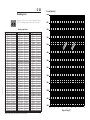
The transmission speed can
be modified by modifying
the S6 switches of the main
board in the detector.
R226
Z33
ST29
20
19
ST18
ST17
ST16
ST15
J41
ST30
ST31
R220
R32
R33
R34
R35
CR11
R31
J38
J40
Alcatel Vacuum Technology France - ASM 180 TD/TD+ - ASM 181 TD+ User’s Manual
2/8
At the first start-up, the user will find the default
configuration:
■ Transmission speed: 9600 baud
■ Data length: 8 bits
■ Parity: NONE
■ Stop bit: 1
RS 232 transmission
parameters
PO316E1
B 30
Controlling the detector
with a micro-computer (RS 232)
ON
S6
1 2 3 4
OFF
Board located inside the detector front cover
+
+
+
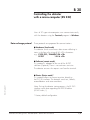
B 30
Controlling the detector
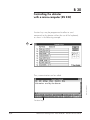
with a micro-computer (RS 232)
Users of PC type micro-computers can communicate easily
with the detector using the Terminal program in Windows.
Data exchange protocol
Three protocols are proposed for communications:
■ Hardware (local mode)
The detector sends a continuous data stream reflecting its
status in the form of a string of 50 <CR> characters.
e.g.: CYCLE OFF / FILAMENT ON <CR>
FL TEST
1.2 E-8 <CR>
■ Software (remote mode)
This protocol is adapted to the use of the ALSTAT
software (Optional). There is no continuous emission.
The detector answers the requests sent from the terminal.
Edition 04 - September 97
■ Printer (Printer mode)*
This protocol allows to connect a printer directly to
the RS 232 interface. The detector sends test-, default-,
autocalibration- and auto zero-tickets.
Note: During the detector start-up process, the RS 232
interface sends data regarding the EPROM edition
(L0040 index /).
* Factory default configuration.
Alcatel Vacuum Technology France - ASM 180 TD/TD+ - ASM 181 TD+ User’s Manual
3/8
B 30
Controlling the detector
with a micro-computer (RS 232)
Protocol selection
Common protocol
commands
The selection of the protocol is made from the microcomputer with following commands:
"L" Local
Hardware protocol
"R" Remote
Software protocol
"P" Printer
Printer protocol
Language selection
"F" French
"E" English
"D" German
ASCII Code 05
09
26
Commands
"A" Cell autocalibration start
"C" Test cycle start under vacuum
"B" LDS test cycle start
"S" Test cycle stop (vacuum or LDS)
«U» GL mode selection, same as key
«u» GL mode selection cancelled
«V» Air vent, same as key
«v» No air vent
«T» Manual adjustment of helium peak ON
«t» Manual adjustment of helium peak OFF
«Q» Manual adjustment of emission current ON
«q» Manual adjustment of emission current OFF
"ctrl E" Switches the filament on/off
"ctrl I" Returns to the factory default configuration values
of emission current and helium peak calibration
"ctrl Z" Returns to the default zero value (helium signal)
"+" Increase selected parameter
"-" Decrease selected parameter
=DA dd mm yy<CR> Adjustment of date
=TI hh mn ss<CR>
Adjustment of time
=STB xx<CR>
Timer for CP 20 stand-by mode
(reduced rotational speed): 01 to 60 min
(default value is 01 min)
4/8
Alcatel Vacuum Technology France - ASM 180 TD/TD+ - ASM 181 TD+ User’s Manual
Edition 04 - September 97
List the commands
"space"
B 30
Controlling the detector
with a micro-computer (RS 232)
Software (Remote) mode The detector sends back the requested data:
ASCII Code 06
"ctrl F"
The detector sends back its status in code form:
A<CR>
R<CR>
T 1.0E-7<CR>
TG 1.0E-7<CR>
Detector not in Cycle
Detector in roughing phase or
the filament is off
Detector in FL test mode, it sends
back the measured helium signal
Detector in GL test mode, it sends
back the measured helium signal
Printer mode The detector sends tickets:
Test ticket:
MANUAL CYCLE
C=Elapsed time (H.M:S)
S=Signal (mbar.1/s)
MANUAL CYCLE
C=Elapsed time (H.M:S)
S=Signal (mbar.1/s)
CYCLE START:
13 NOV. 1996
10.48:13
LDS START:
13 NOV. 1996
10.48:29
Residual helium signal
when cycle is started
C=00.00:00
S=4.4E-10
C=00.00:00
S=3.6E-10
Elapsed time for
GL crossover
GL MODE:
C=00.00:06
S=4.4E-10
STOP LDS:
C=00.00:13
S=2.3E-05
FL MODE:
C=00.00:07
S=7.8E-07
ALCATEL ASM180 series
LDS LEAK RATE: 1.5E-9
UNITS: mbar.1/s
13 NOV. 1996
10.48:42
Elapsed time for
FL crossover
Edition 04 - September 97
Sniffing test ticket:
Helium signal before
switching to FL mode
Cycle duration
Helium signal
at the end of the cycle
STOP CYCLE:
C=00.00:12
S=1.5E-09
ALCATEL ASM180 series
LEAK RATE: 1.5E-9
UNITS: mbar.1/s
13 NOV. 1996
10.48:25
Autozero ticket:
ALCATEL ASM180 series
ELECTRICAL ZERO O.K.
13 NOV. 1996
10.47:59
Alcatel Vacuum Technology France - ASM 180 TD/TD+ - ASM 181 TD+ User’s Manual
Autocalibration ticket:
ALCATEL ASM180 series
CALIBRATION COMPLETED
Calibrated leak value
7.7E-08 mbar.1/s
13 NOV. 1996
10.47:34
5/8
B 30
Controlling the detector
with a micro-computer (RS 232)
Printer mode
(continued)
Default ticket:
DEFAULT CODE: 200
13 NOV. 1996
10.49:06
List of defaults
*3 digit code = FAMILY code (1) + DEFAULT code (2)
**0** INIT DEFECTS**************************
* 011
* 012
* 013
*RAM test defect
*Real time clock defect
*EPROM Checksum defect
**1** RS232 COMMAND DEFECTS***************
*
*
*
*
100
101
102
103
*Time Out Expired
*Unknown command
*Uncomplete command line
*Invalid character
*
*
*
*
*
*
*
*
*
*
200
201
202
204
205
206
208
209
210
211
*Spectro parameter Unit
*Incompatible reference leak value
*Background level too high
*Helium Peak Adjustment defect
*Emission current adjustment limit exceeded
*Calibration Interupted
*Electronic Zero Init
*Filament emission defect
*Triode (spectro) pressure safety activated
*Amplifier Zero adjustment Init
**3** PUMPING SYSTEM DEFECTS****************
*
*
*
*
*
6/8
301
302
303
304
305
*Exhaust pressure > 10 mbar
*TMP in acceleration mode
*TMP defect
*LDS flow too high
*LDS probe clugged
Alcatel Vacuum Technology France - ASM 180 TD/TD+ - ASM 181 TD+ User’s Manual
Edition 04 - September 97
**2** SPECTRO DEFECTS**********************
B 30
Controlling the detector
with a micro-computer (RS 232)
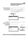
Example of
communication with a PC
Terminal operation under Window 3.11.
As soon as the connections are done and the Terminal
function opened under Window, the main two parameters
to be configured are Emulation and communication.
1
3
2
1
Edition 04 - September 97
2
Alcatel Vacuum Technology France - ASM 180 TD/TD+ - ASM 181 TD+ User’s Manual
7/8
B 30
Controlling the detector
with a micro-computer (RS 232)
Function keys may be programmed to allow to send
commands to the detector without the use of the keyboard,
as shown in the following example.
3
Then, communication can be settled.
Edition 04 - September 97
Information send by the detector
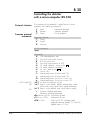
Function keys
8/8
Alcatel Vacuum Technology France - ASM 180 TD/TD+ - ASM 181 TD+ User’s Manual
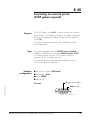
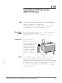
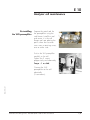
B 40
Connecting an external printer
(ACDP option required)
Purpose
Type
Interface
configuration
The ACDP option (see A 60) is used to connect an external
printer directly to the detector and print test tickets, calibration
tickets or test parameter readings stored inside the detector
(see C 50).
This type of function guarantees the traceability of leak
testing operations.
Any printer equipped with an RS232C type serial link is
suitable. It should have a minimum buffer memory of 2K.
The tickets printed using the ACDP option contain a
maximum of 25 characters per line.
The external printer should get electrical power from a
source external to the detector.
■
■
■
■
Transmission speed: 9600 baud
Data length: 8 bits
Parity: NONE
Stop bit: 1
TD (Transmission data)
Pin used:
Edition 04 - September 97
GND (Ground)
1
2
6
3
7
4
8
5
9
Detector male connector
Alcatel Vacuum Technology France - ASM 180 TD/TD+ - ASM 181 TD+ User’s Manual
1/4
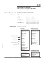
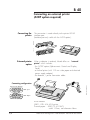
B 40
Connecting an external printer
(ACDP option required)
Connecting the
printer
The connection is made directly to the printer RS232
interface port.
(Interface port only valid with the ACDP option).
ersion
mpact v
0 Co
ASM 18
1
ASM 18
External printer
option
Console
version
When a detector is ordered, Alcatel offers an "external
printer" which includes:
- the "ACDP" option (Alphanumeric Control and Display
Panel),
- a thermal printer (with 112 mm wide paper and electrical
power supply adapter);
- the detector / printer connection cable.
Connecting configuration
5
20
Printer side
3
7
6
Edition 04 - September 97
Detector side (female)
SubD 9 pin
2
SubD 20 pin
(serial port)
Printer offered:
SEIKO - DPU 414 40 B printer
Thermal paper - SEIKO TP 411-28CL
width 112mm, reel diameter 48mm.
2/4
Alcatel Vacuum Technology France - ASM 180 TD/TD+ - ASM 181 TD+ User’s Manual
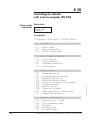
B 40
Connecting an external printer
(ACDP option required)
Connecting a PC
micro-computer to the
RS 232 printer interface
The connection of a PC micro-computer allows to customize
the reference of the parts to be tested under of the control of
the ACDP option (see C50).
Wiring and transmission are done in the same way as for
standard RS 232 link (see B30).
ersion
mpact v
0 Co
ASM 18
1
ASM 18
Console
version
(Reception data) RD
TD (Transmission data)
(Data set ready) DSR
DTR (Data terminal ready)
GND (Ground)
1
2
6
(Ready to send) RTS
7
4
8
5
9
CTS (Clear to send)
Sub D9 pin, female
Connecting cable
6
9
Edition 04 - September 97
3
1
1
5
5
Micro-computer
6
9
Detector
(
7 and 8 Connections are necessary only if RTS and
LTS are used in a software created by user)
Link configuration
Speed: . . . .
Data length:
Parity: . . . .
Stop bit: . . .
.
.
.
.
.
.
.
.
.
.
.
.
.
.
.
.
.
.
.
.
.
.
.
.
.
.
.
.
.
.
.
.
.
.
.
.
Alcatel Vacuum Technology France - ASM 180 TD/TD+ - ASM 181 TD+ User’s Manual
.
.
.
.
9600 bands
8 bits
None
1
3/4
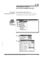
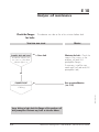
B 40
Connecting an external printer
(ACDP option required)
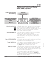
Example of customized
reference of the tested
part via ACDP option
(see procedure in C50)
• Connect the PC to RS 232 printer interface as explained
above.
• Set the Terminal function under Window (see B30).
• As soon as the ACDP panel proposes the choice of a part:
(Basic part modification menu see C50, page 17).
• Send from the PC "CTRL D" and then the 16 characters to
identify the part (see C50, page 18).
PART SELECTION ?
NUMBER : 1
FILE SELECTION ?
RELAI 22S ACD
(Copy of test ticket)
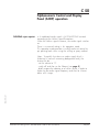
• PC connected to RS 232 printer interface : See on C50 for
the operating mode of ACDP option.
At the end of an automatic test
ACDP Display
panel
Detector
ACCEPTED 2.0E-10
READY/AUTO CYCLE
NEXT NUMBER :
RELAI 22S ACD
4/4
4
Alcatel Vacuum Technology France - ASM 180 TD/TD+ - ASM 181 TD+ User’s Manual
Edition 04 - September 97
Example of the
acquisition on a PC of a
test result controlled by
the ACDP option
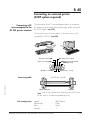
B 50
Connecting a neutral gas purge
(ASM 180 TD only)
Use
- Used to accelerate the cleanup of the helium background
noise after detecting a significant leak.
- Make high sensitivity testing easier due to the reduction
and stabilization of the helium background noise.
Neutral gas
supply
The neutral gas supplied must have a helium concentration
less than or equal to 1 ppm.
Supply pressure: 1.4 ± 0.1 bar (absolute) ( 20 psia).
Connection
Edition 03 - May 97
Note
A quick connector is
located to the left at the
rear of the detector near
the LDS connector. The
corresponding male
connector (to be fitted
on the gas inlet tube) is
supplied in a plastic
bag with the detector.
N2
The neutral gas purge connector is different than the inlet
hole connector. The latter can also be connected to a
neutral gas source to purge the inlet and anything connected
to it at the end of a cycle. The supply pressure of the gas
for the inlet vent must be atmospheric pressure 1,0 +0,2
+0 atm
absolute ( 14 psia).
Alcatel Vacuum Technology France - ASM 180 TD/TD+ - ASM 181 TD+ User’s Manual
1/1
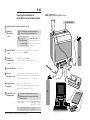
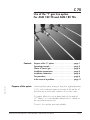
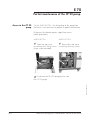
B 60
Connecting the leak detector to
the installation via the hardware interface
ASM 180 TD/TD+ compact versions
DN 40 INLET PORT
1 Connect the remote control unit (Sub D 25 pts plug)
2 Connect the
The I/O interface connector should never be
connected or disconnected with the unit on.
I/O interface
If the detector is not
controlled by
the I/O interface:
the jumper plug
must be connected.
(see B 20)
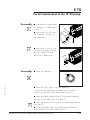
3 Connect the RS232
(see B 30)
4 Connect an
external printer
It the detector is controlled
by the I/O interface, install
the interface cable to the
Sub D 25 pin connector on
the detector.
1
If the detector is to be connected to a micro-computer,
connect the cabled RS232.
N2
(ACDP option required see A 60)
Connect the printer output using an RS232 cable.
(see B 40)
5 Connect the LDS probe
(quick connector)
6 Connect to
When a neutral gas is used, the filter is unscrewed and
replaced by the connection to the selected gas supply source.
+0,2
1/4" BSP connector - Pressure : 1.0 +0 atm absolute
atmospheric pressure
7 Connect the inert
Edition 04 - September 97
8
gas purge
(quick connector - ASM 180 TD only)
The helium concentration of neutral gas must be
Pressure: 1,4±0,1 bar absolute ( 20 psia).
5
Power consumption . . . . . . . . . . . ASM 180 TD 1.2 kVA
. . . . . . . . . . . . . . . . . ASM 180 TD+ 1.5 kVA
Fuse
Voltage 200-220-240 V .......3.15AT
Voltage 100-115 V..............6.30AT
Alcatel Vacuum Technology France - ASM 180 TD/TD+ - ASM 181 TD+ User’s Manual
4
3
1 ppm.
Check that the voltage marked on the unit
identification plate corresponds to that of the
electrical source.
the main power
2
7
N2
8 Connect the unit to
6
1/2
ALSTAT
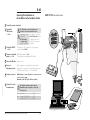
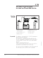
B 60
Connecting the leak detector to
the installation via the hardware interface
ASM 181 TD+ console version
1 Connect the remote control unit
The I/O interface connector should never be
connected or disconnected with the unit on.
2 Connect the
I/O interface
(see B 20)
If the detector is not
controlled by
the I/O interface:
the jumper plug
must be connected.
3 Connect the RS232
(see B 30)
If the detector is to be connected to a micro-computer,
connect the cabled RS232.
4 Connect an external
printer (see B 40)
(ACDP option required see A 60)
Connect the printer output using an RS232 cable.
5 Connect the LDS probe
(quick connector)
6 Connect to
When a neutral gas is used, the filter is unscrewed and
replaced by the connection to the selected gas supply source.
+0.2
1/4" BSP connector - Pressure : 1.0 +0 atm absolute
7 Connect accessories
Additional plugs : 3 power plugs allow to connect accessories
such as recorders, gauges,…
(Maximum current: 4A; Specific 4A Fuses provided).
atmospheric pressure
Edition 04 - September 97
8 Connect the unit to
socket
5
3
1
INLET PORT
1
2
N2
2
6
3
8
ALSTAT
Voltage 200-220-240 V .......3.15AT
Voltage 100-115 V..............6.30AT
Alcatel Vacuum Technology France - ASM 180 TD/TD+ - ASM 181 TD+ User’s Manual
plug
7
Power consumption ...........................1.6 kVA
Fuse
4
4
Check that the voltage marked on the unit
identification plate corresponds to that of the
electrical source.
the main power
plug
plug
It the detector is controlled
by the I/O interface, install
the interface cable to the
Sub D 25 pin connector on
the detector.
2/2
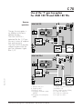
B 70
Before starting up the detector
Check that the jumper
plug is present
If the detector is not controlled by the I/O interface:
the jumper plug supplied with the unit must be connected
at the rear of the unit.
0
ASM 18
n
ct versio
Compa
1
0V
14
23 24
Jumper plug
The jumper plug must
be connected or
disconnected
with the power off.
Edition 04 - September 97
Without the jumper
plug, the unit will
not operate.
n
le versio
1 Conso
ASM 18
Alcatel Vacuum Technology France - ASM 180 TD/TD+ - ASM 181 TD+ User’s Manual
1/1
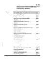
Chapter C
User’s Manual
ASM 180 TD/TD+ - ASM 181 TD+
Operation
■ Starting up the detector . . . . . . . . . . . . . . . . . . ■ C 10
■ Detector operation. . . . . . . . . . . . . . . . . . . . . . ■ C 20
■ Detector autocalibration . . . . . . . . . . . . . . . . . . ■ C 30
■ Switching off the detector. . . . . . . . . . . . . . . . . ■ C 40
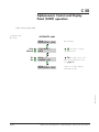
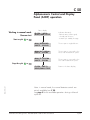
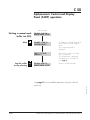
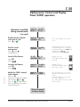
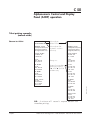
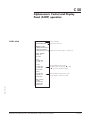
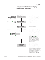
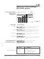
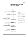
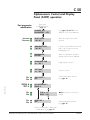
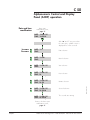
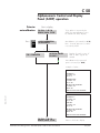
■ Alphanumeric Control and Display Panel (ACDP)
operation . . . . . . . . . . . . . . . . . . . . . . . . . . . . ■ C 50
■ Configuring the unit according to the gas to be
detected . . . . . . . . . . . . . . . . . . . . . . . . . . . . ■ C 60
■ Use of the “I“ gas line option
Edition 04 - September 97
ASM 180 TD/TD+ only. . . . . . . . . . . . . . . . . . ■ C 70
Alcatel Vacuum Technology France - ASM 180 TD/TD+ - ASM 181 TD+ User’s Manual
1/1
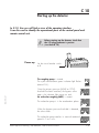
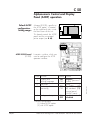
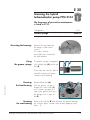
C 10
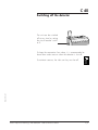
Starting up the detector
In G 10, the user will find a view of the operator interface.
It can be used to identify the operational parts of the control panel and
remote control unit.
Before starting up the detector, check that
the I/O plug connector is present
(see sheet B 70).
Power-up
Set the circuit breaker switch
to I
0
I
Edition 03 - May 97
The roughing pump is started.
The cycle control button green indicator light flashes.
(around 20s.)
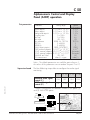
Once the primary pressure (MD4E or CP20)
threshold has been reached, the by-pass valve
opens, the indicator light comes on and
the molecular roughing (MDP) is started.
MDP
OK
MDP
The molecular pump is in the acceleration phase.
When the by-pass pressure threshold is detected,
the valve closes.
The molecular pump reaches its nominal rotational
speed in 2 to 3 min.
Alcatel - High Vacuum Technology - ASM 180 TD/TD+ - ASM 181 TD+ User’s Manual
OK
MDP
OK
MDP
OK
1/2
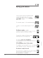
C 10
Starting up the detector
Once the exhaust pressure threshold has been
reached (after approximately 25 s), the P
indicator light comes on and the secondary
pump (TMP) is started.
TURBO
P
OK
TURBO
The secondary pump is in the acceleration phase.
P
OK
TURBO
It reaches its nominal rotational speed in 2 to 3
min.
P
OK
The filament on phase is started.
The filament key indicator light flashes for approx. 8 seconds
and becomes steady once the filament is emitting.
SPECTRO
0,2
1
2
-5
10
mA
The detector checks the cell calibration.
The autocalibration key red indicator light flashes for
a few seconds
(see autocalibration sheet C 30 for details).
If no problems are encountered, the unit is considered
to be calibrated: the green indicator light comes on.
-4
10
-3
10
mbar
AUTOCAL
AUTOCAL
The detector is ready to be used.
The cycle control is enabled when the green indicator
light on the cycle control key comes on.
(the autocalibration is validated)
2/2
Alcatel - High Vacuum Technology - ASM 180 TD/TD+ - ASM 181 TD+ User’s Manual
Edition 03 - May 97
The panel then displays the filament current
and the pressure in the analyzer cell.
C 20
Detector operation
In G 10, the user will find a view of the operator interface.
It can be used to identify the operational parts of the control panel and
remote control unit.
The following pages contain:
Working in vacuum test mode . . . . . . . . . . . Pages 1, 2
Working in Gross Leak mode . . . . . . . . . . . Page 2
Working in sniffer mode . . . . . . . . . . . . . . . Page 3
Setting the audio alarm setpoint . . . . . . . . . . Page 4
Saving the filament . . . . . . . . . . . . . . . . . . Page 5
Inlet port venting at the end of the test. . . . . . Page 5
Recording the Helium signal . . . . . . . . . . . . Page 5
Edition 04 - September 97
Working in
vacuum test mode
Make sure that the parts can withstand the
difference in internal/external pressure to which
they are subjected.
Connect the test part
P a rt
Alcatel - High Vacuum Technology - ASM 180 TD/TD+ - ASM 181 TD+ User’s Manual
1/5
C 20
Detector operation
Starting up evacuation of
the line and the part
Start a cycle by
pressing on the key
The pressure drop is shown on
the display unit.
According to the characteristics
of the test part and therefore
the pressure reached, the unit is
placed in gross leak or fine leak
test mode.
Gross Leak mode:
6 mbar > P > 2.10-2 mbar
Fine Leak mode:
P < 2.10-2 mbar
Working in Gross Leak
mode
It is possible to preset
the gross leak mode by
pressing the key
2/5
It is sometimes preferable
to work in Gross Leak
mode, in order to reduce
cycle times.
Alcatel - High Vacuum Technology - ASM 180 TD/TD+ - ASM 181 TD+ User’s Manual
Edition 04 - September 97
Note: The filament must be lit for a cycle to be started.
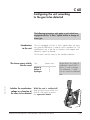
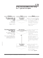
C 20
Detector operation
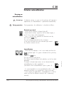
Working in Sniffer
mode (LDS)
Select the LDS
function.
ion
act vers
0 Comp
Connect the
probe to the quick
connector.
ASM 18
n
le versio
1 Conso
ASM 18
The filament emission goes off for a few seconds during the
probe roughing phase.
The test is operational
when the emission
presence indicator light
is lit.
The sniffer test mode indicator light
is lit on the unit.
The measured helium flow signal is
shown on the gross leak
measurement display.
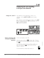
Edition 04 - September 97
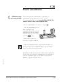
Check the probe operation When the LDS probe is placed in
the ambient air, the He signal
displayed is approximately
5.10-6 to 1.10-5 (equivalent to the
natural concentration of helium in
the air).
Check that the helium signal
decreases when the probe hole is
blocked with your finger.
Measured flow = concentration Given the detector configuration, the measured flow
corresponds to the helium concentration.
e.g.: Display of 5.10-6 corresponds to a measured leak of
5.10-6 mbar.l/s of He. and to a measured He concentration
of 5.10-6 or 5ppm.
LDS mode specificities The inlet pressure displayed on the remote control unit does
not affect operation (it is an independent circuit: see A 20).
The cycle key
is not used.
Alcatel - High Vacuum Technology - ASM 180 TD/TD+ - ASM 181 TD+ User’s Manual
3/5
C 20
Detector operation
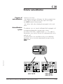
Audio alarm
(90 dB)
Display the alarm
setpoint by
pressing
Set the audio
alarm setpoint
The audio alarm is triggered when
the leak rate is greater than the
reject setpoint.
The frequency of the audio signal
depends on the leak rate
measured by the unit (the higher the rate,
the higher the signal frequency).
AUDIO
The threshold is then shown on the
measurement displays (Gross leak or
Fine leak depending on the test
mode used)
Adjust the setpoint using a
screwdriver to turn the
potentiometer.
Release the key.
Adjust the audio signal volume with the Audio section knob.
When this knob is at the minimum position (“0“ position),
the audio signal is cut off.
Edition 04 - September 97
Adjust the audio
volume
4/5
Alcatel - High Vacuum Technology - ASM 180 TD/TD+ - ASM 181 TD+ User’s Manual
C 20
Detector operation
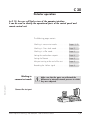
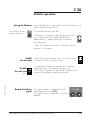
Saving the filament
Press the key on the
remote control unit.
To save the filament, it is possible to switch it off when it is not
to be used for a period of time.
The indicator light then goes off*.
The filament is switched on again by pressing on the
key a second time. The indicator light flashes for
approximately 8 s before lighting up, the filament is
now operating.
*Note: The filament can only be switched off when the
detector is in test mode.
Enable
the inlet vent
Disable
the inlet vent
Edition 04 - September 97
press
Record the helium
signal
When the inlet vent indicator light is lit, at the end of
the cycle, the inlet vent valve is open.
It is possible to disable the opening of this valve by
releasing the key. The indicator light goes out.
This function is important to prevent the installation from
returning to atmospheric pressure by mistake.
This output supplies a voltage of 0 to 8V.
(see recording curve in G 20)
The response curve is logarithmic (1 volt per
decade).
Alcatel - High Vacuum Technology - ASM 180 TD/TD+ - ASM 181 TD+ User’s Manual
1 V / dec
5/5
C 30
Detector autocalibration
Purpose of
autocalibration
Autocalibration
system
Used to ensure that:
- the detector analyzer cell detects the helium properly (test
of the Helium ion path so that they reach their target:
see A 30 Analyzer cell principle)
- the Helium leak value displayed corresponds to the real
value.
The detector uses an internal calibrated leak equipped with
a temperature-dependent compensation system.
The value of the leak is approximately 1 x 10⁻⁷ mbar.l/s.
Electrovalves are used to connect the calibrated leak to the
analyzer cell.
The electrovalves are controlled and the two calibration
parameters are set entirely automatically by pressing the
AUTOCAL
button.
a
14
Leak
b
c
Edition 03 - May 97
Autocal circuit layout
1
2
13
14
18
a
9
8
13
a
14
18
5
b
4
c
17
3
2
3
5
b
4
c
19
1
7
9
7
10
17
16
16
15
15
12
11
ASM 180 TD
Alcatel - High Vacuum Technology - ASM 180 TD/TD+ - ASM 181 TD+ User’s Manual
8
12
20
ASM 180 TD+
ASM 181 TD+
1/5
C 30
Detector autocalibration
Running an
autocalibration
1
2
At start-up
During operation
At detector start-up, as soon as the analyzer cell (spectro) is
operational, an autocalibration is performed automatically.
During operation, the calibration is checked as follows:
Autocalibration
- Check that the detector is not in test mode and that the
indicator light is lit; green indicator of the cycle key
lit.
- Press the AUTOCAL key
The red indicator light flashes;
The Helium signal oscillates and stabilizes on the fine leak
bargraph.
The green indicator light comes on to indicate that the
AUTOCAL
autocalibration has ben completed.
(see details of the autocalibration cycle in para. 4).
- It is recommended to run an autocalibration after 1 hour of
operation and then on a regular basis (once every day).
- In the majority of applications, autocalibration is used to
make sure that the detector analyzer cell is operating
correctly.
2/5
Alcatel - High Vacuum Technology - ASM 180 TD/TD+ - ASM 181 TD+ User’s Manual
Edition 03 - May 97
Electrical zero check
- Switch off the filament (indicator light off);
- check that the helium signal on the fine leak display is
at "0" (3 to 4 bars of the bargraph);
- if this is not the case, perform an electrical reset by
pressing the AUTOCAL key
The red indicator light flashes for a moment.
AUTOCAL
In the event of failure (the red indicator light remains
lit), contact customer service.
C 30
Detector autocalibration
3
Calibration range
Use of an external leak
If very accurate leak measurement is required in a
measurement range other than 1.10-8 - 1.10-6,
it is recommended to use an external calibrated leak, the
value of which is close to the required value:
- Run an autocalibration as shown in section 2
- Once the autocalibration has
been completed and
validated, connect the external
calibrated leak to the detector
inlet port and run a test cycle
with the
key,
- Wait a few minutes for
the Helium signal to stabilize,
Ie
+
- Adjust the displayed Helium signal value manually as a
function of the external calibrated leak using the filament
current fine adjustment potentiometer.
Edition 03 - May 97
Remember to take into account the effect of the temperature
on the value of the external calibrated leak in accordance
with the information given on the label. In the event of
problems, contact customer service.
Alcatel - High Vacuum Technology - ASM 180 TD/TD+ - ASM 181 TD+ User’s Manual
3/5
C 30
Detector autocalibration
4
Autocalibration
procedure
Throughout the autocalibration cycle, the "autocal" key red
indicator light flashes.
• Residual check.
• Autocalibration circuit roughing.
• Connection with the analyzer cell.
The Helium signal measurement is displayed.
• Comparison of the measured signal with the calibrated
leak value after waiting a few seconds for the signal to
stabilize.
If the difference is less than 10 %,
the autocalibration is stopped and validated.
If the difference is greater than 10 %,
the autocalibration is continued.
• Sensitivity adjustment.
The filament current in the analyzer
cell (see A 30) is automatically
adjusted so that the detector
displays a correct leak value
(internal calibrated leak value
corrected as a function of
temperature).
Stages 6 and 7 can be performed
several times if necessary, until the correct display is obtained.
4/5
Alcatel - High Vacuum Technology - ASM 180 TD/TD+ - ASM 181 TD+ User’s Manual
Edition 03 - May 97
• Helium peak detection. The
automatic control system varies the
acceleration voltage in the
analyzer cell (see A 30).
This varies the path of the Helium
ions until the maximum Helium
signal is obtained. The Helium
signal display oscillates during this
stage.
C 30
Detector autocalibration
• End of cycle.
The sequence has been performed correctly,
the detector is calibrated in Fine Leak mode,
the green indicator light comes on.
5
In the event of a
calibration fault
If a fault is encountered, the sequence is stopped and
the red indicator light comes on.
Faults which stop the autocalibration sequence are:
- zero impossible
- background signal too high
- sensitivity adjustment impossible
- voluntary stop by operator.
AUTOCAL
AUTOCAL
If the current cycle is stopped voluntarily, this is
considered as a fault.
Following a fault, the calibration parameters stored
previously are restored.
AUTOCAL
The "autocal" key red indicator light remains
continuously lit, a defect ticket is emitted on the
RS232 interface in printer mode (see B 30).
The "cycle" key green indicator light is lit.
The unit can still be used.
Edition 03 - May 97
After an initial autocalibration fault signal, it is recommended
to run a second autocalibration.
A repeated calibration fault is an indication that the cell is
"polluted" and requires maintenance.
Internal calibrated
leak service life
An internal calibrated leak can deliver helium for years. In
order to guarantee the reliability of measurements, in most
applications, ALCATEL recommends recalibration of the
internal calibrated leak at least every two years. The value
of the leak decreases over time according to a ratio
indicated on the internal calibrated leak label and on the
calibration certificate (e.g. 2 % every year).
The calibrated leak is recalibrated in approved centers,
using reference leaks : see E 40 for the internal calibrated
leak replacement procedure.
Alcatel - High Vacuum Technology - ASM 180 TD/TD+ - ASM 181 TD+ User’s Manual
5/5
C 40
Switching off the detector
The unit can be switched
off at any time by setting
the circuit breaker switch
to 0.
0
I
To keep the connection lines clean, it is recommended to
leave them under vacuum when the detector is shut off.
Edition 03 - May 97
To maintain vacuum, the inlet vent key must be off.
Alcatel - High Vacuum Technology - ASM 180 TD/TD+ - ASM 181 TD+ User’s Manual
1/1
C 50
Alphanumeric Control and Display
Panel (ACDP) operation
Contents
The present instructions only apply to units which are equipped
with the ACDP option.
Purpose of the ACDP option . . . . . . . . . . . . . . . . . . . . . . . page
Use of the configuration keys . . . . . . . . . . . . . . . . . . . . . . page
Start-up. . . . . . . . . . . . . . . . . . . . . . . . . . . . . . . . . . . . . . page
Access to the various configuration menus . . . . . . . . . . . . page
- Manual mode
- Automatic mode
}
2
3
4
5
Main menu
Working in manual mode - Vacuum test . . . . . . . . . . . . . . page 7
- Start a cycle
- Stop a cycle
Working in manual mode - LDS test . . . . . . . . . . . . . . . . . page 8
- Start a test
- Stop the test
Operations available during the manual test cycle . . . . . . page 9
-
Display the elapsed time
Print the current measurement
Switch off the filament
Switch on the filament
Example of test ticket in manual mode
Working in automatic mode (Vacuum test only) . . . . . . . . page 12
-
Start an auto test
Result messages at end of auto test
Error messages at end of auto test
Examples of auto test tickets
Edition 03 - May 97
Part modification menu . . . . . . . . . . . . . . . . . . . . . . . . . . page 15
-
Purpose of part modification menu
Automatic test parameters
Basic part modification menu
Test part selection change
Test part reference customization (via RS 232)
Automatic test parameter modification
Time and date modification
Unit autocalibration . . . . . . . . . . . . . . . . . . . . . . . . . . . . . page 21
Monitoring of the audio signal with the ACDP . . . . . . . . . page 22
Default unit configuration. . . . . . . . . . . . . . . . . . . . . . . . . page 24
- Internal switches
- Automatic test parameters - Setting ranges
Summary functional diagram (A3) . . . . . . . . . . . . . . . . . . page 26
View of ACDP panel (A3) . . . . . . . . . . . . . . . . . . . . . . . . . page 27
Alcatel Vacuum Technology France - ASM 180 TD/TD+ - ASM 181 TD+ User’s Manual
1/27
C 50
Alphanumeric Control and Display
Panel (ACDP) operation
Purpose of the ACDP
option
Manual operation
This option is intended for industrial inspection.
It is used to:
• display messages concerning the status of the detector;
• display the measurement in digital form;
• configure and control the unit in two operating modes
(manual or automatic);
• print inspection tickets using an external printer connected to
the associated interface (see B 40).
• To monitor the audio signal according to the selected
configuration
• The operator retains control of the test cycle start and stop
Automatic operation
• The test cycle is automated according to the programmable
test parameters.
• It is possible to program up to 10 references of different
parts each with its own test parameters.
• At the end of each automatic cycle, the test result is
displayed, the part is sorted as "Accepted" or "rejected"
according to the programmed reject level.
• An audio signal could be activated, according to the result of
the test and the selected configuration.
The ACDP panel operating instructions are given in the following pages.
We advise you to read them carefully in order to become familiar with its
operation.
At the end of C 50 (pages 26 and 27), the user will find a view of the front panel
of the option and a flow chart showing all the available functions.
2/27
Alcatel Vacuum Technology France - ASM 180 TD/TD+ - ASM 181 TD+ User’s Manual
Edition 03 - May 97
using the cycle key
or the C key on the ACDP.
• The Red and Green indicator lights (rejected part / accepted
part) come on according to the value of the Helium signal in
relation to the programmed manual reject level.
• The choice of test mode (gross leak, fine leak or sniffer) is up
to the user.
• The detector can be used as if it did not include this option
(see standard detector operation in C 20).
• The audio signal is working on a FIXED or FLOATING mode,
according to the selected configuration.
C 50
Alphanumeric Control and Display
Panel (ACDP) operation
Use of the
configuration keys
OK
He
F
▼ ▲
Edition 03 - May 97
C
F
C
This key is used to validate the selections made and to
access the various configuration menus.
It is activated in the basic display (see page 4).
These keys are used to select a response or adjust values.
They are activated whenever the display shows a "?".
To adjust values such as reject level, hold down
the ▼ or ▲ keys to scroll through the figures more
quickly.
This key allows to start a test cycle in manual or automatic
mode.
It also allows to stop the test cycle in manual mode.
It is activated when the display shows READY/AUTO CYCLE
or READY/MAN CYCLE.
Note: The cycle key of the remote control unit
has
priority over the control panel keys. This key remains
activated whatever the display. This note is valid for all
the commands of the standard detector (control panel and
remote control).
Alcatel Vacuum Technology France - ASM 180 TD/TD+ - ASM 181 TD+ User’s Manual
3/27
C 50
Alphanumeric Control and Display
Panel (ACDP) operation
Unit
start-up
(see also C 10)
START UP
XX min YY sec
The time is counted down until the
analyzer cell filament comes on.
AUTOCALIBRATION
IN PROGRESS
The control panel and remote
control unit keys are not functional
during this start-up phase.
CAL. COMPLETED
If MANUAL mode selected
FIL/ON : 1.0E-10
READY/MAN. CYCLE
Basic display
If AUTOMATIC mode selected
FILE # : 1
READY/AUTO CYCLE
Basic display
The basic display gives information which depends on the
operating mode (automatic or manual) in which the detector
was previously configured.
Using the basic display, the user can:
or C key);
• access the various configuration menus;
Pressing only the F key makes it possible to return to the
basic display without modifying any configuration
parameters.)
• perform an autocalibration.
See the following pages for further details.
4/27
Alcatel Vacuum Technology France - ASM 180 TD/TD+ - ASM 181 TD+ User’s Manual
Edition 03 - May 97
• start a test cycle (
C 50
Alphanumeric Control and Display
Panel (ACDP) operation
Access to the various
configuration menus
(Main menu)
Automatic mode
overleaf
MANUAL Mode
FIL/ON : 1.0E-10
READY/MAN CYCLE
Basic display
F
Auto ▲
Manual ▼
CYCLE MODE?
MANUAL
▲ ▼ are used to change
operating mode.
F
Yes ▲
No ▼
FILE # : 1
CHANGE ? NO
F
Floating ▲
Fixed ▼
MANU REJECT SETP
FIXED ?
F
Yes ▲
No ▼
▲ Yes : is used to access to
part modification basic menu
(see page 15)
The manual reject setpoint monitors :
- the switching of the Red light
indicator of ACDP panel (in relation
to the fixed reject setpoint only),
- the emission of an audio signal
(when controled by ADCP),
- The closing of the reject setpoint
contact on I/O interface (see B 20)
when the helium signal value is
greater than the setpoint (for further
details on Fixed/Floating,
see page 22).
Enable or disable the printer
interface in Manual mode.
PRINTER ?
NO
Edition 03 - May 97
F
ppm ▲
mbar.l/s ▼
LDS TEST UNITS ?
mbar.l/s
Selection of the measurement unit
in sniffer mode.
F
FIL/ON : 1.0E-10
READY/MAN. CYCLE
Alcatel Vacuum Technology France - ASM 180 TD/TD+ - ASM 181 TD+ User’s Manual
Return to the basic display
(Manual mode).
5/27
C 50
Alphanumeric Control and Display
Panel (ACDP) operation
Main menu (continued)
Manual mode
overleaf
AUTOMATIC mode
FILE # : 1
READY/AUTO. CYCLE
Basic display
F
Auto ▲
Manual ▼
CYCLE MODE ?
AUTO
▲ ▼ are used to change
operating mode
F
Yes ▲
No ▼
FILE # : 1
CHANGE ? NO
F
basic part modification menu
(see page 15)
Return to the basic display
(automatic mode).
Edition 03 - May 97
FILE # : 1
READY/AUTO. CYCLE
▲ Yes: is used to access the
6/27
Alcatel Vacuum Technology France - ASM 180 TD/TD+ - ASM 181 TD+ User’s Manual
C 50
Alphanumeric Control and Display
Panel (ACDP) operation
Working in manual mode
Vacuum test
Basic display
FIL/ON : 1.0E-10
READY/MAN. CYCLE
Indicates alternately:
- filament status, Helium signal,
- selected part reference,
- manual cycle standby message.
MAN./ROUGHING
INLET P. : 2.OE+02
The test part is roughed down.
MAN./GL : 5.OE-06
INLET P. : 5.OE-02
The test part is connected to the
Gross leak measurement system.
MAN./FL : 5.OE-08
INLET P. : 5.OE-03
The test part is connected to the
Fine leak measurement system.
FIL/ON : 5.0E-12
READY/MAN. CYCLE
Return to the basic display.
Start a cycle C or
Edition 03 - May 97
Stop the cycle C or
Note: in manual mode, the normal detector controls are
entirely available (see C 20).
See page 9 for the available operations during a Manual
cycle test.
Alcatel Vacuum Technology France - ASM 180 TD/TD+ - ASM 181 TD+ User’s Manual
7/27
C 50
Alphanumeric Control and Display
Panel (ACDP) operation
Basic display
Working in manual mode
Sniffer test (LDS)
Select
Stop the sniffer
test by releasing
FIL/ON : 1.0E-10
READY/MAN. CYCLE
FIL/DEF : 1.0 E-12
SPECTRO RESET !
The filament is off temporarily while
the LDS probe is being roughed
down.
The corresponding fault is
displayed.
LDS/T : 1.2 E-05
(mbar.l/s)
After a few seconds, the sniffer
test is operational.
The measurement is displayed
according to the selected unit
(see page 5).
FIL/ON : 5.0E-12
READY/MAN. CYCLE
Return to the basic display
Edition 03 - May 97
See page 9 for the available operations during a Manual
cycle test.
8/27
Alcatel Vacuum Technology France - ASM 180 TD/TD+ - ASM 181 TD+ User’s Manual
C 50
Alphanumeric Control and Display
Panel (ACDP) operation
Manual test basic display
Edition 03 - May 97
Operations available
during manual mode
test cycle
MAN./FL : 1.0 E-09
INLET P. : 1.0 E-03
Display the time elapsed
since start of cycle
Press ▼ or ▲
MAN./FL : 1.0 E-09
CHRONO : 27S
Print the current
measurement
Press ▼ and ▲
simultaneously
MAN./FL : 1.0 E-09
CHRONO : 37S
Switch off the filament
(see C20)
Press
FIL/DEF. : 1.0 E-12
SPECTRO RESET !
Vacuum test only.
The filament indicator light
goes off.
Switch on the filament
(see C20)
Press
MAN./FL : 1.0 E-09
INLET P. : 1.0 E-03
Vacuum test only
The filament indicator light is lit
after a few seconds.
Modify the FIXED manual
reject setpoint :
Press on F .
Adjust the displayed setpoint
with the key ▼ and ▲ .
Press on F to valid and to
return to display during the
manual cycle test.
MAN./FL : 1.0 E-09
REJECT ? : 1.0 E-08
Only if FIXED reject is selected
and when leak detector is in test
mode.
The FIXED setpoint is memorised
until next modification.
It is active whichever the test status
(GL-FL or LDS).
F
Timer: time elapsed since start of
cycle.
Instantaneous print-out of ticket if
the external printer is connected to
the printer interface (see B40) and
activated (see page 5)
(sample print-out see page 10)
Return to manual
test basic display
Alcatel Vacuum Technology France - ASM 180 TD/TD+ - ASM 181 TD+ User’s Manual
9/27
C 50
Alphanumeric Control and Display
Panel (ACDP) operation
Ticket printing examples
(manual mode)
FILE # : 1
CUSTOMIZED REF.
Selected part
(Alcatel reference)
FILE # : 1
MANUAL CYCLE
C=Elapsed time(sec)
P=Pressure(mbar)
S=Signal(mbar.l/s)
Selected part (16
characters customer
reference)
MANUAL CYCLE
C=Elapsed Time(sec)
P=Pressure(mbar)
S=Signal(mbar.l/s)
CYCLE START:
19 NOV. 96
16.09:42
C=0s
P=1.0E+03
S=7.5E-10
GL MODE:
C=5s
P=1.5E+00
S=2.2E-06
CYCLE START:
19 NOV. 96
16.11:46
During test :
Request for immediate
printing by keeping
“▼“ and “▲“ pressed
simultaneously.
C=0s
P=1.0E+03
S=1.5E-11
C=15s
P=1.0E-02
S=1.4E-10
in FL test
FL MODE:
C=6s
P=9.0E-02
S=1.6E-09
C=16s
P=1.0E-02
S=1.4E-10
in FL test
STOP CYCLE:
C=19s
P=8.2E-03
S=1.1E-09
in FL test
GL MODE:
C=5s
P=7.4E+00
S=1.0E-06
FL MODE:
C=6s
P=1.0E-01
S=2.4E-08
STOP CYCLE:
C=22s
P=1.0E-02
S=1.0E-10
in FL test
N.B. : A minimum of 1 second is required between two
immediate printings.
10/27
Alcatel Vacuum Technology France - ASM 180 TD/TD+ - ASM 181 TD+ User’s Manual
Edition 03 - May 97
Vacuum test ticket
C 50
Alphanumeric Control and Display
Panel (ACDP) operation
Sniffer ticket
FILE # : 1
CUSTOMIZED REF.
Selected part
Customer reference
MANUAL CYCLE
C=Elapsed time(sec)
P=Pressure(mbar)
S=Signal(mbar.l/s)
Measurement unit (ppm or mbar.l/s)
CYCLE START:
3 FEB. 95
8.53:39
C=0s
P=1.0E+03
S=1.0E-12
C=14s
P=1.0E+03
S=1.0E+03
in LDS test
Intermediate measurement
(requested by keeeping “▼“ and
“▲“ pressed simultaneously)
C=41s
P=1.0E+03
S=8.5E-07
in LDS test
Intermediate measurement with
long distance sniffer blocked
Edition 03 - May 97
STOP CYCLE:
C=59s
P=1.0E+03
S=9.5E+02
in LDS test
Alcatel Vacuum Technology France - ASM 180 TD/TD+ - ASM 181 TD+ User’s Manual
11/27
C 50
Alphanumeric Control and Display
Panel (ACDP) operation
Basic display
Start a test C or
FILE # : 1
READY/AUTO. CYCLE
Indicates alternately:
- Previous test result (see page 13),
- Auto cycle standby message,
- Next test No.,
- Selected part reference.
AUTO/ROUGHING
…S
Roughing time count down
AUTO/FL : 1.8E-10
…S
Test time count down
If SERIAL Nr and ticket test and printer
are selected.
If Nr TEST is
selected
▲ SERIAL # ? :
▼ 23
F
Display of the
test result
12/27
Selection of Serial Nr or Test Nr in
part modification menu: page 19.
At the end of each validated test,
a serial number for the tested part,
incremented by one over
the previous one, is proposed.
Possibility to manually modify it
with the ▲ and ▼ key.
Systematic validation by key F .
Note: if a cycle is started using
the key
before validation,
this cycle is stopped and is not
taken in account.
Return to the basic display.
The test number (TEST Nr) or
Serial number (SERIAL Nr) is
incremented for the next test. The
display of the result, the possible
emission of an audio signal and the
printing of a test ticket depend on
the programmed test parameters for
the selected part (see part
modification menu : page 15).
Alcatel Vacuum Technology France - ASM 180 TD/TD+ - ASM 181 TD+ User’s Manual
Edition 03 - May 97
Working in
automatic mode
Vacuum test
C 50
Alphanumeric Control and Display
Panel (ACDP) operation
Result message and audio
signals at end of
automatic test
FILE # 1
Measured Helium Signal
(mbar.l/s)
Reject setpoint
Audio signal
Accepted part
Accepted part
Accepted part *
Accepted part *
Rejected part
Warning setpoint
1
2
3
4
5
(see page 15)
Test No
Test result display
None
PASS : 2.0E-10
None
PASS* : 3.0E-9
The measured Helium signal is less than the
Reject level but greater than the Warning
level. (WL < Measured S < RL)
Fixed signal
FAIL : 1.0E-06
The measured Helium signal is greater than
the Reject level.
Fixed signal
FAIL ROUGHING
Switching to test mode is not possible within
the roughing time (part refused for very gross
leak)
RETEST ! DEF. # 11
READY/AUTO CYCLE
Edition 03 - May 97
Error message at end of
unvalidated automatic test
Two fixed audio signals
The measured Helium signal is less than the
Reject level and the Warning level.
The test has not been validated;
the cycle is interrupted.
The test is not counted.
DEF. code X
6
7
9
10
11
Alcatel Vacuum Technology France - ASM 180 TD/TD+ - ASM 181 TD+ User’s Manual
Explanation
FIL OFF in roughing
FIL OFF in test
CYCLE OFF in roughing
CYCLE OFF in test
Pressure RISE in test
13/27
C 50
Alphanumeric Control and Display
Panel (ACDP) operation
Ticket printing examples
(AUTO mode)
Parameters ticket
Selected part
Customer reference
FILE # : 1
CUSTOMER reference
FILE # : 2
S=level (mbar.l/s)
T=timer (sec)
S=level (mbar.l/s)
T=timer (sec)
S rejected : 2.8E-09
S alarm :9.9E-10
S rejected : 1.0E-08
S alarm :8.0E-09
T roughing
T test
T roughing
T test
: 9
: 6
: 10
: 7
PRINTER ON
number: TEST #
PRINTER ON
number: SERIAL #
26JUNE 96
26JUNE 96
Test ticket to be printed
Test reference
Test ticket
CUSTOMER reference
TEST Nr : 5
AUTO MODE /FL
FILE # : 2
SERIAL Nr : 3826
AUTO MODE /FL
PASS signal = 9.0E-10
PASS signal = 7.2E-09
26JUNE 96
16.6:37
26JUNE 96
15.18:20
CUSTOMER reference
TEST Nr : 6
AUTO MODE /FL
TEST Nr automatically
incremented
Accepted part
Accepted part with
warning level
PASS signal = 1.5E-09
Warning level exceeded
Modifiable and
validated SERIAL Nr
at the end of each test
FILE # : 2
SERIAL Nr : 4217
AUTO MODE
FAIL signal = 3.2E-06
Rejected part
26JUNE 96
15.20:31
CUSTOMER reference
TEST Nr : 7
AUTO MODE/
FAIL T. Roughing
26JUNE 96
16.12:05
14/27
Rejected part on
account of roughing
timer
Alcatel Vacuum Technology France - ASM 180 TD/TD+ - ASM 181 TD+ User’s Manual
Edition 03 - May 97
26JUNE 96
16.10:08
C 50
Alphanumeric Control and Display
Panel (ACDP) operation
Purpose of the part
modification menu
File #
Automatic test
parameters
This menu is used to:
- set up the automatic test parameters for 10 part references
memorized as file # 1 to 10,
- select the part to be tested among the 10 memorized,
- modify and check the date and time which are displayed and
printed on the control tickets.
As indicated above, 10 part references can be memorized with
their associated automatic test parameters.
Access to these files is allowed whichever test mode of the detector
(AUTO or MANUAL) has been selected.
An eleventh reference called FILE BYPASS, available in the MANUAL
mode only, allows to reduce the number of menus displayed
because it has no automatic test parameter.
16 alphanumerical characters introduced by connecting the detector
to a (PC) microcomputer allow to customize the 10 part references
(see page 18).
Start
Total automatic cycle time
Roughing
End
Gross leak
test
Fine leak
test
Roughing time
Hélium signal measurement
Reject setpoint and warning
setpoint comparaison
Test ticket print-out
Test count
Test time
Checking of backgound level
Edition 03 - May 97
Background setpoint
If the Helium signal, when not in a cycle and at the time
the cycle start is activated, is greater than the "background
setpoint", the test cycle is cancelled and an empty cycle is
requested to "clean" the detector (optional, selected with
a switch inside the detector; see page 24).
The background setpoint can be useful for high sensitivity
tests (reject setpoint in the 10-9 to 10-10 mbar.l/s range).
Roughing time
If the detector has not changed to test mode after the
"roughing time", the cycle is stopped and the part rejected
for Gross Leak.
Alcatel Vacuum Technology France - ASM 180 TD/TD+ - ASM 181 TD+ User’s Manual
15/27
C 50
Alphanumeric Control and Display
Panel (ACDP) operation
Test time
Test ticket
Test reference
Helium signal
measurement
When the detector is changed to test mode, the "test time" is
counted down. After the test time, the Helium signal is
measured (instantaneously) and the result analysed according to
the next parameters.
A test ticket is printed if a printer is connected (see B 40) and if
this parameter is activated.
When automatic tests are performed for a selected part reference,
each individual test is identified by a number called TEST REFERENCE.
Two kinds of test references are available:
TEST Nr : test number automatically incremented after each cycle.
SERIAL Nr :serial number incremented after each cycle but manually
modifiable and validated at the end of each test (see page 12).
FILE # 1
Measured Helium Signal
(mbar.l/s)
Reject setpoint
Warning setpoint
Accepted part
Accepted part *
Accepted part *
Rejected part
1
2
3
4
5
If the "measured Helium signal" is
the part is rejected.
Test No
Reject setpoint,
If the "measured Helium signal" is Warning setpoint and
< Reject setpoint, the part is accepted but a warning*
signals that the measurement is approaching the Reject level.
If the "measured Helium signal" is < Warning setpoint, the
part is accepted.
Note: The test parameters can be programmed
independently for the 10 different file # available.
16/27
Alcatel Vacuum Technology France - ASM 180 TD/TD+ - ASM 181 TD+ User’s Manual
Edition 03 - May 97
Reject setpoint
Accepted part
Warning setpoint
C 50
Alphanumeric Control and Display
Panel (ACDP) operation
Basic part modification
menu
Basic menu,
page 5 or 6
FILE # : 1
CHANGE ? YES
F
▲
▼
FILE # : SELECTION ?
1
F
Yes ▲
No ▼
Simultaneously press ▲ F
CHANGE TEST
PARAMETERS ? NO
10 parts in automatic and 10
parts + 1 “file by-pass“ in manual
mode can be defined (page 18)
▲ Yes: used to modify the part
parameters (page 19)
F
DATE : 13 JUL 95
TIME : 18:50:38
Is used to modify the date and time
(page 20)
F
Return to the main menu
Edition 03 - May 97
FILE # : 1
CHANGE ? NO
Alcatel Vacuum Technology France - ASM 180 TD/TD+ - ASM 181 TD+ User’s Manual
17/27
C 50
Alphanumeric Control and Display
Panel (ACDP) operation
Basic part
modification menu,
page 17
Select the part using the
keys ▲ and ▼
FILE SELECTION ?
1
Example ▲
FILE SELECTION ?
2
Part reference
customization
From the PC, send "CTRL D"
(decimal code "4")
Send 16 characters
defining the reference
assigned to the part
Delete
the customized reference,
send "CTRL N"
(decimal code "14")
Delete all the
customized references,
send "CTRL O"
(decimal code "15")
F
It is possible to select 10 different
test parts each with its own test
parameters.
When the manual test mode is
activated, it is possible to select
an 11th imaginary "file by-pass"
part, without any parameters,
specifically for the manual test:
only the manual reject setpoint is
taken into account (see page 5).
FILE # : 2
XXXXXXXXXXXXXXX
Function only possible if the
detector is connected to a microcomputer (PC) in terminal
emulation through the RS ACDP
interface (B 40).
FILE # : 2
RELAI 22S ACD
E.g.: Relai 22S ACD
In the event of an error, repeat
CTRL D.
FILE SELECTION ?
RELAI 22S ACD
FILE SELECTION ?
2
F
Return to next display of
basic part modification
menu, page 17
18/27
Alcatel Vacuum Technology France - ASM 180 TD/TD+ - ASM 181 TD+ User’s Manual
Edition 03 - May 97
Selected part change
C 50
Alphanumeric Control and Display
Panel (ACDP) operation
Part parameter
modification
Basic part
modification menu,
page 17
CHANGE TEST
PARAMETERS ? YES
See pages 15 and 16 for the
definition of the test parameters.
F
Increase ▲
Decrease ▼
REJECT LEVEL
1.0 E-01 ?
Above this setpoint, the part is
rejected
F
▲
▼
WARNING LEVEL
1.0 E-01 ?
Is used to prevent drift of the tested
parts or an increase in the unit
background noise
F
▲
▼
BACKGROUND
SETPOINT
When it is activated , the background setpoint can be adjusted.
F
▲
▼
ROUGHING TIME
sec : 255 ?
Roughing time selection
F
▲
▼
TEST TIME
sec : 255 ?
Test time selection
F
Yes ▲
No ▼
Ticket print-out after each test
(see page 14)
TEST TICKET ?
NO
Edition 03 - May 97
F
SERIAL # ▲
TEST # ▼
TEST REFERENCE ?
SERIAL #
F
Yes ▲
No ▼
F
TEST # : 15
RESET ? NO
▲ Yes : permit to reset the test
number
F
Yes ▲
No ▼
PRINT FILE ?
NO
F
Part/test parameter print-out
(see page 14)
Return to next display of basic part
modification menu, page 17
Alcatel Vacuum Technology France - ASM 180 TD/TD+ - ASM 181 TD+ User’s Manual
19/27
C 50
Alphanumeric Control and Display
Panel (ACDP) operation
Date and time
modification
Basic part
modification menu,
page 17
DATE : 13 JUL. 95
TIME : 18:50:38
▲F
F
Increase ▲
Decrease ▼
DATE : 13
TIME :
After "▲" and "F" are pressed at
the same time, a blank screen is
displayed for a few seconds
Date selection
F
▲
▼
DATE : 13 JUL.
TIME :
Month selection
F
▲
▼
DATE : 13 JUL. 95
TIME :
Year selection
F
▲
▼
DATE : 13 JUL. 95
TIME : 18
Hour selection
F
▲
▼
DATE : 13 JUL. 95
TIME : 18.50
Minute selection
▲
▼
DATE : 13 JUL. 95
TIME : 18.50.38
Second selection
F
DATE : 13 JUL. 95
TIME : 18.50.38
The seconds are running
Return to the basic part
modification menu,
page 17
20/27
Alcatel Vacuum Technology France - ASM 180 TD/TD+ - ASM 181 TD+ User’s Manual
Edition 03 - May 97
F
C 50
Alphanumeric Control and Display
Panel (ACDP) operation
Detector
autocalibration
Press
AUTOCAL
Basic display
FIL/ON : 1.0E-10
READY/MAN. CYCLE
To be taken in account by the
ACDP, the autocalibration has to
be started from basic display
AUTOCALIBRATION
IN PROGRESS
Autocalibration cycle started (see C 30).
Note : electrical auto-reset is not taken
in account by ACDP
or
CAL. COMPLETED
or
AUTOCAL FAILED
ESCAPE/F !
F
Display of result. In case of
fault, 2 audio signals are
emitted
Autocalibration ticket print-out if
printer connected (see B 40)
examples of tickets :
AUTOCALIBRATION REPORT
STARTED :
13 DEC. 95
9.13:5
COMPLETED :
13 DEC. 95
9.13:40
DETECTOR STARTED
13 DEC. 95
8.05:30
END OF AUTOCAL REPORT
Edition 03 - May 97
AUTOCALIBRATION REPORT
STARTED :
13 DEC. 95
9.13:48
FAILED:
13 DEC. 95
9.13:51
DETECTOR STARTED
13 DEC. 95
8.05:30
END OF AUTOCAL REPORT
FIL/ON : 1.0E-10
READY/MAN. CYCLE
Alcatel Vacuum Technology France - ASM 180 TD/TD+ - ASM 181 TD+ User’s Manual
Return to the basic display
21/27
C 50
Alphanumeric Control and Display
Panel (ACDP) operation
Audio signal operation
and monitoring
DETECTOR
CONFIGURATION
AUDIO SIGNAL MONITORING
BY STANDARD CONTROL
PANEL
SELECTION BY
INTERNAL SWITCH
RS232 and
monitor board
See page 24 and 25
Adjust the audio volume
End of AUTOMATIC test
• The audio signal volume is adjusted with the knob located in
the AUDIO section of the standard control panel. When this
knob is at the minimum position (“0“), the audio signal is cut off.
This button is the only one to be activated in the AUDIO
section of the standard control panel.
• An audio signal is emitted for a short time, with a fixed
frequency, when the tested part is REFUSED.
• Two audio signals are emitted for a short time, with a
fixed high frequency, when the part has to be restested
because of a fault.
End of AUTOCALIBRATION
• Two audio signals are emitted for a short time, with a fixed
high frequency, when autocalibration failed.
During MANUAL test
• Two operation modes are available according to the type of
MANUAL REJECT SETPOINT selected in the main menu
(see page 5): FIXED or FLOATING reject setpoint.
FIXED reject setpoint
• An audio signal is emitted when the Helium signal is higher
than the setpoint. The frequency of the audio signal depends
on the value of the Helium signal (the higher the helium signal,
the higher the audio signal frequency).
The fixed reject setpoint can be modified while the leak
detector is in manual test mode using key F (see page 9).
This operation mode allows an accurate audio leak detection
based on the fixed reject setpoint.
22/27
Alcatel Vacuum Technology France - ASM 180 TD/TD+ - ASM 181 TD+ User’s Manual
Edition 03 - May 97
SEE C 20
AUDIO SIGNAL
MONITORING BY ACDP
(FACTORY CONFIGURATION
WHEN OPTION IS
INSTALLED)
SEE HERE BELOW
C 50
Alphanumeric Control and Display
Panel (ACDP) operation
FLOATING reject setpoint
• A modulated audio signal is AUTOMATICALLY emitted
according to the Helium signal fluctuations.
When the Helium signal increases, the audio signal switches
on.
There is no manual setting in this operation mode.
This operation mode provides a usefull audio assistance for
pin pointing leaks when using the sniffing or spray method.
Edition 03 - May 97
Note : To quickly shut down an audio signal which is
hindering (in case of increasing background level), the
choice can be :
- set the volume to “0“.
- switch off and then on the filament (see page 9),
- briefly expose the detector to a helium source in order to
higher up the audio signal frequency and then let it lower
down until it stops.
Alcatel Vacuum Technology France - ASM 180 TD/TD+ - ASM 181 TD+ User’s Manual
23/27
C 50
Alphanumeric Control and Display
Panel (ACDP) operation
Default ACDP
configuration Setting ranges
A board (P0192), specific to
the ACDP option, is located
on the right-hand side, inside
the front cover of the unit.
This board controls the ACDP
panel and the associated
printer output (see B 40).
ON
SW1
1 2 3 4
OFF
It contains switches which are
used to configure the ACDP
operator interface.
Switch Function
1
Display and
printing language
2
3
Not used
Audio signal
monitoring
4
Background setpoint
Position
ON
OFF
ON
OFF
ON
OFF
Action
English acc.
*
destination
French
}
none
*
by ACDP
(*2)
by standard (*1)
control panel
(AUDIO zone)
enabled
*
disabled
* Factory configuration :
(1) without ACDP option
(2) with ACDP option
24/27
Alcatel Vacuum Technology France - ASM 180 TD/TD+ - ASM 181 TD+ User’s Manual
Edition 03 - May 97
ACDP RS232 board
(P0192)
C 50
Alphanumeric Control and Display
Panel (ACDP) operation
Test parameters
Parameters
Setting range
Reject setpoint
Alarm setpoint
Background setpoint
Roughing time
Test time
Test ticket
Test reference
TEST Nr
SERIAL Nr
MAN. Reject setpoint
FIXED manual setpoint
FLOAT. manual setpoint
FLOAT. manual setpoint
MANUAL test Ticket
LDS measurement
1.0.10-10 to 1.0.10-1
1.0.10-10 to 1.0.10-1
1.0.10-11 to 1.0.10-6
1 to 255 s
1 to 255 s
YES - NO
SERIAL Nr - TEST Nr
0 - 65535
0 - 65535
FIXED - FLOATTING
1.0.10-11 to 1.0.10-1
FL:2.0.10-10 to 1.0.10-2
GL:2.0.10-8 to 1.0.10-1
YES - NO
mbar.l/s or ppm
Default
configuration
5.10-8
1.10-8
1.10-8
9s
6s
YES
TEST Nr
0
0
FIXED
5.10-8
(Automatic)
(Automatic)
NO
mbar.l/s
Note : The default parameters are valid for part reference 1,
the values of the parameters are at random for parts 2 to 10.
Edition 03 - May 97
Supervisor board
The four following straps allow to configure the audio signal
monitoring
ST 21
ST 22
ST 23 ST 26
Standard audio signal
control (1*)
ON
OFF
ON
ON
ACDP audio signal
control (2*)
OFF
ON
OFF
OFF
* Factory configuration for detectors without ACDP option (1)
and (2) with ACDP option.
ST23
K6
ST26
Z13
ST27
ST22
ST21
A11
Alcatel Vacuum Technology France - ASM 180 TD/TD+ - ASM 181 TD+ User’s Manual
25/27
C 50
Alphanumeric Control and Display
Panel (ACDP) operation
MAIN MENU
WORKING CONFIGURATION
Start up
FIL/ON : 1.0E-10
READY/MANUAL CYCLE
Basic display
FILE # : 1
READY/AUTO CYCLE
or
F
F
Cycle mode selection
General screen
flow chart
PART MODIFICATION MENU
The purpose of this sheet is to give a guide for the use of
the option's menus.
Manual
Change file #
Yes
F
File # selection
If ref=prototype
If manual cycle
Manual reject setpoint
F
Floating
If ref=1to10
NO
Fixed
F
Change test parameters
F
Printer
Yes
Yes
F
No
F
Reject level
LDS test units
PPM
F
mbar.l/s
F
Warning level
F
Background level
(Option)
F
Roughing time
F
Test time
F
Printer
Yes
No
Edition 03 - May 97
F
Test reference
Serial #
Test #
Test # reset
F
NO
F
F
Print file
NO
Yes
Yes
F
Print
F
F
Date + time display
Return to the main menu F
Alcatel Vacuum Technology France - ASM 180 TD/TD+ - ASM 181 TD+ User’s Manual
26/27
Auto
F
F
Change time + date
Reset
N
F
If auto cycle
Cycle
command key
or C or
Closing
test chamber
Auto
or
manual
test cycle
C 50
Alphanumeric Control and Display
Panel (ACDP) operation
ACDP PANEL
View of the ACDP panel
The purpose of this sheet is to show the key or the part of
the display in action during use of the option.
1
3
4
5
6
7
8
OK
He
F
C
Edition 03 - May 97
2
Alcatel Vacuum Technology France - ASM 180 TD/TD+ - ASM 181 TD+ User’s Manual
27/27
1
LCD display
2 x 16 character lines
5
F key used to access the various
functions
2
Yellow indicator light signalling the
activation of the autocalibration
process
6
Shift down key ▼
7
Shift up key ▲
8
C key: cycle control
3
Red indicator light (part rejected)
4
Green indicator light (part accepted)
}
used to modify
parameters
C 60
Configuring the unit according
to the gas to be detected
The following instructions only apply to units which are
equipped with the "3 Mass" option and for a change of
tracer gas.
Edition 03 - May 97
Introduction
to the unit
The unit equipped with the "3 Mass" option does not have
any external differences in relation to the standard unit. The
modifications are inside the unit (analysis cell magnet and
electronic supervisor board).
The functions are the same as the standard detector.
The tracer gases which
can be used
Gas
Initialize the acceleration
voltage as a function of
the mass to be detected
While the unit is switched off,
open the front cover of the unit
and tilt it forwards to access
the supervisor board.
Helium 4
Helium 3
Hydrogen
Atomic mass
4
3
2
Alcatel Vacuum Technology France - ASM 180 TD/TD+ - ASM 181 TD+ User’s Manual
Alcatel does not supply a
calibrated internal leak in
Helium 3 and Hydrogen.
The calibration is made
with an external calibrated
leak.
1/3
C 60
Configuring the unit according
to the gas to be detected
Configure the switch S1
If the detection can be performed on Helium 3 or
Hydrogen, set the switch S1 to ON (external autocalibration).
If the detection must be performed on Helium 4, the switch
S1 can, if required, be set to OFF (autocalibration with an
internal calibrated leak) or
ON (external autocalibration).
C84
C85
+
+
C87
C86
+
C88
R227
C82
R232
C75
+
+
C61
R229
R185
C46
K7
Z20
+
+
+
-
Z19
C40
+
C41
C43
C42
C44
R228
C164
C163
J60
S2
S3
S4
S1
CR39
R167
R167
R166
R168
CR46
CR47
R169
CR48
CR49
CR50
R170
R171
R172
CR51
CR91
CR92
R239
Z15
J8
ST3
R245
R244
R243
R242
R241
R240
R165
-
Q13
ST26 TP15
Z12
TP13
Z11
R157
CR82
CR37
CR83
Z9
C23
R138
R139
R140
C24
A10
R148
R147
R141
R142
C25
R144
R143
CR31
R145
CR32
CR33
CR34
R146
R147
R148
R149
R150
R151
A11
R158
CR38
C28
A12
ST21
C29
C30
R160
CR40
CR41
Q29
R163
CR42
R164
CR45
R236
CR85
R238
R237
R152
CR35
R153
R154
+
+
+
+
ST28
R155
CR42
R156
TP5
C26
C34 +
ST23 ST22
R161
R162
C27
CR36
TP6
C31
J28
R174
TP7
Q15
R175
CR88
C104
C105
A13
C32
ST23
K6
C33
C36
+
Z17
C162
PO316E1
+
+
R178
R179
R180
R181
C39
Z18
C165
K6
C35
C107
C109
CR84
J24
+
Z21
C48
C49
CR56
C45
C110
R176
Z23
Y1
C49
Z22
TP11
J62
K8
J61
R177
Z14
C95
Z28
ST11
ST10 ST9
CR57
C47
R182
R183
J39
C37
C114
TP8
R231
CR86
CR55
J45
Z8
+
C16
C17
R110
R111
Z6
TP16
K4
J50
R105
K4
R106
R109
R107
R108
K3
+
A1
Q7
R56
R57
R58
R59
R60
CR14
CR15
R61
R62
CR16
R40
R71
R63
R64
C7
C8
R65
R66
R67
R68
R69
R70
R72
CR17
R235
+
Q6
R74
R75
R76
CR18
CR19
R77
CR20
+
R88
R234
Q8
R78
R79
R80
R81
R82
R83
CR21
R84
R85
R86
R87
CR22
Q10
TP19
Q4
Q3
Q5
A2
C3
R4
TP12
Q2
R2
R3
CR1
C1
R8
R7
R9
C160
R39
R5
R6
R10
CR2
R11
R12
R13
CR3
J3
C158
R36
R37
R38
TP18
A3
C5
R41
A4
R42
R43
CR12
R44
R45
R46
R47
C2 +
CR4
CR5
R14
R15
R16
CR6
CR7
R17
CR8
R18
R19
R20
C4
CR9
CR10
R21
+
R25
R26
R27
R28
R29
R30
R22
R23
R32
R33
R34
R35
CR11
R24
R114
C10
CR25
R95
R96
R97
R98
R99
CR26
R100
R101
R102
ST32
CR43
Z1
R31
R115
R116
R117
R118
R119
R120
R121
R122
Q30
R53
R54
A5
R48
R49
R50
R51
CR13
R52
Z2
Z7
C14
Z4
ST33
R112
K5
R230
TP17
TP14
A6
CR29
K1
C18
Q9
K2
CR23
C6
C128
R89
R90
C9
R91
R92
R93
J37
CR24
R123
CR30
R124
R125
C19
R126
R127
C20
C12
C13
R104
CR27
CR28
A7
C21
TP3
J38
Q12
R128
R129
R130
R131
R132
R133
R134
C2
R135
R136
R137
J31
TP4
C11
R103
A8
Q11
J30
TP1
R94
R55
J40
C96
Q31
J4
TP9
C103
Z32
Z30
Z24
C50
R246
K9
CR65
TP2
S1
Z25
C55
5V
250V
J21
TP10
C112
Z5
ON
C98
Q17
CR54
C113
Z10
OFF
C97
C54
Q18
J27
C38
CR53
Y3
R226
J42
PF1
C108
C106
C83
25Z0V
R203
CR73
CR74
R209
Y2
R68
R69
R70
R71
R72
C52
C53
Q19
Q20
Q21
R198
R199
R200
G22
R201
G23
R202
S2
Z29
C51
J25
S3
Z31
ST12
R197
R196
C111
S4
AC
C100
Z27
R208
R195
CR67
R190
CR62
Q16
J34
S6
ST25
R75
R76
R77
R207
R194
CR66
R189
CR61
AC
Q24
Q25
Q26
R206
R193
CR65
R188
CR60
R210
R78
R79
R205
R192
CR64
R187
CR59
R211
R212
Q27
R213
J26
C73
C74
Q28
R214
R204
R191
CR63
R186
CR58
Z33
C101
C81
ST30
ST31
R219
C87
R218
R221
R222
R223
R217
ST4
ST5
ST6
J63
R216
ST24
ST29
20
19
ST18
ST17
ST16
ST15
C126
J41
R215
R220
R1
Q1
Supervisor board
Set the circuit breaker switch to I.
While the green cycle key
indicator light is flashing
(first seconds of the commissioning cycle), press the autocal
key AUTOCAL .
If the cycle key indicator light stops flashing before you
press the autocal key AUTOCAL , switch off the unit and
repeat the operation.
AUTOCAL
The red autocal key indicator light comes on.
2/3
Alcatel Vacuum Technology France - ASM 180 TD/TD+ - ASM 181 TD+ User’s Manual
Edition 03 - May 97
Switch on the detector while
resetting the autocalibration
parameters
C 60
Configuring the unit according
to the gas to be detected
CR55
Place a voltmeter between
terminal TP7 (ground) and
terminal TP3 (acceleration
voltage).
(Voltmeter rating 400 V=.)
Edition 03 - May 97
Autocalibrate
the detector
TP5
Switch off the detector
TP7
TP6
Using a screwdriver, adjust
the potentiometer R31 to
adjust the voltage as a
function of the tracer gas used:
TP7
Initialize the acceleration
voltage
TP4
TP3
Z5
R31
TP3
Z3
J38
J40
TP14
Z1
Right side of the supervisor board
Tracer gas
Mass
Acceleration voltage
Helium 4
Helium 3
Hydrogen
4
3
2
150 ± 2 V
198 ± 2 V
290 ± 2 V
Set the circuit breaker switch to 0.
For mass 2 or 3 detection:
autocalibration is performed only with an external calibrated
leak: refer to section E 50 Autocalibration with external
calibrated leak.
For helium 4 detection (standard):
- to perform autocalibration with a calibrated leak inside the
detector, it is necessary to proceed as for a newly installed
leak: refer to section E 40 Replacement/recalibration of the
detector internal calibrated leak;
- to perform autocalibration with an external calibrated leak:
refer to section E 50 Autocalibration with external
calibrated leak.
Alcatel Vacuum Technology France - ASM 180 TD/TD+ - ASM 181 TD+ User’s Manual
3/3
C 70
Edition 03 - May 97
Use of the "I" gas line option
For ASM 180 TD and ASM 180 TD+
Contents
Purpose of the "I" option . . . . . . . . . . . . . . . . . . . page 1
Operating principle . . . . . . . . . . . . . . . . . . . . . . . page 2
Choice of carrier gas . . . . . . . . . . . . . . . . . . . . . . page 4
Installation preparation . . . . . . . . . . . . . . . . . . . . page 5
Installation connection . . . . . . . . . . . . . . . . . . . . . page 6
Test procedure . . . . . . . . . . . . . . . . . . . . . . . . . . . page 8
In the event of a problem . . . . . . . . . . . . . . . . . . . page 11
Purpose of the option
Used to perform spray testing on long lines (typical diameter:
1/4“), with a reduced response time due to the transfer of
the helium by a carrier gas injected in the viscous state.
This option allows the unit to detect leaks of the order of
10-9 mbar.l/s in a considerably reduced time in relation to
the conventional vacuum test.
The test is thus quicker and more reliable.
Alcatel Vacuum Technology France - ASM 180 TD/TD+ - ASM 181 TD+ User’s Manual
1/11
C 70
Use of the "I" gas line option
For ASM 180 TD and ASM 180 TD+
10
3
9
He
7
3
2
1
6
9
4
1. Detector inlet port
2. Gas line inlet port
(VCR connector)
3. St. steel flexible connector
4. Rigid line under test
5. Reference leak
Test principle
5 6
8
N2
6. Manual valve
7. Mass flow controller (N2)
8. Flexible connector
9. Pressure controller
10. Helium spray
The detector is connected at the 1/4 VRC connection to
one end of the line under test.
The carrier gas is injected at the other end of the line.
The line is pumped by the detector and the carrier gas is
injected to obtain a laminar flow (a few mbar absolute
pressure).
Helium is sprayed around the line.
In the event of a leak, the helium which enters the line is
"transported" to the detector by the carrier gas.
The sensitivity of the test depends on the helium content of
the carrier gas (which must be as low as possible).
2/11
Alcatel Vacuum Technology France - ASM 180 TD/TD+ - ASM 181 TD+ User’s Manual
Edition 03 - May 97
Operating
principle
C 70
Use of the "I" gas line option
For ASM 180 TD and ASM 180 TD+
Detector
operation
The gas line test option is
an addition to the basic
detector functions.
The ASM 180TD+I is
optimized for the 1/4" gas
line test (in terms of response
time and sensitivity).
The ASM 180TD+I provides
reduced response time for
gas lines diameters higher
than 1/4“.
1
ASM 180 TDI
13
14
18
a
2
5
b
3
21
22
23b
4
c
19
9
17
23a
7
10
8
16
15
12
11
1
ASM 180 TD+I
13
a
14
18
23a
2
5
b
4
c
3
21
22
23b
7
9
Edition 03 - May 97
17
8
16
15
1. Detector inlet port
4. Roughing valve
13.Detection valve
11.Roughing membrane pump
(MD4E)
12.Roughing molecular pump
(MDP)
Alcatel Vacuum Technology France - ASM 180 TD/TD+ - ASM 181 TD+ User’s Manual
12
20
17.Hybrid turbomolecular pump
18.Analyzer cell
20.Dry roughing pump (CP20)
21."I" gas line inlet port
22."I" gas line membrane
23."I" gas line valves
3/11
C 70
Use of the "I" gas line option
For ASM 180 TD and ASM 180 TD+
Choice of carrier gas
- the most commonly used carrier gas is nitrogen.
- In order to be able to identify leaks of approximately 10-9
mbar.l/s, the carrier gas must have a helium content which is
less than a few ppb (10-9).
- If "0.999 999 999 concentration" nitrogen is considered
too expensive, nitrogen obtained from a tank or a source of
liquid nitrogen can be used.
Edition 03 - May 97
- Any gas free of helium can be used as a carrier gas (e.g.
l'Argon).
However, for safety reasons, the method is not applicable to
process gases which are toxic, reactive, explosive or flammable.
In addition, the detector is not designed to pump chemically
reactive gases.
4/11
Alcatel Vacuum Technology France - ASM 180 TD/TD+ - ASM 181 TD+ User’s Manual
C 70
Use of the "I" gas line option
For ASM 180 TD and ASM 180 TD+
Installation
preparation
10
3
9
Equipment required
(in addition to the detector)
Flexible connection
components (3)
Edition 03 - May 97
Helium spray
equipment (10)
He
5 6
7
9
4
3
2
1
6
8
N2
E.g.: flexible stainless steel tubes of a diameter not greater
than10 mm so as not to increase the response time and
connection accessories compatible with the installation under test.
E.g.: helium cylinder with pressure relief valve, tube
and spray gun.
Carrier gas source (8)
E.g.: helium-"free" nitrogen cylinder and pressure relief valve.
This source must be compatible with the cleanliness or purity
requirements within the installation at the time of the test.
A carrier gas flow
adjustment device (7)
The quickest method to adjust the gas flow is the mass flow
controller (Mass Flow Controler).
As an alternative, a manual micro-flow valve (DN16) can be
used.
According to usual connection procedures, stop valves (6) and
filters may be inserted.
A reference leak (5)
used to "calibrate" the installation (response time for the furthest
point from the detector, ratio of actual leak / helium signal read
on the detector). ALCATEL offers reference leaks specially
designed for this application (without reservoir, with 1/4" VCR
connectors).
Different values of leaks are available (mbar.l/s):
1x10⁻⁹ (Part No. 103371), 1x10⁻⁸ (Part No. 103372),
1x10⁻⁷ (Part No. 103373), 1x10⁻⁵ (Part No. 103374).
Alcatel Vacuum Technology France - ASM 180 TD/TD+ - ASM 181 TD+ User’s Manual
5/11
C 70
Use of the "I" gas line option
For ASM 180 TD and ASM 180 TD+
Installation
connection
Principle
• The detector DN40 inlet port (1) must be blocked.
• Connect the gas line under test (4) to the detector’s 1/4"
VCR connector (2) via flexible connection components (3).
• Connect the reference leak (5).
• Connect the carrier gas flow control accessories
composed of a mass flow controller (7) or manual micro-flow
rate valve and stop valves (6) if necessary.
• Connect the carrier gas source via a flexible tube (8).
Precautions
• A laminar flow must be maintained in the entire line under
test to obtain the expected result: the response time is
increased if a significant volume is between the carrier gas
supply and the detector.
• It is advisable to place the detector as close to the zone
liable to leak as possible.
• It is better to stop the “gas line test“ function in case of
autocalibration
Note: It is not necessary to connect a neutral gas purge to
the detector: the carrier gas acts in the same way as the
purge.
6/11
Alcatel Vacuum Technology France - ASM 180 TD/TD+ - ASM 181 TD+ User’s Manual
Edition 03 - May 97
• Purge the injection system with the carrier gas in order to
eliminate the air.
C 70
Use of the "I" gas line option
For ASM 180 TD and ASM 180 TD+
Multiple
line test
Shut off the line under test as
much as possible with the
valves and fittings available.
V1
The zone under test is limited
to the line through which the
carried gas flows to the
detector.
It is therefore necessary to
prevent the flow of carrier
gas through the lines not
under test, using the valves
V1, V2, and V3.
V3
open,
V1
V2
V3
A
2
B
3
C
N2
close,
V2 and V3
V1 and V3
V2 and V1
connect
1
2
3
Edition 03 - May 97
To test the line,
A
B
C
V2
1
Alcatel Vacuum Technology France - ASM 180 TD/TD+ - ASM 181 TD+ User’s Manual
7/11
C 70
Use of the "I" gas line option
For ASM 180 TD and ASM 180 TD+
Test procedure
The connections are made according to the
recommendations on page 7.
Close the carrier
gas supply
Close the valves (6 and 9).
Start up the detector
Activate the "gas
line test" function
Run a cycle
0
I
0
Make sure that the DN40 inlet port is blocked.
Activate the atmospheric pressure key
.
Press the yellow button above the ON switch.
I
Wait until the detector enters "Fine Leak" mode
and the analyzer cell pressure is sufficiently low
(for example, no more than 3 green indicator
lights on).
-5
10
-4
10
-3
10
mbar
Note: The inlet pressure displayed on the remote control
unit is not the pressure at the gas line (circuit separated by
a membrane inside the detector: see detector mimic
diagram). It is the pressure at the level of the DN40 inlet
port. However, this pressure varies as a function of the
pressure in the gas line.
8/11
Alcatel Vacuum Technology France - ASM 180 TD/TD+ - ASM 181 TD+ User’s Manual
Edition 03 - May 97
Initially, the helium background noise increases briefly and
then decreases and becomes stable.
C 70
Use of the "I" gas line option
For ASM 180 TD and ASM 180 TD+
Inject the carrier gas
Gradually open the carrier gas supply until the maximum
flow allowed is obtained.
The detector must remain in Fine Leak test mode.
The inlet pressure and the cell pressure increase as the
carrier gas flow increases.
If the detector switches to Gross Leak mode, reduce the
carrier gas flow.
The length of time it takes for the pressure to stabilize in the
gas line depends on the length of the gas line.
If a mass flow controller (7) is
used, the maximum carrier gas
flow can be defined quickly
before connection to the
installation, by connecting the
injection system directly to the
detector.
Edition 03 - May 97
N2
The maximum flow is of the
order of 40 to 60 SCCM or
0.6 to 1 atm.cm3/s for the
ASM 180TDI.
Alcatel Vacuum Technology France - ASM 180 TD/TD+ - ASM 181 TD+ User’s Manual
9/11
C 70
Use of the "I" gas line option
For ASM 180 TD and ASM 180 TD+
Calibrate the installation
Spray the reference leak (5) for a defined period (e.g. 5
seconds).
Note:
- the time required to obtain a signal on the detector (any
leak on the gas line will give a response this reference
time).
- the ratio read on the detector
Reference leak value
Helium signal value
(this ratio depends on the detector and the carrier gas flow.
Value: between 10 and 20).
Stop the test
Deactivate the «gas
line test» mode
Switch off the
detector
10/11
0
I
Spray the various test points and according to the reference
time defined above, wait to go to the next point. It is
recommended to start on the detector side and to test
progressively by moving further away (increasing response
times).
Close the carrier gas injection.
Stop the test cycle by pressing
.
Deactivate the "gas line test" mode by pressing the yellow
button.
Set the circuit breaker switch to 0.
0
I
Alcatel Vacuum Technology France - ASM 180 TD/TD+ - ASM 181 TD+ User’s Manual
Edition 03 - May 97
Test the installation
C 70
In the event of problems when using
the "I" gas line test option
SYMPTOM
The detector does not
switch to Fine Leak
mode
CAUSE
REMEDY
Gross Leak on
installation
Inject the carrier gas (40 SCCM)
and test the installation (page 10).
The leaks at the connections or the
line are displayed on the GL
measurement scale if the detector
is in GL mode, or Inlet Pressure
display if the detector is in
roughing mode.
The carrier gas
• Vary the carrier gas flow while
remaining in FL mode.
If the helium signal rises with the
carrier gas flow, the carrier gas
contains helium.
• Purge the carrier gas injection
system again to remove any possible trace of residual air.
If the problem persists, the test can
be performed in the background
noise limit or change the carrier
gas.
for example,
after 5 min
for a 1/4" line,
length 100 m
The helium background
noise does not
decrease
Edition 03 - May 97
for example, the helium
signal remains at the
10-7 scale
(The minimum detectable leak is
limited to the value of the
helium background noise.)
contains a significant helium
concentration
NO
Gross Leak on
installation
Alcatel Vacuum Technology France - ASM 180 TD/TD+ - ASM 181 TD+ User’s Manual
Vary the carrier gas flow while
remaining in FL mode.
If the helium signal rises or remains
practically constant when the carrier gas flow falls, there is a gross
leak on the installation..
Test the installation (page 10).
11/11
Chapter D
User’s Manual
ASM 180 TD/TD+ - ASM 181 TD+
Maintenance
■ Table of preventive maintenance intervals . . . . . . ■ D 10
■ General troubleshooting guide . . . . . . . . . . . . . ■ D 20
■ Problem with the roughing pump . . . . . . . . . . . . ■ D 30
■ No display . . . . . . . . . . . . . . . . . . . . . . . . . . ■ D 40
■ Problem with the secondary pump . . . . . . . . . . . ■ D 50
■ Spectro fault. . . . . . . . . . . . . . . . . . . . . . . . . . ■ D 60
■ Inlet pressure problem . . . . . . . . . . . . . . . . . . . ■ D 70
■ Cycle start faults . . . . . . . . . . . . . . . . . . . . . . . ■ D 80
■ Faults at end of autocalibration . . . . . . . . . . . . . ■ D 90
■ Faults in sniffer mode. . . . . . . . . . . . . . . . . . . . ■ D 100
Edition 04 - September 97
■ Helium measurement problem . . . . . . . . . . . . . . ■ D 110
■ I/O interface problem . . . . . . . . . . . . . . . . . . . ■ D 120
Alcatel Vacuum Technology France - ASM 180 TD/TD+ - ASM 181 TD+ User’s Manual
1/1
D 10
FREQUENCY*
4000 H
MAINTENANCE
OPERATIONS TO BE PERFORMED
Clean the vacuum lines, the valves and the gauges
with alcohol - Dust the electronic boards and the fan.
Clean the analyzer cell with alcohol* Replace the filament and the electron collector Replace the 2 special seals on the analyzer cell and
the VHS preamplifier.
ASM 180 TD
ASM 180 TD+
ASM 181 TD+
Table
of preventive maintenance intervals
SEE
SHEET
■■■
E 10
Check and clean the MD4E membrane pump Replace the membrane
■
E 60
Re-grease the TMP 5154 hybrid pump.
■■■
E 20
Re-grease the MDP 5011 pump.
■■■
E 30
Check the electronics - Calibrate…
■■■
Call customer service
Calibrate the pressure gauges.
■■■
Call customer service
Adjustments - Calibration Replace the long distance sniffer filter if necessary.
■■■
Call customer service
* This cleaning may also be necessary if there is general
contamination which creates insulating surface deposits.
5000 H
8000 H
Edition 04 - September 97
10000 H
24000 H
Partial maintenance CP 20 pump
E 70
Replace the ball bearings and the seals of
the TMP 5154 Hybrid Pump.
■■■
Call customer service
Replace the ball bearings and the seals of
the MDP 5011 Molecular Drag Pump.
■■■
Call customer service
■■
Call customer service
Complete maintenance CP 20 Pump.
Every 2 years
■■
Recalibration of internal calibrated leak.
■■■
E 40
*Service intervals : The service intervals given are for applications and work rates which conform to the
normal operating conditions. If the machine is operating under more difficult conditions they can be shortened.
Alcatel Vacuum Technology France - ASM 180 TD/TD+ - ASM 181 TD+ User’s Manual
1/1
D 20
General troubleshooting guide
These checks must be performed with the detector isolated from all installations
and supplied with the correct electrical power.
It is assumed that the connection and the electrical continuities have been
checked beforehand.
Note: the troubleshooting guide follows a chronological order and a methodology which
is the result of the experience of Alcatel CIT Customer Service. It is therefore recommended
to follow this order so as to locate faults effectively.
Symptoms (detector inlet port blanked off)
Edition 04 - September 97
Problems at start-up
The roughing pump does not start (no noise) . . . . . . . . . . . . . . . . . . . . .
D - 30
The by-pass indicator light does not come on . . . . . . . . . . . . . . . . . . . .
D - 30
The MDP fault indicator light is on . . . . . . . . . . . . . . . . . . . . . . . . . . . .
D - 30
No display on the control panel MDP part . . . . . . . . . . . . . . . . . . . . . .
D - 30
No display on the remote control and the control panel . . . . . . . . . . . . .
D - 40
The TURBO "P" indicator light does not come on after 2 min . . . . . . . . . .
D - 50
The TURBO " " acceleration indicator light does not come on . . . . . . . . .
D - 50
The TURBO "!" fault indicator light is on . . . . . . . . . . . . . . . . . . . . . . . .
D - 50
The
filament on indicator light does not come on . . . . . . . . . . . .
D - 60
The
filament on indicator light is flashing . . . . . . . . . . . . . . . . . .
D - 60
The "!" "spectro" alarm indicator light comes on . . . . . . . . . . . . . . . . . . .
D - 60
No inlet pressure display (P(mbar) display) . . . . . . . . . . . . . . . . . . . . . .
D - 70
Autocalibration failed . . . . . . . . . . . . . . . . . . . . . . . . . . . . . . . . . . . .
D - 90
Alcatel Vacuum Technology France - ASM 180 TD/TD+ - ASM 181 TD+ User’s Manual
1/2
D 20
General troubleshooting guide
Symptoms (detector inlet port blanked off)
Problems during vacuum test cycle
.............................
D - 80
No pressure drop at start of cycle (P(mbar) display) . . . . . . . . . . . . . . . .
D - 70
Inlet pressure > 1 mbar . . . . . . . . . . . . . . . . . . . . . . . . . . . . . . . . . . .
D - 70
No change to FL mode (P < 2 x 10⁻² mbar) . . . . . . . . . . . . . . . . . . . . .
D - 110
Low sensitivity . . . . . . . . . . . . . . . . . . . . . . . . . . . . . . . . . . . . . . . . .
D - 110
High background noise . . . . . . . . . . . . . . . . . . . . . . . . . . . . . . . . . . .
D - 110
CP 20 pump has stopped during cycle (ASM 180 TD+/181 TD+). . . . . .
D - 30
The cycle key is disabled
Problems during LDS test cycle
LDS indicator light does not come on . . . . . . . . . . . . . . . . . .
D - 100
The LDS helium signal < 5x10⁻⁶ mbar.l/s . . . . . . . . . . . . . . . . . . . . . . .
D - 100
"Spectro" indicator lights off, filament off . . . . . . . . . . . . . . . . . . . . . . . .
D - 100
The
Electrical zero check failed (filament off) . . . . . . . . . . . . . . . . . . . . . . . .
D - 90
Autocalibration failed (filament on) . . . . . . . . . . . . . . . . . . . . . . . . . . . .
D - 90
Problems on I/O interface board
No 24V on the jumper plug . . . . . . . . . . . . . . . . . . . . . . . . . . . . . . . .
2/2
D - 120
Alcatel Vacuum Technology France - ASM 180 TD/TD+ - ASM 181 TD+ User’s Manual
Edition 04 - September 97
Autocalibration problems
D 30
Problem with the roughing pump
SYMPTOM
CAUSE
No noise from
the MD4E (ASM 180 TD)
Circuit breaker switch
• Difference in voltage
between input and output.
• impossible to keep in
position 1.
REMEDY
Contact customer service
NO
Pump motor
Contact customer service
NO
Contact customer service
Problem on CP20 electrical
module
Contact customer service
does not rotate
Edition 04 - September 97
No noise from
the CP20
(ASM 180 TD+)
(ASM 181 TD+)
NO
CP20 pump overheating
Check the cooling system
NO
Contact customer service
Alcatel Vacuum Technology France - ASM 180 TD/TD+ - ASM 181 TD+ User’s Manual
1/3
D 30
Problem with the roughing pump
SYMPTOM
CP20 pump has
stopped during cycle
(ASM 180 TD+)
(ASM 181 TD+)
CAUSE
REMEDY
Power supply voltage
Check the power supply
voltage, stop the detector
and restart the CP20 pump
is less than the minimum
allowed, the pump turns into
safe
NO
Contact customer service
MDP
The by-pass
OK
indicator light
does never come on
PI3 inlet gauge is defective
When inlet port is Patm no
inlet pressure display
Change PI3 inlet gauge
(See D 70)
Supervisor electronic board
Contact customer service
NO
Contact customer service
Wrong setting of supervisor
board
2/3
Alcatel Vacuum Technology France - ASM 180 TD/TD+ - ASM 181 TD+ User’s Manual
Edition 04 - September 97
NO
D 30
Problem with the roughing pump
SYMPTOM
The MDP fault
indicator light
is on
CAUSE
CD2 board
MDP
OK
SW1 switch is set on «R»
REMEDY
Set it on «N»
(See E 30)
NO
Exhaust pressure
of the MDP is not correst
it must be 5mbar
NO
Check the roughing pump:
- MD4E (ASM 180 TD)
pressure 3 mbar
or
- CP20 (ASM 180TD+)
pressure 3.10-1 mbar
Leak
Contact customer service
NO
Contact customer service
on lines or valves
Edition 04 - September 97
At cycle start, it is normal for the MDP 5011 rotational speed to slow
temporarily.
No display on
the control
panel MDP part
CD2 board
MDP
OK
Fuse or board defective
NO
Alcatel Vacuum Technology France - ASM 180 TD/TD+ - ASM 181 TD+ User’s Manual
Check the fuse on CD2
board (fuse D1TF 5x20 0.5A)
Contact customer service
3/3
D 40
No display
SYMPTOM
No display on the
remote control and the
front control panel
CAUSE
REMEDY
Main fuse
is out of order
Change the fuse located
under the main switch
(See F 30)
NO
Contact customer service
Edition 03 - May 97
(but the primary pump
starts on)
Alcatel Vacuum Technology France - ASM 180 TD/TD+ - ASM 181 TD+ User’s Manual
1/1
D 50
Problem with the secondary pump
SYMPTOM
The P
indicator light
does not come
on after more
than 2 min
CAUSE
REMEDY
TURBO
P
OK
PI1
Jauge
gauge
PI1
défectueuse
defective
Replace the gauge.
MDP
OK
NO
TMP exhaut valve
The valve does not open.
The coil is defective or the
plunger is stuck
Contact customer service
NO
Roughing pump
limit pressure
Contact customer service
MD4E (ASM 180 TD)
pressure 3 mbar or
CP20 (ASM 180TD+)
pressure 3x10⁻¹ mbar
(pump rotating with its inlet
blanked off)
Edition 04 - September 97
NO
Leak in the line
Gross leak visible with the
alcohol test
NO
Alcatel Vacuum Technology France - ASM 180 TD/TD+ - ASM 181 TD+ User’s Manual
Eliminate the cause of the
leak
Contact customer service
1/2
D 50
Problem with the secondary pump
SYMPTOM
The
acceleration
indicator light
does not
come on
The
TURBO
fault
indicator light
is on
CAUSE
TURBO
P
OK
CD2 Converter circuit
board
The board fuse is faulty
MDP
REMEDY
Replace it
(fuse D1TF 5x20 0.5A)
OK
NO
TURBO
P
OK
CD2 converter circuit
board switch
is set to R
MDP
OK
Contact customer service
Set it to N
(see E 20)
NO
TMP overheating due to an
external cause
Contact customer service
The fan is stopped
NO
The TMP thermistor is
triggered. Temperature
> 60°C
Contact customer service
NO
TMP faulty
Contact customer service
NO
Contact customer service
Abnormal noise from the
pump; The pump does not
rotate (seized)
2/2
Alcatel Vacuum Technology France - ASM 180 TD/TD+ - ASM 181 TD+ User’s Manual
Edition 04 - September 97
TMP internal overheating
D 60
Spectro fault
SYMPTOM
The filament
indicator light
does not come on
CAUSE
Filament key
in OFF position
Press filament key
once to ON position
NO
I/O jumper plug
This is not connected to the
rear of the detector
NO
The filament
indicator light is
flashing
REMEDY
Filament
On the cell JAEGER connector,
open circuit between
pins 1 and 5
Switch off the detector and
connect the I/O jumper
plug. Start up again
(see B 70)
Contact customer service
Replace the filament
(see E 10)
NO
Short-circuit in the cell
On the cell JAEGER connector,
conductivity between 6 and the
other pins of the connector
Edition 04 - September 97
NO
The “spectro“
alarm indicator
light comes on
Spectro pressure
>
10-4
mbar
Eliminate the short-circuit;
check conductivity between
pins 1 and 5 of the Jaeger
connector
(see E 10)
Contact customer service
Wait for a few seconds until
the vacuum improves in the
cell and reset the filament
NO
Analyzer cell
Gross leak visible with
the alcohol test
Eliminate the leak (check
particulary the seal of the
analyzer cell)
NO
Contact customer service
Alcatel Vacuum Technology France - ASM 180 TD/TD+ - ASM 181 TD+ User’s Manual
1/1
D 70
Inlet pressure problem
SYMPTOM
CAUSE
No inlet
pressure
display
PI3 gauge
is defective
NO
No pressure drop at
start of a cycle
Fuse on the P0318 board
is defective
Replace the PI3 inlet
pressure gauge
Contact customer service
Replace the fuse
(fuse 250V 5x20 T1.25A)
(see F 40)
Contact customer service
Edition 03 - May 97
NO
REMEDY
Alcatel Vacuum Technology France - ASM 180 TD/TD+ - ASM 181 TD+ User’s Manual
1/1
D 80
Cycle start faults
SYMPTOM
The cycle key is
disabled (green
indicator light on)
CAUSE
REMEDY
Filament off
Press the
filament key,
the indicator light comes
on. Otherwise, see D 60.
filament key indicator
light is off
NO
LDS mode selected
LDS key indicator
is ON
NO
The cycle key is
disabled (indicator
lights off)
I/O plug connector
This is not connected to the rear
of the detector
Edition 03 - May 97
NO
Release the
LDS key
to switch to vacuum test
mode
Contact customer service
Switch off the detector and
connect the I/O plug
connector. Start up again
(see B 70)
Contact customer service
Note:
The cycle key green indicator light only indicates that
autocalibration is valided. The fact that the indicator light
is off does not inhibit the use of the cycle key.
Alcatel Vacuum Technology France - ASM 180 TD/TD+ - ASM 181 TD+ User’s Manual
1/1
D 90
Faults at end of autocalibration
Note: if a printer or a micro-computer is connected to the
RS232 interface (configured in printer mode), a default ticket
is emitted which provides diagnostic assistance (see B 30).
SYMPTOM
Electrical zero
check failed
(filament off): red
autocal indicator
light on
CAUSE
Preamplifier
Contact customer service
NO
Contact customer service
Helium signal displayed on the
FL ramp too high
AUTOCAL
Autocal failed
(filament on):
red autocal
filament on
REMEDY
Autocalibration system
configuration
AUTOCAL
• Incorrect position of switch
S1 and status of indicator
light CR1
• Incorrect thumbwheel values
• Temperature sensor
disconnected
Correct the faults inside the
detector
(see E 40)
Edition 03 - May 97
NO
Sensitivity fault
• Long autocal cycle
• Spectro filament current red
during autocal cycle
NO
see page 2/2
Alcatel Vacuum Technology France - ASM 180 TD/TD+ - ASM 181 TD+ User’s Manual
• Check the consistency of
the display with an external
calibrated leak. If the
calibration is accurate
enough it may be possible
to continue using the
detector if necessary.
• Perform maintenance on
the cell (see E 10).
1/2
D 90
Faults at end of autocalibration
SYMPTOME
CAUSE
REMEDY
Helium background fault
Check the consistency of
the display with an external
calibrated leak. If the
calibration is accurate
enough it may be possible
to continue using the
detector if necessary.
• Autocal cycle interrupted
• High background out of test
(relative to internal calibrated
leak).
NO
Peak fault
• weak or non-existent
“oscillations“ of the helium
signal during the autocal
cycle
• Perform maintenance on
the cell (see E 10).
Check the consistency of
the display with an external
calibrated leak. If the
calibration is accurate
enough it may be possible
to continue using the
detector if necessary.
• Perform maintenance on
the cell (see E 10)
Contact customer service
Edition 03 - May 97
NO
2/2
Alcatel Vacuum Technology France - ASM 180 TD/TD+ - ASM 181 TD+ User’s Manual
D 100
Faults in sniffer mode
SYMPTOM
The
indicator light
on the remote control
unit does not come on.
LDS key engaged
CAUSE
REMEDY
Circuit breaker switch
Press the
key to stop
the current cycle.
The LDS is started up in a
few seconds.
The
cycle key yellow
indicator light is on or the FL
ramp is on.
NO
The LDS helium signal
is less than
5x10⁻⁶ mbar l/s
(LDS probe in ambient
air)
LDS probe filter blocked
• Blocking the end of the LDS
probe with your finger has little effect on the helium signal.
• Changing complete probe
corrects problem.
Contact customer service
Change the LDS probe filter.
(see F 110)
NO
LDS tube pinched or blocked
Edition 04 - September 97
• Blocking the end of the LDS
probe with your finger has little effect on the helium signal.
• Changing complete probe
corrects problem.
NO
Spectro indicator lights
off
No He display
Filament off
Hole in LDS tube
• Normal operation can be
restored when the probe is
disconnected.
• Changing complete probe
corrects problem.
NO
Alcatel Vacuum Technology France - ASM 180 TD/TD+ - ASM 181 TD+ User’s Manual
Contact customer service
Contact customer service
Recondition
Contact customer service
1/1
D 110
Helium measurement problem
SYMPTOM
CAUSE
No change to Fine Leak
mode
-2
P < 2.10 mbar
GL key engaged
The indicator light is on
NO
Low sensitivity
High triode gauge pressure
Analyzer cell degassing time
too short
REMEDY
Release the key
Contact customer service
Wait for a spectro
pressure < 10-4 mbar
NO
Cell contamination
The cell is dirty
Contact customer service
Edition 04 - September 97
NO
Clean and recondition
(see E 10)
Alcatel Vacuum Technology France - ASM 180 TD/TD+ - ASM 181 TD+ User’s Manual
1/2
D 110
Helium measurement problem
SYMPTOM
CAUSE
High background noise
Leak inside the detector
Leak visible during a Helium
leak check.
REMEDY
Eliminate the leak
NO
Vacuum line contamination
The lines are dirty or greasy
Clean with alcohol or
replace them if necessary
NO
High triode gauge pressure
Analyzer cell degassing time
too short
Wait for a spectro
pressure < 10-4 mbar
NO
Cell contamination
The cell is dirty and polluted
Clean and recondition
(see E 10)
Ultimate
Jauge
pressure
PI1 of
défectueuse
MD4E
or CP20
Contact customer service
NO
Contact customer service
The dry roughing pump is
defective
2/2
Alcatel Vacuum Technology France - ASM 180 TD/TD+ - ASM 181 TD+ User’s Manual
Edition 04 - September 97
NO
D 120
I/O interface problem
SYMPTOM
No 24V on the I/O
jumper plug
pins 24-25
CAUSE
I/O interface board fuse
defective
REMEDY
Change the fuse
(see E 80)
NO
ST1 and ST2 straps
Set up correct configuration
(see E 80)
Edition 03 - May 97
incorrectly positionned on the
I/O interface board regarding
24V function
Alcatel Vacuum Technology France - ASM 180 TD/TD+ - ASM 181 TD+ User’s Manual
1/1
Chapter E
User’s Manual
ASM 180 TD/TD+ - ASM 181 TD+
Maintenance
sheets
■ Analyzer cell maintenance . . . . . . . . . . . . . . . . ■ E 10
■ Greasing the hybrid turbomolecular pump. . . . . . ■ E 20
■ Greasing the molecular drag pump . . . . . . . . . . ■ E 30
■ Replacement / Recalibration of the detector
internal calibrated leak. . . . . . . . . . . . . . . . . . . ■ E 40
■ Autocalibration of the detector with an external
calibrated leak . . . . . . . . . . . . . . . . . . . . . . . . ■ E 50
■ MD4E membrane pump maintenance . . . . . . . . ■ E 60
■ CP20 Partial maintenance . . . . . . . . . . . . . . . . ■ E 70
Edition 04 - September 97
■ I/O interface board fuse replacement . . . . . . . . ■ E 80
Alcatel Vacuum Technology France - ASM 180 TD/TD+ - ASM 181 TD+ User’s Manual
1/1
E 10
Analyzer cell maintenance
The frequency of preventive maintenance is listed
in D 10.
Components :
P/N
Filament . . . . . . . . . . . . . . . . . . . . . . . . . 053146
Electron collector (pack of 5) . . . . . . . . . . . 068842
Special seal wire (10 meter roll) . . . . . . . . 083478
Tools : . . . . . . . . . . . . . . . . . . . Maintenance kit (see F 10)
Special precautions
Disconnect the detector from the main power.
Edition 03 - May 97
The VHS amplifier and the analyzer cell are very
sensitive to any form of contamination and
particularly to dust.
When assembling, to avoid gettering due to dust or finger
prints, you are advised to work :
- in a clean room,
- on lent free paper,
- with unpowdered vinyl gloves (clean room gloves),
- to dust each part with filtered dry air,
- to block all the openings in the vacuum lines and the VHS
preamplifier.
Every time the VHS preamplifier and the analyzer cell
are disassembled, their special seals must be replaced.
Alcatel Vacuum Technology France - ASM 180 TD/TD+ - ASM 181 TD+ User’s Manual
1/8
E 10
2/8
Dismantle the VHS
amplifier
• Disconnect electrically the
VHS amplifier and the spectro
cell (2 connectors).
• Remove VHS amplifier from
the cell by unscrewing the 2
cHc screws using the Ø 6
allen wrench supplied in the
maintenance case.
• Position carefully (head down) the VHS amplifier on a
clean support (dust free).
• It is advisable to keep the electron miltiplier of the VHS
lying down during all the removal in order to protect it from
the dust.
Prepare the new
special metal seal
Prepare special metal seal for
the analyzer cell using the
seal former (see F 10 item 8)
or use an elastomer seal
(optional) (see F 110).
The ends of the seal must only
cross once (no twist).
Check that the ends cross near one of the six screws holes,
one end on either side of hole. Place the prepared seal on
a flat surface protected from contamination.
Alcatel Vacuum Technology France - ASM 180 TD/TD+ - ASM 181 TD+ User’s Manual
Edition 03 - May 97
Analyzer cell maintenance
E 10
Analyzer cell maintenance
Cleaning
the base of the cell
Unscrew the 6 screws and
carefully extract the flange
from the body (pull directly
upwards).
2
There may be traces of
1
metallic deposits in the
internal duct in the cell base
(2) to the right of the
filament, in which case clean
off with abrasive paper (180
grade). Vacuum out any residue and complete the cleaning
with alcohol.
Clean the special metal seal channel with alcohol (1).
Edition 03 - May 97
Block the opening
immediately with the seal
former.
Alcatel Vacuum Technology France - ASM 180 TD/TD+ - ASM 181 TD+ User’s Manual
3/8
E 10
Analyzer cell maintenance
Removing the filament
Remove the filament by
unscrewing the retaining
screw and loosening the 2
connection screws.
Retaining screw
Removing
the electron collector
Remove the retaining screws.
Replacing
the filament and
the electron collector
Install the electron collector
(1) on the ionization
chamber by partially
tightening the two screws.
Install a new filament (2) by
inserting the two wires into
the connectors (do not
tighten the latter)
4/8
1
2
Alcatel Vacuum Technology France - ASM 180 TD/TD+ - ASM 181 TD+ User’s Manual
Edition 03 - May 97
Connection screws
E 10
Analyzer cell maintenance
The correct condition and adjustment of these
components are determining factors in maintaining
the specifications of the detector.
The insulator is perfectly seated on the two
faces of the support.
The filament is centered in the electron
collector (the same number of turns on each
side of the collector opening - the X
dimension in the front view diagram).
Continue to adjust the collector so that the
filament is vertically centered in the
collector opening and is parallel to the
opening (the Y dimension in the front view
diagram).
Tighten the 2 collector retaining screws completely.
A
Y
X
Y
X
Section
AA
Coupe AA
Check that the filament is
correctly aligned on the axis
indicated by the section AA in
the diagram. If necessary,
adjust one of the branches of the filament’s two conductors
located above the insulator to correct this alignment.
//
Edition 03 - May 97
Vue
de view
face
Front
A
☞
If necessary, fine adjust the
parallelism between the axis of
the filament and the axis of the
collector oblong opening by
adjusting the squareness of the
collector (Work on the area
marked ☞ in the diagram).
//
Adjusting
the components
Tighten the filament electrical connections.
Alcatel Vacuum Technology France - ASM 180 TD/TD+ - ASM 181 TD+ User’s Manual
5/8
E 10
Analyzer cell maintenance
+ 200 V
adjustable
V
2.5
3A
Electrical connections
JAEGER connector
1
2
3
4
5
6
6/8
Filament
Triode electrode
Braking electrode
Ionisation chamber
Filament
Ground
Place the metal seal in the
cell body seal seat.
Check that the point where
the 2 ends of the seal cross
is located near a retaining
screw, whith one end on
either side (or use an
elastomer seal)
Check that no electrical
conductor is located outside
the area delimited by the
guide piece. Install the cell,
taking care to lower it into the
duct without touching the
sides. Install the 6 screws with
their respective washers.
Tighten the 6 screws, in the
sequence shown at right to
a torque of 0.8 m.daN.
3
5
1
5
2
4
1
6
4
2
3
6
Edition 03 - May 97
Installing the analyzer
cell metal seal
Alcatel Vacuum Technology France - ASM 180 TD/TD+ - ASM 181 TD+ User’s Manual
E 10
Analyzer cell maintenance
Re-installing
the VHS preamplifier
Prepare the metal seal for
the preamplifier using the
seal former. Install the seal
and center it in the cell
flange seal seat placing the
point where the two ends
cross near a retaining screw,
one on either side.
Position the VHS preamplifier
carrefully on the cell..
Tighten the 2 screws
progressively and alternately.
Torque : 1 m. daN.
Edition 03 - May 97
Connect the VHS
preamplifier to the cell
electrically
(2 connectors).
Alcatel Vacuum Technology France - ASM 180 TD/TD+ - ASM 181 TD+ User’s Manual
7/8
E 10
Analyzer cell maintenance
Check the flanges
for leaks
SYMPTOM
FILAMENT DOES NOT LIGHT
The filament indicator does
not come on or the alarm
indicator light is on
YES
The detector must be on for a few minutes before leak
AND CAUSE
Gross leak
REMEDY
Eliminate the leak : Check the
torque of the screws on the
analyzer cell and VHS
preamplifier flanges.
If necessary, install the new
metal seals (cell seal and VHS
preamplifier seal).
NO
Run an autocalibration
(see C 30)
YES
Edition 03 - May 97
FILAMENT LIGHT
The filament indicator
is flashing
Spray helium to leak check the flanges of the analyzer cell
and preamplifier. Eliminate any leaks as describe above.
8/8
Alcatel Vacuum Technology France - ASM 180 TD/TD+ - ASM 181 TD+ User’s Manual
E 20
Greasing the hybrid
turbomolecular pump PTM 5154
The frequency of preventive maintenance
is listed in D 10.
Components :
P/N
Grease syringe . . . . . . . . . . . . . . . . . . . . 056993
Accessing the bearings
Using
the grease syringe
Remove the rear cap from
the pump (4 allen head
screws).
This cap is directly
accessible from underneath
the leak detector.
The grease syringe is equipped
with a black clip (A) and a red
clip (B).
B
A
Edition 04 - September 97
These clips are used as stops to
control the amount of grease
injected into the bearing.
Greasing
the front bearing
Greasing
the rear bearing
Remove black clip (A).
Push the grease syringe in
through the screw hole (1)
until it comes up against a
stop. Inject grease pushing in
the plunger until it stops at
clip B.
1
2
Remove the red clip B and distribute the grease between
the injection points (smooth holes directly opposite each
other : 2).
Alcatel Vacuum Technology France - ASM 180 TD/TD+ - ASM 181 TD+ User’s Manual
1/2
E 20
Greasing the hybrid
turbomolecular pump PTM 5154
Set the SW1 switch on the CD2 board to the break-in (R)
position and run the detector for 10 minutes with it in this
position. Then reset SW1 to its normal (N) position.
SW1 switch :
R : Running-in
N : Normal
2/2
Alcatel Vacuum Technology France - ASM 180 TD/TD+ - ASM 181 TD+ User’s Manual
Edition 04 - September 97
Distributing the grease
in the bearings
E 30
Greasing the molecular drag
pump MDP 5011
The frequencies of preventive maintenance are
listed in D 10.
Components :
P/N
Grease syringe . . . . . . . . . . . . . . . . . . . . 056993
Accessing the bearings
Using the grease
syringe
Remove the clips and use the
extractor to take out the plug
(see F10 item 3). Once the
extractor is in place, pull it
vertically.
The grease syringe is equipped
with a black clip (A) and a red
clip (B).
B
A
Edition 04 - September 97
These clips are used as stops to
control the amount of grease
injected into the bearing.
Greasing the front
bearing
Remove black clip (A)
Push the grease syringe in
through the screw hole (1)
until it comes up against a
stop. Inject grease pushing in
the plunger until it stops at
clip B.
Greasing the rear
bearing
Remove the red clip B and distribute the grease between
the injection points (smooth holes directly opposite each
other : 2).
Alcatel Vacuum Technology France - ASM 180 TD/TD+ - ASM 181 TD+ User’s Manual
1
2
1/2
E 30
Greasing the molecular drag
pump MDP 5011
Set the SW1 switch on the CD2 board located in the rear
cover to the break-in (R) position and run the detector for
10 minutes with it in this position. Then reset SW1 to its
normal (N) position.
SW1 switch :
R : Running-in
N : Normal
2/2
Alcatel Vacuum Technology France - ASM 180 TD/TD+ - ASM 181 TD+ User’s Manual
Edition 04 - September 97
Distributing the grease
in the bearings
E 40
Replacement / Recalibration
of the detector internal calibrated leak
The frequency of preventive maintenance is listed
in D 10.
Components :
P/N
Internal calibrated leak . . . . . . . . . . . . . . 101302
Purpose of the
calibrated internal leak
It enables the autocalibration of the detector.
Autocalibration is triggered
at start-up or when the
AUTOCAL button is pressed on
the control panel (see C 30).
Heat sensor
DN 16
Edition 03 - May 97
Frequency of
internal leak
"recalibration"
k
ted lea
Calibra
Label
In order to ensure the reliability of the helium test,
ALCATEL recommends to "recalibrating" the internal calibrated
leak at least every 2 years (from the calibration date marked
on the leak label and its calibration certificate).
How to recalibrate the
internal leak
Recalibration is generally performed using a comparative
method with a reference standard. This work can only be
performed in ALCATEL or other approved service centers.
For this, therefore it is necessary to remove the internal
calibrated leak from the detector.
Removal of the
internal calibrated leak
- Switch off the detector and disconnect it from the main
power.
- Open the front cover of the detector (attached with 4
screws).
- Disconnect the heat sensor connector (3-pin connector).
- Disconnect the DN 16 flange and remove the calibrated
leak.
Caution: Do not separate the heat sensor from the
calibrated leak.
Alcatel Vacuum Technology France - ASM 180 TD/TD+ - ASM 181 TD+ User’s Manual
1/3
E 40
Replacement / Recalibration
of the detector internal calibrated leak
Installation of
a new internal
calibrated leak
A "recalibrated" leak is returned to you with:
- a new value,
- a calibration certificate.
To install this new calibrated internal leak:
• Switch off the detector and unplug it from the main power.
• Install the leak:
- DN 16 connector,
- heat sensor.
Before the front cover is closed, the new value of the leak
must be entered.
C84
C85
+
+
+
+
C95
C86
C88
C87
R227
+
C82
C83
C81
+
C75
C97
R232
+
C98
Z26
C61
C55
C54
+
C52
Q18
Y1
C49
C50
5V
250V
R184
-
C46
C47
+
C37
+
+
R86
R231
R182
R183
R229
ST9
Z20
Z19
J45
R178
R179
R180
R181
C39
Z17
J60
S3
R157
CR38
S2
Z11
Z12
CR36
CR37
C24
Z9
C23
R138
R139
R140
A10
S4
C28
Z12
R158
CR39
R141
R142
R143
-
+
R144
C25
CR31
R145
CR32
CR33
CR34
R146
R147
R148
R149
R150
R151
R152
CR35
R153
R154
+
-
+
+
+
+
+
CR46
R155
R156
CR36
C26
TP13
S1
R159
R3
C30
R160
CR40
CR41
R161
R162
Q29
C27
R163
CR42
R164
CR43
C31
J28
S5
C29
Q13
R165
R167
R168
CR46
CR47
R169
CR48
CR49
CR50
R170
R171
R172
CR51
Q15
R174
R175
1 2 3 4
OFF
A11
Z15
ST3
ON
A12
J8
C33
C34
R173
TP15
C32
C36
C35
C38
J24
C89 C90
K6
C40
C41
C42
C43
C44
R228
Z18
Z16
Z13
TP6
TP5
+
TP4
Z8
+
C16
C17
R110
R111
Z6
K4
Q7
R36
R37
R38
R39
R40
C5
R41
A1
R56
R57
R58
R59
R60
CR14
CR15
R63
R64
C7
C8
R65
R66
R67
R68
R69
R70
R62
CR16
Q5
Q4
A2
J50
R106
R72
R73
CR17
R71
R74
R75
R76
CR18
CR19
R77
CR20
A3
A9
R105
K3
R107
R108
R109
+
+
A4
R112
R115
R116
R117
R118
R119
R120
R121
R122
+
A5
R42
R43
CR12
R44
R45
R46
R47
R53
R54
Z2
R48
R49
R50
R51
CR13
R52
C6
A6
Q6
Q8
R84
R85
R86
Q10
Z7
TP16
C14
Z4
R78
R79
R80
R81
R82
R83
CR21
Q9
CR25
R95
R96
R97
R98
R99
R88
CR23
K1
C10
A7
CR26
R100
R101
R102
C11
R103
K2
R114
Q30
C18
CR26
R123
CR30
R124
Q12
R125
C19
R126
R127
C20
A8
R89
R90
C9
R91
CR24
R92
C12
C13
R104
CR27
CR28
Q3
Z1
S3
C3
TP12
R4
R8
R9
R5
R6
R7
J3
Q2
R2
R3
CR1
C1
OFF
S1
R10
CR2
R11
R12
R13
CR3
C2
S4
CR4
CR5
R14
R15
R16
CR6
CR7
R17
CR8
R18
R19
R20
C4
CR9
CR10
R21
R25
R26
R27
R28
R29
R30
R24
R22
R23
R32
R33
R34
R35
CR11
R31
R1
Q1
S2
ON
S2 to7
The internal calibrated leak value must be between 1.0E-8
and 8.0E-6 mbar.l/s.
• Check that the switch S1 is set to OFF (adjacent red
indicator light off, internal autocalibration enabled).
2/3
Alcatel Vacuum Technology France - ASM 180 TD/TD+ - ASM 181 TD+ User’s Manual
Edition 03 - May 97
J37
S3 to 5;
R128
R129
R130
R131
C22
R133
R134
C21
R135
R136
R137
J31
Z3
K5
R230
TP2
TP14
TP3
J40
Q11
J30
TP1
Z5
R94
R93
R55
J38
C96
AC
AC
R203
CR73
CR74
R209
C93
C94
C45
CR84
J39
C91
Z21
C48
R185
ST10
J4
J61
CR55
Z23
Z22
TP11
K9
CR85
TP9
TP7
Z10
Z24
C51
TP10
C92
Z32
Z30
Z28
Z25
Q16
CR54
J25
PF1
CR53
Y3
R226
Z31
Z29
Q17
TP8
J42
S6
C87
Y2
R191
CR63
R186
CR58
J21
S4 to 1;
R197
R196
C53
Q19
C56 CR68
R198
Q20
Q21
Q22
C57 CR69
R199
C58 CR70
R200
C59 CR71
R201
J27
J34
R177
Z14
Set:
Z27
Q24
R204
C62
R192
CR64
R187
CR59
C68 CR75
R210
R205
C63
R221
R222
R223
R224
R225
ST4
ST8
Q25
Q26
Q27
R206
C64
R193
CR65
R188
CR60
R215
C76
C69 CR76
R211
Q23
C60 CR72
R202
R194
CR66
R189
CR61
C70 CR77
R212
R207
C65
C71 CR78
R213
J26
C73
C74
R208
C66
R195
CR67
R190
CR62
R216
C77
ST7
R217
C78
R218
C79
R176
• Set, on the thumbwheels, the
helium value of the calibrated
leak at 20°C (marked on the
leak label) as in the following
example:
1.5.10-7 mbar.l/s or
1.5x10⁻⁷ atm.cm3/s
R81 R80
J41
R219
C80
R220
Q28
This is carried out using the
three thumbwheels located on
the supervisor board placed
in the front cover.
C72 CR79
R214
Entering the new
internal calibrated
leak value
E 40
Replacement / Recalibration
of the detector internal calibrated leak
• Close the front cover (4 screws).
• Connect the detector to the main power.
• Switch it on: an autocalibration is performed automatically
at the end of the start-up sequence.
It is recommended to repeat an autocalibration after 1 hour
of operation when the temperature has stabilized inside the
unit.
In the case of intensive use of the detector, it is recommended
to have a spare internal calibrated leak.
If this is not possible, the detector can still be used and autocalibrated using an external calibrated leak (see E 50).
Edition 03 - May 97
Intensive use of the
detector
Alcatel Vacuum Technology France - ASM 180 TD/TD+ - ASM 181 TD+ User’s Manual
3/3
E 50
Autocalibration of the detector with an
external calibrated leak
Disconnecting the
detector
Correcting the value of
the external calibrated
leak
Turn off the detector and unplug it from the main power. Open
the front cover.
It is recommended to correct this value as a function of the
ambient temperature (the leak is assumed to have a stable
temperature) and the time elapsed since its calibration date
(marked on the leak label).
E.g.:
External calibrated leak of 1.1 x 10⁻⁷ mbar.l/s helium at
20°C - calibrated 1st February 1994 - Ambient
temperature 25°C - Temperature coefficient + 3 % per °C.
- Annual loss 2 %
The leak value to be entered on 1st February 1995 is:
Value
at 20°C
Temperature
correction
Time
correction
1,1x10 -7 x (1+ 3 x 5) x (1 - 2 x 1)
100
100
3%
Edition 03 - May 97
25°C - 20°C
Value
at 25°C
= 1,2x10⁻⁷
2%
1year
year
The value of the external calibrated leak entered must be
between 1.0x10⁻⁸ and 8.0x10⁻⁶ inclusive.
Alcatel Vacuum Technology France - ASM 180 TD/TD+ - ASM 181 TD+ User’s Manual
1/4
E 50
Autocalibration of the detector with an
external calibrated leak
C84
C85
+
C86
+
+
C82
R232
C75
+
+
C61
Z24
Z23
Y1
C49
C50
Z22
TP11
R229
C46
Z20
C40
+
+
+
-
+
R228
C41
C42
C44
C164
C163
J60
S2
S3
S4
S1
CR39
R167
R167
R166
R168
CR46
CR47
R169
CR48
CR49
CR50
R170
R171
R172
CR51
CR91
CR92
R239
Z15
J8
ST3
R245
R244
R243
R242
R241
R240
-
Q13
ST26 TP15
Z11
R157
CR82
CR37
CR83
Z9
C23
C24
R148
A10
R138
R139
R140
R143
R147
R141
R142
C25
R144
CR31
R145
CR32
CR33
CR34
R146
R147
R148
R149
R150
R151
R236
CR85
R238
R237
R152
CR35
R153
R154
+
+
+
+
ST28
R155
CR42
R156
TP5
C26
ST21
R158
CR38
C28
Z12
TP13
A11
C29
C30
R160
CR40
CR41
Q29
R163
CR42
R164
CR45
R161
R162
C27
CR36
TP6
C31
C34 +
ST23 ST22
A12
PO316E1
+
+
R165
TP7
Q15
J28
R174
R175
CR88
C104
C105
A13
C33
ST23
K6
C32
C36
+
Z17
C162
K6
C35
C107
C109
CR84
J24
+
R185
K7
Z19
C165
J61
C110
Z21
C48
C49
K8
Z18
R178
R179
R180
R181
C39
J45
R177
C103
C87
Z28
ST11
C55
K9
C43
C45
CR55
C95
C98
Z25
J62
CR65
R176
C88
Z29
ST10 ST9
J4
Z14
R227
C97
Q31
CR56
C112
TP9
Z10
Z8
+
C16
R114
C17
R110
R111
K4
J50
R105
R106
R109
R107
R108
+
Q7
R56
R57
R58
R59
R60
CR14
CR15
R61
R62
CR16
R71
R63
R64
C7
C8
R65
R66
R67
R68
R69
R70
CR17
R72
R74
R75
R76
CR18
CR19
R77
CR20
A2
A1
+
+
C3
R4
TP12
Q2
R2
R3
CR1
C1
R8
R7
S3
R9
R39
R5
R6
R10
CR2
R11
R12
R13
CR3
J3
C160
R36
R37
R38
Q5
Q3
Q4
A3
R40
TP18
C5
R41
R42
R43
CR12
R44
R45
R46
R47
C2 +
CR4
CR5
R14
R15
R16
CR6
CR7
R17
CR8
R18
R19
R20
C4
CR9
CR10
R21
+
R25
R26
R27
R28
R29
R30
R22
R23
R32
R33
R34
R35
CR11
OFF
R235
Q6
Q8
R78
R79
R80
R81
R82
R83
CR21
A4
C158
S4
S1
R112
CR25
R95
R96
R97
R98
R99
C10
CR26
R88
R234
R84
R85
R86
R87
CR22
A5
R48
R49
R50
R51
CR13
R52
R53
R54
C6
R24
Z6
TP16
K4
TP19
CR43
R31
R115
R116
R117
R118
R119
R120
R121
R122
CR29
ST32
K3
TP17
Z2
A6
ST33
Z7
C14
Z4
Q10
K1
K5
R230
R100
R101
R102
K2
TP14
Z1
• Set, on the thumbwheels,
the helium value of the
corrected calibrated leak
Q30
CR24
C18
Q9
CR23
R93
J37
TP3
R89
R90
C9
R91
R92
R55
C128
R123
CR30
A7
C21
R94
J38
R124
R125
C19
R126
R127
C20
A8
Q12
C13
C12
R104
CR27
CR28
J31
TP4
R128
R129
R130
R131
R132
R133
R134
C2
R135
R136
R137
Z5
C11
R103
Q11
J30
TP1
TP2
J40
C83
R246
CR57
C47
C113
R182
R183
CR54
C37
C114
J39
R231
TP8
CR86
C38
5V
250V
TP10
J25
CR53
Z32
Z30
C51
Q17
J21
PF1
C108
C106
R226
J42
C111
This value is entered on the
thumbwheels
S2, S3, S4 located on the
supervisor board.
Y3
C96
R195
CR67
R190
CR62
C54
Q18
Y2
R68
R69
R70
R71
C52
C53
R197
R196
Q16
J34
Z31
ST12
R198
Q19
Q20
Q21
R72
R194
CR66
R189
CR61
25Z0V
R203
CR73
CR74
R209
R208
R199
R200
G22
R193
CR65
R188
CR60
C100
Z27
R75
R76
R77
R78
R207
S6
ST25
C101
R210
Q24
Q25
Q26
R206
R201
R202
J27
R192
CR64
R187
CR59
R211
R79
G23
R191
CR63
R186
CR58
R212
Q27
R213
R214
J26
C73
C74
Q28
R205
R204
Z33
AC
R220
AC
ST30
ST31
R219
C81
R218
C87
R217
R221
R222
R223
R216
ST4
ST5
ST6
C126
J41
R215
ST24
ST29
20
19
ST18
ST17
ST16
ST15
J63
Entering the external
calibrated leak value
R1
Q1
S2
ON
Set as example : S4 to 1;
S3 to 2;
S2 to 7
for a value of 1.2 x 10⁻⁷ mbar.l/s
S4
OFF
S1
S3
S2
ON
In this position:
- the internal autocalibration (in particular the control of the
internal autocalibration system valves) is disabled.
- the automatic internal autocalibration is no longer
performed at detector start-up.
- Only the external autocalibration is authorized : it is started
by pressing the AUTOCAL key, with the detector in test mode
(see next pages).
2/4
Alcatel Vacuum Technology France - ASM 180 TD/TD+ - ASM 181 TD+ User’s Manual
Edition 03 - May 97
Set the switch S1 on the main
board to ON. The adjacent
red indicator light comes on, in
the external autocalibration
position.
E 50
Autocalibration of the detector with an
external calibrated leak
Switching on the
detector again
Running a test
Close the detector cover.
Connect the detector to the main power.
Switch on the detector.
Connect the external
calibrated leak directly to the
detector inlet (if it is equipped
with a valve, the valve should
be open).
Edition 03 - May 97
Start a test cycle.
Allow the signal to stabilize
for a few minutes.
Note: external autocalibration can be performed either in GL
or FL mode provided that the residual helium signal of the
detector (background noise) is at least one decade less than
the corrected value of the external calibrated leak.
Internal autocalibration is performed systematically in FL
mode (internal calibrated leak of approximately
1x10⁻⁷ mbar.l/s maximum).
Alcatel Vacuum Technology France - ASM 180 TD/TD+ - ASM 181 TD+ User’s Manual
3/4
E 50
Autocalibration of the detector with an
external calibrated leak
Running the
calibration
AUTOCAL
When the helium signal has stabilized in test mode, press
AUTOCAL
the AUTOCAL key on the control panel.
The red indicator light comes on and flashes:
the external autocalibration is performed.
The result appears on the key indicator lights in the same
way as for an internal autocalibration (see C 30).
If the autocalibration fails, the red indicator light of the
AUTOCAL key comes on, the previously saved settings are
retained and the use of the detector is not disabled.
When the external autocalibration is completed, the test
cycle can be interrupted and the external leak removed.
The detector is ready for use.
Note: To return to the internal autocalibration, simply set
Switch S1 on the monitor board to OFF and enter the value
of the interna calibratedl leak (at 20°C) on the thumbwheels
S2, S3 and S4 (see E 40)
4/4
Alcatel Vacuum Technology France - ASM 180 TD/TD+ - ASM 181 TD+ User’s Manual
Edition 03 - May 97
If the internal calibrated leak will be removed
for a long period of time, it is recommended to
replace it with a DN 16 blank off to prevent dust
from entering the lines.
E 60
MD4E membrane pump
maintenance
The frequency of the preventive maintenance tasks
is listed in section D 10.
Components :
P/N
Membrane kit . . . . . . . . . . . . . . . . . . . . . 062968
A membrane kit is included in the maintenance kit supplied
with the detector (see F 10).
Tools required:
10 10 ,17 17 and 20mm
Phillips screwdriver
,
5mm allen wrench 5 .
Edition 04 - September 97
Remove the membrane
pump from the detector
Open the intake
chamber
20
thin spanner,
- Switch off the detector and
disconnect from the main
power.
Open the rear cover.
- Disconnect the membrane
pump inlet port.
- Disconnect the power
supply cable.
- 10 Unfasten the 3 nuts
(2 fixing feet and 1 angle
bracket) which secure it on
the frame and remove the
pump.
17
20
Unfasten the
connectors (1) between the
pumping stages.
1
Position the pump vertically.
5 Remove the 4 CHC
screws (2) and remove the
cover from the casing.
Alcatel Vacuum Technology France - ASM 180 TD/TD+ - ASM 181 TD+ User’s Manual
2
1/3
E 60
MD4E membrane pump
maintenance
Dismantle the intake
chamber
O-ring
3
Safety valve seals
4
Top cover
5
Securing screw
6
Tension disc
7
Membrane
8
Support disc
9
Remove the O-ring (3).
Mark the position of the
safety valve seals (4) and
remove them.
Remove the top cover (5): if
necessary, use the hole on
the edge of the part.
Clean the soiled parts with
alcohol or a solvent.
Reassemble the intake
chamber
Put the top cover in place. Position the safety valve seals as
shown above. Close the chamber.
If the membrane is damaged, replace it (page 3).
2/3
Alcatel Vacuum Technology France - ASM 180 TD/TD+ - ASM 181 TD+ User’s Manual
Edition 04 - September 97
The intake chamber
components
E 60
MD4E membrane pump
maintenance
Change the membrane
Access the membrane
Remove the membrane (8)
Clean
Install a new membrane
Reassemble the intake
chamber
Remove the securing
screw (6) (attached screw).
Remove the tension disc (7)
using, if necessary, a tool
(screwdriver, allen wrench) to
detech the disc from the
membrane.
6
using a seal plate if necessary.
the bearing surfaces and the support disc (9).
Put a new membrane in place.
On top of it, position the tension disc.
Pour a drop of low thread braking fluid (loctite) on the screw
threads and secure the disc.
see page 2.
Edition 04 - September 97
Repeat the operation
on the other 3 intake
chambers
Check that the pump is
operating correctly
The pump itself must reach
a limit pressure 3mbar.
If necessary, plan a gross leak test (with alcohol).
Alcatel Vacuum Technology France - ASM 180 TD/TD+ - ASM 181 TD+ User’s Manual
3/3
E 70
Partial maintenance of the CP 20 pump
The frequency of the preventive maintenance tasks
is listed in section D 10.
Components :
P/N
Partial maintenance kit . . . . . . . . . . . . . . 103499
including:
- Ball bearing 6001 CP (per 2)
- O’ring 200 02700 G2 T47501 FPM72
(inlet side ball bearing) (per 2)
- O’ring 300 09600 G2 T47501 FPM72 (stator)
- Grease tube D101 ultrathermique 200
- Plastic box "caubere" 6532 (rectangular)
Tools required :
Edition 04 - September 97
Allen wrench Ø 3mm 3 , 4mm
and 5mm 5 ,
Open end wrench or ring spanner Ø 10 10 ,
Phillips screwdriver
.
Alcatel Vacuum Technology France - ASM 180 TD/TD+ - ASM 181 TD+ User’s Manual
1/3
E 70
Partial maintenance of the CP 20 pump
Access to the CP 20
pump
On the ASM 180 TD+, the dismantling of the pump from
the frame is not necessary to perform a partial maintenance.
Disconnect the detector power supply from mains
(safety precaution).
ASM 180 TD+ :
ASM 181 TD+ :
5 Open the rear cover
unscrewing the 4 fixing screws
(hinge system provided).
5 Remove the side cover
unscrewing the fixing screws.
Disconnect the DN 25 pumping line near
the CP 20 pump.
Edition 04 - September 97
10
2/3
Alcatel Vacuum Technology France - ASM 180 TD/TD+ - ASM 181 TD+ User’s Manual
E 70
Partial maintenance of the CP 20 pump
Disassembly
5
Disassemble the intake stator
by removing its 4 attachment
screws (1).
■
3
Remove the O-ring (2) and
the 2 bearing O-rings (3) on
the intake stator.
■
2
1
3
Edition 04 - September 97
Reassembly
Remove the 2 screws (4) at
the end of the shafts followed
by the 2 washers (5) and
extract the 2 bearings (6).
■
■
4
5
6
Clean the shaft ends.
Check the D101 mark on the new bearings.
Fit them with the mark facing outwards, secure using the
washers (5) and M5-12 FHc (allen head) screws (4).
■
Clean and lightly grease the new O-rings and the bearing
housings on the intake stator, fit 2 seals (3).
■
5
Clean the groove of the O-ring on the pump body and fit a
new seal (2).
■
Position the intake stator on the pump body and secure it
using 4 M6-70 CHc (allen head) screws (1).
■
Alcatel Vacuum Technology France - ASM 180 TD/TD+ - ASM 181 TD+ User’s Manual
3/3
E 80
I/O interface board
fuse replacement
Fuse specifications:
T 1.25A - 250V 5 x 20 mm
Purpose of
the interface board
It controls the I/O interface which is used to link the detector to
an external control system.
On ASM 180 TD and ASM 180 TD+, it is located in the
bottom part of the detector, protected by a stainless steel cover.
On ASM 181 TD+, it is located on the rear inside the frame.
Edition 04 - September 97
Accessing the
interface board
ASM 180 TD and ASM 180 TD+:
- Switch off the detector and disconnect all the connectors at
the rear.
- Remove the rear cover and unfasten the 3 attachment screws
of the stainless steel bottom cover located at the same level as
the interface connectors on the frame.
- Open the front cover and unfasten the 4th screw located near
the hybrid turbomolecular pump (oblong hole on the frame).
- At the bottom part of the detector, release the I/O interface board
and the stainless steel protective cover on which it is attached.
ASM 181 TD+:
- Remove the rear and side cover.
- The I/O board is accessible at the rear inside of the frame
near the Sub-D connectors.
24 V output
- A 24 V DC ouput is provided on this board (pins 24 and 25
of the I/O interface)
- This output can or cannot be selected using straps located on
this board (ST1 and ST2).
- If these straps are present, the 24 V output is available on the
pins 24 and 25 of J3.
- If there are no straps, an external power supply (coming from
an automatic control system for example) should be provided
(see B 20).
Alcatel Vacuum Technology France - ASM 180 TD/TD+ - ASM 181 TD+ User’s Manual
1/2
E 80
I/O interface board
fuse replacement
In case of the use of the detector with the jumper
plug, ST1 and ST2 have to be present
Change the fuse
+24V
J1
1
2
3
4
+24V
ST1
F1
V24
T1.25A
ST2
C31
100µF
V24
M24
J3
25
24
C30
100nF
M24
ST1
2/2
Fuse F1
ST2
Alcatel Vacuum Technology France - ASM 180 TD/TD+ - ASM 181 TD+ User’s Manual
Edition 04 - September 97
The fuse located on this interface board (T1.25A 250V) protects the 24 V supply when the straps ST1
and ST2 are present.
Chapter F
User’s Manual
ASM 180 TD/TD+ - ASM 181 TD+
Maintenance
components
■ Preventive maintenance components delivered
with the detector . . . . . . . . . . . . . . . . . . . . . . . ■ F 10
■ Monitoring and display . . . . . . . . . . . . . . . . . . ■ F 20
■ Power and electrical supply . . . . . . . . . . . . . . . ■ F 30
■ Automatism and electronic circuits . . . . . . . . . . . ■ F 40
■ Measurement . . . . . . . . . . . . . . . . . . . . . . . . . ■ F 50
■ Pumping . . . . . . . . . . . . . . . . . . . . . . . . . . . . ■ F 60
■ Valves . . . . . . . . . . . . . . . . . . . . . . . . . . . . . . ■ F 70
■ Pipes. . . . . . . . . . . . . . . . . . . . . . . . . . . . . . . ■ F 80
■ Connections and seals. . . . . . . . . . . . . . . . . . . ■ F 90
Edition 04 - September 97
■ Cover . . . . . . . . . . . . . . . . . . . . . . . . . . . . . . ■ F 100
■ Options and accessories . . . . . . . . . . . . . . . . . ■ F 110
■ Components summary . . . . . . . . . . . . . . . . . . . ■ F 120
Alcatel Vacuum Technology France - ASM 180 TD/TD+ - ASM 181 TD+ User’s Manual
1/1
F 10
Preventive maintenance components
delivered with the detector
10
Maintenance kit
delivered with the detector
2
ASM 180 TD
ASM 180 TDi
3
1
8
5
9
P/N : 090201
6
7
Item
1
2
Edition 03 - May 97
3
4
5
6
7
8
9
10
4
Description
Filament assembly
Tube including:
Collector
Stainless steel screw CS M2x4
Screw CHC M4x80
Allen wrench 5 mm
PI1 spare gauge
Screwdriver
Tube including:
Aluminium gasket
Lead gasket (L=1 m)
Fuse slow/blow 5x20 0.5A
Fuse slow/blow D1TD 5x20 1.25A
Fuse slow/blow D1TD 5x20 3.15A
Fuse slow/blow D1TD 5x20 6.3A
Fuse slow/blow D1TD 5x20 10A
Block - Seal former
Straight FACOM 5 & 6 mm Allen keys
Membrane kit
Alcatel Vacuum Technology France - ASM 180 TD/TD+ - ASM 181 TD+ User’s Manual
Quantity
1
1
5
1
1
1
1
1
1
1
1
1
2
1
1
1
1
2
1
1/2
F 10
Preventive maintenance components
delivered with the detector
Maintenance kit
delivered with the detector
ASM 180 TD+
ASM 180 TD+i
ASM 181 TD+
1
8
5
9
6
7
Item
1
2
3
4
5
6
7
8
9
4
Description
Filament assembly
Tube including:
Collector
Stainless steel screw CS M2x4
Screw CHC M4x80
Allen wrench 5 mm
PI1 spare gauge
Screwdriver
Tube including:
Aluminium gasket
Lead gasket (L = 1 m)
Fuse slow/blow 5x20 0.5A
Fuse slow/blow 5x20 1.25A
Fuse slow/blow 5x20 3.15A
Fuse slow/blow 5x20 5x20 6.3A
Fuse slow/blow 5x20 5x20 10A
Block - Seal former
Straight FACOM 5 & 6 mm Allen keys
Quantity
1
1
5
1
1
1
1
1
1
1
1
2
2
1
1
1
1
2
Alcatel Vacuum Technology France - ASM 180 TD/TD+ - ASM 181 TD+ User’s Manual
Edition 03 - May 97
P/N : 104434
2/2
3
2
F 20
Monitoring and display*
3
1
4
2
5
1
6
Edition 04 - September 97
Item
1
2
3
* Applies to ASM 180 TD
and ASM 180 TD+
4
5
6
Description
Remote control unit
Elapsed time counter
Remote control unit . . . 3.5 m
or remote control unit . . 7 m
or remote control unit . . 25 m
Holder
Ball and socket joint
Clamping O-ring
Alcatel Vacuum Technology France - ASM 180 TD/TD+ - ASM 181 TD+ User’s Manual
P/N
101299
037861
101496
104286
104287
090211
090172
082116
1/1
F 30
Power and electrical supply
ASM 180 TD/TD+
1
ASM 181 TD+
2
Edition 04 - September 97
3
Item
Description
P/N
1
2
Jumper plug (Sub D 25 pins)
Breaker switch:
100/115V : 8A (180TD)
200/220/240V : 4A (180TD)
100/115V : 16A (180TD+ - 181TD+)
200/220/240V : 8A (180TD+ - 181TD+)
Fuse:
100/115V : T6.3A (180TD/TD+ 181TD+)
200/220/115V : T3.15A (180TD/TD+ 181TD+)
101824
3
Alcatel Vacuum Technology France - ASM 180 TD/TD+ - ASM 181 TD+ User’s Manual
101779
101781
101780
101779
060855
060860
1/1
F 40
Automatism and electronic circuits
1
1
9
2
3
4
8
6
7
5
3 4
5
8
7
Edition 04 - September 97
ASM 181 TD+
6
10
Item
Description
P/N
1
2
3
4
5
6
7
8
9
10
P0316E1 - Supervisor board
Control panel assembly
Fan
Fan protective grid
8 loud speaker
P0090 - CD2/TMP5154 power supply board
P0318 - Booster board
P0195 - I/O Interface board
P0090 - CD2/MDP5011 power supply board
P0191E1 - Distribution board (ASM 181 TD+)
*
101299
101094
*
060097
072402
104153
101404
072402
100436
* Contact customer service
Alcatel Vacuum Technology France - ASM 180 TD/TD+ - ASM 181 TD+ User’s Manual
1/1
F 50
Measurement
1
1
2
2
3
4
5
Edition 03 - May 97
6
Item
1
2
3
4
5
6
Description
Complete VHS analyser cell
with lead seal (without magnet)
Electron multiplier amplifier (VHS)
Filament
Electron collector (set of 5)
Lead gasket (10 meter)
Accessories kit (analyzer cell)
Alcatel Vacuum Technology France - ASM 180 TD/TD+ - ASM 181 TD+ User’s Manual
P/N
072493
072494
053146
068842
083478
090294
1/2
F 50
Measurement
7
7
10
8
Edition 03 - May 97
9
Item
7
8
9
10
2/2
Description
Calibrated leak Fe1407 with thermal probe
Aluminium PI1 gauge
Spare filament for PI1 (set of 5)
Aluminium PI3C gauge
P/N
101302
795706
068835
786434
Alcatel Vacuum Technology France - ASM 180 TD/TD+ - ASM 181 TD+ User’s Manual
F 60
Pumping
MD4E membrane pump
ASM 180 TD
1
1
2
3a
Edition 04 - September 97
Item
1
2
3
Description
MD4E membrane pump:
100 V - 50/60 HZ
220/240 V - 50/60 HZ
120 V - 50/60 HZ
200 V - 50/60 HZ
Seals kit for MD4E
membrane pump
a: MD4E Shock absorber (per unit)
b: MD4E Shock absorber (per unit)
Alcatel Vacuum Technology France - ASM 180 TD/TD+ - ASM 181 TD+ User’s Manual
3b
P/N
062980
062981
062982
062984
062968
101554
101555
1/3
F 60
Pumping
ASM 180 TD+
CP20 pump
5
4
4
ASM 181 TD+
5
4
4
5
-
2/3
Description
CP 20 pump . . . . . . . . . . . . . . . . . . . .
CP 20 pump controller . . . . . . . . . . . . . .
Partial maintenance kit CP 20 including:
2 ball bearings 6001 CP
2 O-rings 2 x Ø 27
1 O-ring 3 x Ø 96
1 grease tube 10 g
1 plastic box
P/N
*
*
103499
Alcatel Vacuum Technology France - ASM 180 TD/TD+ - ASM 181 TD+ User’s Manual
Edition 04 - September 97
Item
F 60
Pumping
6
6
7
ASM 180 TD
8
8
8
8
Edition 04 - September 97
ASM 181 TD+
ASM 180 TD+
9
Item
6
7
8
9
Description
TMP 5154 - Standard seal
TMP 5154 - Shock absorber
MDP 5011
Greasing syringe for
TMP 5154 and MDP 5011
Alcatel Vacuum Technology France - ASM 180 TD/TD+ - ASM 181 TD+ User’s Manual
P/N
798023
055232
795600
056993
3/3
F 70
Valves
ASM 180 TD
Valve block
5
9
5
7
13
7
6
6
2
1
1a
2a
3a
4a
Item
a
b
1
2
3
Edition 04 - September 97
4
5
6
7
8
9
10
11
12
13
Description
Roughing valve
Detection valve
VAT NW 25 valve operator
VAT 180-260V valve coil
Seal kit for VAT valve
(not pictured)
Grease tube (10g) for VAT valve
(not pictured)
Bacosol 24V DC 23W valve (exhaust)
Minisol valve 2/2 NO 24V DC
(roughing system vent) (with coil)
Bacosol 24V DC 23W valve (by-pass)
Calibration block
Bacosol 24V DC 23W valve (air inlet)
Minisol valve 2/2 NF (LDS) (without coil)
Coil for 24V DC minisol valve
Vickers silencer
Valve block ASM 180 TD (not equiped)
P/N
1b
Roughing
2b
9
3b
Venting
4b
8
12
*
*
*
*
104655
101304
104655
100973
104655
038101
067040
075990
*
* Contact customer service
Alcatel Vacuum Technology France - ASM 180 TD/TD+ - ASM 181 TD+ User’s Manual
Calibration
1/2
10
LDS valve
(connected to the TMP rear)
11
F 70
Valves
12
ASM 180 TD+
ASM 181 TD+
Valve block
6
5
2
11
1
1b 2b 3b 4b
Item
Description
Edition 04 - September 97
a
b
c
1
2
3
Roughing valve
Detection valve
By-pass valve
VAT NW 25 valve operator
VAT 180-260V valve coil
Seal kit for VAT valve
(not pictured)
4
Grease tube (10g) for VAT valve
(not pictured)
5 Bacosol 24V DC 23W valve (exhaust)
6 Calibration block
7 Bacosol 24V DC 23W valve (air inlet)
8 Minisol valve 2/2 NF (LDS) (without coil)
9 Coil for 24V DC minisol valve
10 Non injection TD+ plug
11 Valve block ASM 180 TD+ (not equiped)
12 Vickers silencer
1c
10
*
*
*
1a 2a 3a 4a
2c
3c
4c
*
104655
100973
104655
038101
067040
104426
*
075990
* Contact customer service
Alcatel Vacuum Technology France - ASM 180 TD/TD+ - ASM 181 TD+ User’s Manual
7
P/N
2/2
8
LDS valve
(connected to the TMP rear)
9
F 80
Pipes
1
3
2
(without seal)
(without seal)
7
4
5
6
8
9
Item
Description
Edition 04 - September 97
1
2
3
4
Inlet filter NW 25 (without seal)
Diaphragm NW 25 (without seal)
Silencer 1/4
Inlet adaptor NW 25-NW40 - 180 TD+
Inlet adaptor NW 25-NW40 - 180 TD
5 Rilsan tube Ø 6
6 PVC tube 4 x 2
7 Flexible tube NW 16 (lenght 250 mm)
8 Stainless steel tube NW 25/NW 40
9 CP 20 pipe
10 CP 20 pipe plug
10
P/N
072857
*
101552
*
*
*
*
068369
101539
*
*
* Contact customer service
Alcatel Vacuum Technology France - ASM 180 TD/TD+ - ASM 181 TD+ User’s Manual
1/1
F 90
Connections and Seals
Seals
1
Item
Edition 04 - September 97
1
Description
O-ring NW 16
O-ring NW 25
O-ring
(block valve blank off) (16.9 x Ø2.7)
O-ring NW 40
O-ring NW 63
Calibration block O-ring (8 x Ø1.9)
Alcatel Vacuum Technology France - ASM 180 TD/TD+ - ASM 181 TD+ User’s Manual
P/N
079237
079238
082113
082129
082140
082195
1/1
F 100
Cover
4
1
5
2
6
Edition 04 - September 97
3
Item
1
2
3
4
5
6
Description
Lifting ring (per unit)
Stopper for frame (per unit)
Heyco stopper (per unit)
ASM 180 Compact version wheel
(per unit) (pivoting)
ASM 181 Consol version wheel (per unit):
Rear wheel (fixed)
Front wheel (pivoting with brake)
Alcatel Vacuum Technology France - ASM 180 TD/TD+ - ASM 181 TD+ User’s Manual
P/N
076192
075940
082922
101816
101528
101529
1/1
F 110
Options and accessories
Metal seals
1
3
Analyser
cell
2
5
4
Hybrid
turbomolecular
pump
2
3
1
Valve
block
3
1
Inlet
port
2
Inlet
pressure
gauge
(PI 3C)
4
5
Cell elastomer seal
7
8
Edition 04 - September 97
Item
1
2
3
4
5
6
7
8
Description
Seal NW 25 helicoflex
Seal NW 25 helicoflex (with colaret)
Seal NW 40 helicoflex
Seal DI 128.7 helicoflex (for TMP 5154)
TMP 5154 NW 40 metal
Seals kit for TMP 5154 metal
Cell elastomer seal
Complete analyzer cell VHS with
elestomer seal (without magnet)
P/N
100745
079934
101492
079089
798024
*
102823
*
* Contact customer service
Alcatel Vacuum Technology France - ASM 180 TD/TD+ - ASM 181 TD+ User’s Manual
1/4
F 110
Options and accessories
Control panel
protection
9
Alphanumeric Control
and Display Panel
(ACDP)
10
OK
He
F
C
11
Item
Description
9 Protective cover of control panel
10 ACDP control assembly
11 RS 232 board for ACDP
P/N
100348
*
*
* Contact customer service
2/4
Alcatel Vacuum Technology France - ASM 180 TD/TD+ - ASM 181 TD+ User’s Manual
Edition 04 - September 97
10
F 110
Options and accessories
«I» option
ASM 180 TD+
12
14a
13
14b
I Module (option)
15
ASM 180 TD
I Block
14a
14b
Edition 04 - September 97
Item
Description
12
13
a
b
14
VCR Cajon connector
Metal seal Cajon for «I» option
Injection valve
Roughing valve
Minisol valve 2/2 NF for «I» option
(with coil)
15 TDI, TD+I Block O-ring
- «I» option switch (not pictured)
- 529C 24V bulb for «I» option switch
(not pictured)
Alcatel Vacuum Technology France - ASM 180 TD/TD+ - ASM 181 TD+ User’s Manual
P/N
101583
101584
101303
082111
102826
102827
3/4
F 110
Options and accessories
LDS probe
16
17
18
19
Spray gun
20
21
3 masses magnet
Item
16
17
18
19
20
21
22
Description
LDS probe (5 meter tube)
LDS spare needle
LDS spare filter (set of 5)
LDS spare metal tube
Spray gun
Spray gun spare nozzle
3 Masses magnet
P/N
072301
072606
068843
067838
083465
083446
*
* Contact customer service
4/4
Alcatel Vacuum Technology France - ASM 180 TD/TD+ - ASM 181 TD+ User’s Manual
Edition 04 - September 97
22
F 120
Components summary
Description
Maintenance kit delivered
with the detector (F10)
Monitoring and display (F20)
Power and electrical supply
(F30)
Edition 04 - September 97
Automatism and
electronic circuits (F40)
P/N
Maintenance kit ASM 180 TD
Maintenance kit ASM 180 TD+
090201
104434
Ball and socket joint
Clamping O-ring
Elapsed time counter
Holder
Remote control unit
Remote control unit 3.5 m
or remote control unit 7 m
or remote control unit 25 m
090172
082116
037861
090211
101298
101496
104286
104287
Breaker switch:
100/115V : 8A (180TD)
200/220/240V : 4A (180TD)
100/115V : 16A (180TD+ - 181TD+)
200/220/240V : 8A (180TD+ - 181TD+)
Fuse:
100/115V : T3,15A (180TD/TD+ - 181TD+)
200/220/115V : T6,3A (180TD/TD+ - 181TD+)
Jumper plug (Sub D 25 pins)
8 loud speaker
Control panel assembly
Fan
Fan protective grid
P0090 - CD2/MDP 5011 power supply board
P0090 - CD2/TMP 5154 power supply board
P0191E1 - Distribution board (ASM 181TD+)
P0195 - I/O Interface board
P0316E1 - Supervisor board
P0318 - Booster board
101779
101781
101780
101779
060855
060860
101824
060097
101299
101094
056067
072402
072402
100436
101404
*
104153
* Contact customer service
Alcatel Vacuum Technology France - ASM 180 TD/TD+ - ASM 181 TD+ User’s Manual
1/4
F 120
Components summary
Measurement (F50)
Pumping (F60)
P/N
Accessories kit (analyzer cell)
Aluminium PI1 gauge
Aluminium PI3C gauge
Calibrated leak Fe1407 with thermal probe
Complete VHS analyzer cell
with lead seal (without magnet)
Electron collector (set of 5)
Electron multiplier amplifier (VHS)
Filament
Lead gasket (10 meter)
Spare filament for PI1 (set of 5)
090294
795706
786434
101302
072493
CP 20 pump
CP 20 pump controller
Greasing syringe for TMP 5154
and MDP 5011
MD4E membrane pump:
100 V - 50/60 HZ
220/240 V - 50/60 HZ
120 V - 50/60 HZ
200 V - 50/60 HZ
MDP 5011
MD4E Shock absorber (type a per unit)
MD4E Shock absorber (type b per unit)
Partial maintenance kit CP 20 including:
2 ball bearings 6001 CP
1 grease tube 10 g
2 0-rings 2 x Ø 27
1 0-ring 3 x Ø 96
1 plastic box
Seals kit for MD4E
membrane pump
TMP 5154 - Standard seal
TMP 5154 - Shock absorber
*
*
056993
068842
072494
053146
083478
068835
062980
062981
062982
062984
795600
101554
101555
103499
062968
798023
055232
* Contact customer service
2/4
Alcatel Vacuum Technology France - ASM 180 TD/TD+ - ASM 181 TD+ User’s Manual
Edition 04 - September 97
Description
F 120
Components summary
Description
Valves (F70)
Edition 04 - September 97
Pipes (F80)
Connections and Seals (F90)
P/N
Bacosol 24V DC 23W valve (air inlet)
Bacosol 24V DC 23W valve (by-pass)
Bacosol 24V DC 23W valve (exhaust)
Calibration block
Coil for 24V DC minisol valve
Minisol valve 2/2 NC (LDS) (without coil)
Minisol valve 2/2 NO 24V DC
(roughing system vent) (with coil)
Non injection TD+ plug
Roughing valve (a)
Detection valve (b)
By-pass valve (c)
Grease tube (10g) for VAT valve (not pictured)
Seal kit for VAT valve (not pictured)
VAT 180/260V valve coil
VAT NW 25 valve operator
Valve block ASM 180 TD (not equiped)
Valve block ASM 180 TD+ (not equiped)
Vickers silencer
104655
104655
104655
100973
067040
038101
101304
CP 20 pipe
CP 20 pipe plug
Diaphragm NW 25 (without seal)
Flexible tube NW 16 (lenght 250 mm)
Inlet adaptor NW 25-NW40 - 180 TD
Inlet adaptor NW 25-NW40 - 180 TD+
Inlet filter NW 25 (without seal)
PVC tube 4 x 2
Rilsan tube Ø 6
Silencer 1/4
Stainless steel tube NW 25/NW 40
*
*
*
068369
*
*
072857
*
*
101552
101539
Calibration block 0-ring (8 x Ø1.9)
O-ring
(block valve blank off) (16.9 x Ø2.7)
O-ring NW 16
O-ring NW 25
O-ring NW 40
O-ring NW 63
082195
082113
104426
*
*
*
*
*
*
075990
079237
079238
082129
082140
* Contact customer service
Alcatel Vacuum Technology France - ASM 180 TD/TD+ - ASM 181 TD+ User’s Manual
3/4
F 120
Components summary
Cover (F100)
Options and accessories (F110)
P/N
Heyco stopper (per unit)
Lifting ring (per unit)
Stopper for frame (per unit)
ASM 180 TD/TD+ wheel (per unit) (pivoting)
ASM 181 TD+ wheel (per unit):
Rear wheel (fixed)
Front wheel (pivoting with brake)
082922
076192
075940
101816
ACDP control assembly
529C 24V bulb for «I» option switch
(not pictured)
Cell elastomer seal
Complete analyzer cell VHS with
elastomer seal (without magnet)
«I» Option switch (not pictured)
LDS spare filter (set of 5)
LDS spare needle
LDS probe (5 meter tube)
LDS spare metal tube
3 Masses magnet
Metal seal cajon for «I» option
Minisol valve 2/2 NF (with coil) for
Injection valve for «I» option (a)
Roughing valve for «I» option (b)
Protective cover of control panel
RS 232 board for ACDP
Seal NW 25 helicoflex
Seal NW 25 helicoflex (with colaret)
Seal NW 40 helicoflex
Seal DI 128.7 helicoflex (for TMP 5154)
Seals kit for TMP 5154 metal
Spray gun
Spray gun spare nozzle
TDI, TD+I Block O-ring
TMP 5154 NW 40 metal
VCR Cajon connector
*
102827
101528
101529
102823
*
102826
068843
072606
072301
067838
*
101584
101303
100348
*
100745
079934
101492
079089
*
083465
083446
082111
798024
101583
* Contact customer service
4/4
Alcatel Vacuum Technology France - ASM 180 TD/TD+ - ASM 181 TD+ User’s Manual
Edition 04 - September 97
Description
Chapter G
User’s Manual
ASM 180 TD/TD+ - ASM 181 TD+
Appendix
■ View of the operator interface. . . . . . . . . . . . . . ■ G 10
Edition 03 - May 97
■ Recording curve . . . . . . . . . . . . . . . . . . . . . . . ■ G 20
Alcatel Vacuum Technology France - ASM 180 TD/TD+ - ASM 181 TD+ User’s Manual
1/1
G 10
CONTROL PANEL
View of the operator interface
AUDIO
00 00 00 0
TURBO
P
SPECTRO
OK
0,2
1
-5
2
10
mA
The purpose of this sheet is to identify the activated keys or
parts of the operator interface while the detector is in
operation.
MDP
Edition 03 - May 97
1/1
mbar
Ie
1 V / dec
OK
REMOTE CONTROL UNIT
Alcatel Vacuum Technology France - ASM 180 TD/TD+ - ASM 181 TD+ User’s Manual
AUTOCAL
-4
10
+
-3
10
G 20
Recording curve
1 V / dec
1.0E+0
The purpose of this sheet is to show the logarithmic response
curve of the analogue output located on the control panel
Edition 03 - May 97
Analog output chart
Volts Signal He FL Signal He GL
Volts Signal He FL Signal He GL
0,10
0,15
0,20
0,25
0,30
0,35
0,40
0,45
0,50
0,55
0,60
0,65
0,70
0,75
0,80
0,85
0,90
0,95
1,00
1,05
1,10
1,15
1,20
1,25
1,30
1,35
1,40
1,45
1,50
1,55
1,60
1,65
1,70
1,75
1,80
1,85
1,90
1,95
2,00
2,05
2,10
2,15
2,20
2,25
2,30
2,35
2,40
2,45
2,50
2,55
2,60
2,65
2,70
2,75
2,80
2,85
2,90
2,95
3,00
3,05
3,10
3,15
3,20
3,25
3,30
3,35
3,40
3,45
3,50
3,55
3,60
3,65
3,70
3,75
3,80
3,85
3,90
3,95
4,00
4,05
4,10
4,15
4,20
4,25
4,30
4,35
4,40
4,45
4,50
4,55
4,60
4,65
4,70
4,75
4,80
4,85
4,90
4,95
5,00
5,10
5,20
5,30
5,40
5,50
5,60
5,70
5,80
5,90
6,00
6,10
6,20
6,30
6,40
6,50
6,60
6,70
6,80
6,90
7,00
7,10
7,20
7,30
7,40
7,50
7,60
7,70
7,80
7,90
8,00
3,07E-10
1,12E-09
2,08E-09
3,20E-09
4,51E-09
6,03E-09
7,80E-09
9,84E-09
1,22E-08
1,49E-08
1,80E-08
2,16E-08
2,57E-08
3,04E-08
3,57E-08
4,18E-08
4,88E-08
5,67E-08
6,56E-08
7,58E-08
8,74E-08
1,00E-07
1,15E-07
1,32E-07
1,51E-07
1,73E-07
1,97E-07
2,25E-07
2,56E-07
2,91E-07
3,30E-07
3,75E-07
4,25E-07
4,82E-07
5,46E-07
6,18E-07
6,99E-07
7,91E-07
8,93E-07
1,01E-06
1,14E-06
1,29E-06
1,45E-06
1,64E-08
1,85E-08
2,08E-08
2,35E-08
2,64E-08
2,98E-08
3,35E-08
3,77E-08
4,25E-08
4,78E-08
5,38E-08
6,05E-08
6,81E-08
7,66E-08
8,61E-08
9,68E-08
1,09E-07
1,22E-07
1,38E-07
1,55E-07
1,74E-07
1,95E-07
2,19E-07
2,46E-07
2,77E-07
3,11E-07
3,49E-07
3,92E-07
4,40E-07
4,95E-07
5,55E-07
6,24E-07
7,00E-07
7,86E-07
8,83E-07
9,91E-07
1,11E-06
1,25E-06
1,40E-06
1,57E-06
1,77E-06
1,98E-06
2,23E-06
1,64E-06
1,85E-06
2,08E-06
2,35E-06
2,64E-06
2,98E-06
3,35E-06
3,77E-06
4,25E-06
4,78E-06
5,38E-06
6,05E-06
6,81E-06
7,66E-06
8,61E-06
9,68E-06
1,09E-05
1,22E-05
1,38E-05
1,55E-05
1,74E-05
1,95E-05
2,19E-05
2,46E-05
2,77E-05
3,11E-05
3,49E-05
3,92E-05
4,40E-05
4,95E-05
5,55E-05
6,24E-05
7,00E-05
7,86E-05
8,83E-05
9,91E-05
1,11E-04
1,25E-04
1,40E-04
1,57E-04
1,77E-04
1,98E-04
2,23E-04
Alcatel Vacuum Technology France - ASM 180 TD/TD+ - ASM 181 TD+ User’s Manual
1.0E-1
1.0E-2
Volts Signal He FL Signal He GL
3,07E-12
1,12E-11
2,08E-11
3,20E-11
4,51E-11
6,03E-11
7,80E-11
9,84E-11
1,22E-10
1,49E-10
1,80E-10
2,16E-10
2,57E-10
3,04E-10
3,57E-10
4,18E-10
4,88E-10
5,67E-10
6,56E-10
7,58E-10
8,74E-10
1,00E-09
1,15E-09
1,32E-09
1,51E-09
1,73E-09
1,97E-09
2,25E-09
2,56E-09
2,91E-09
3,30E-09
3,75E-09
4,25E-09
4,82E-09
5,46E-09
6,18E-09
6,99E-09
7,91E-09
8,93E-09
1,01E-08
1,14E-08
1,29E-08
1,45E-08
Signal
He (mbar.l/s)
He
signal
(mbar.l/s)
2,50E-06
2,81E-06
3,15E-06
3,53E-06
3,97E-06
4,45E-06
5,00E-06
5,61E-06
6,29E-06
7,06E-06
7,93E-06
8,89E-06
9,98E-06
1,26E-05
1,58E-05
1,99E-05
2,51E-05
3,16E-05
3,98E-05
5,01E-05
6,31E-05
7,94E-05
1,00E-04
1,26E-04
1,58E-04
2,00E-04
2,51E-04
3,16E-04
3,98E-04
5,01E-04
6,31E-04
7,94E-04
1,00E-03
1,26E-03
1,58E-03
2,00E-03
2,51E-03
3,16E-03
3,98E-03
5,01E-03
6,31E-03
7,94E-03
1,00E-02
2,50E-04
2,81E-04
3,15E-04
3,53E-04
3,97E-04
4,45E-04
5,00E-04
5,61E-04
6,29E-04
7,06E-04
7,93E-04
8,89E-04
9,98E-04
1,26E-03
1,58E-03
1,99E-03
2,51E-03
3,16E-03
3,98E-03
5,01E-03
6,31E-03
7,94E-03
1,00E-02
1,26E-02
1,58E-02
2,00E-02
2,51E-02
3,16E-02
3,98E-02
5,01E-02
6,31E-02
7,94E-02
1,00E-01
1,26E-01
1,58E-01
2,00E-01
2,51E-01
3,16E-01
3,98E-01
5,01E-01
6,31E-01
7,94E-01
1,00E+00
1/1
1.0E-3
e
e
od
1.0E-4
Lm
G
od
Lm
F
1.0E-5
1.0E-6
1.0E-7
1.0E-8
1.0E- 9
1.0E-10
1.0E-11
1.0E-12
0
1
2
5
3
4
Tension voltage
de sortie (V)
(V)
Output
6
7
8