1
USER MANUAL
P05
Ref. 92091 - P05_en_H - Last updated: 03/2012
INTEGRATED MARKING PROGRAM
Pro-Pen reserves all rights to modify its products.
This document is non contractual.
www.pro-pen.com
Table of contents
A - Introduction .................................................................................................................... 5
1. General characteristics of the program .................................................................................................. 5
2. Program functions .................................................................................................................................. 5
Customization ................................................................................................................................... 5
Type of blocks ................................................................................................................................... 5
Functions within the blocks ............................................................................................................... 5
Character styles ................................................................................................................................ 6
Marking management ....................................................................................................................... 6
Adjustable settings ............................................................................................................................ 6
Various functions ............................................................................................................................... 6
User memory ..................................................................................................................................... 7
Exchange of files via USB key .......................................................................................................... 7
3. Character encoding ................................................................................................................................ 7
Introduction ....................................................................................................................................... 7
UTF-8 encoding ................................................................................................................................ 7
Practical consequences .................................................................................................................... 8
4. Starting-up the program ....................................................................................................................... 10
5. The different program menus ............................................................................................................... 10
Main menu ...................................................................................................................................... 10
6. Functions of the keys used ................................................................................................................... 10
Functions with shortcuts .................................................................................................................. 12
7. Use of graphic elements ....................................................................................................................... 12
8. Definition of a marking file .................................................................................................................... 13
9. Creating a marking file ......................................................................................................................... 13
B - "Marking" menu ........................................................................................................... 14
1. Marking "N times" ................................................................................................................................. 14
2. "Infinite" marking .................................................................................................................................. 16
3. "Independent" marking (optional) ......................................................................................................... 17
4. Repeat last ........................................................................................................................................... 17
C - "Edit file" menu ............................................................................................................ 18
Create a new marking file ............................................................................................................... 18
Open the last file used .................................................................................................................... 18
Open an existing file ........................................................................................................................ 19
1. Preparing a marking block .................................................................................................................... 19
Block number .................................................................................................................................. 20
File name ........................................................................................................................................ 20
Block name (label) .......................................................................................................................... 20
Type of marking .............................................................................................................................. 21
Text to be marked ........................................................................................................................... 39
X-Y coordinates ............................................................................................................................... 43
Character size ................................................................................................................................. 43
Text angle ....................................................................................................................................... 43
Marking force .................................................................................................................................. 43
Character font ................................................................................................................................. 44
Compression ................................................................................................................................... 44
Inclination ........................................................................................................................................ 44
Spacing ........................................................................................................................................... 45
Marking effects ................................................................................................................................ 45
Alignment ........................................................................................................................................ 46
Marking direction ............................................................................................................................. 46
File speed option ............................................................................................................................. 47
Marking speed ................................................................................................................................. 47
Dot density per millimeter (electromagnetic version only) ............................................................... 48
Ref. 92091 - P05_en_H
2/157
2. "Edit" menu sub-menus ........................................................................................................................ 48
"Marking" sub-menu ........................................................................................................................ 49
"View" sub-menu ............................................................................................................................. 50
"Edit" sub-menu .............................................................................................................................. 57
"File" sub-menu ............................................................................................................................... 59
Back to the previous menu .............................................................................................................. 66
D - Functions ..................................................................................................................... 67
1. Add ....................................................................................................................................................... 68
2. CSV List ............................................................................................................................................... 69
3. CSV Table ............................................................................................................................................ 71
4. Default .................................................................................................................................................. 73
5. Delay .................................................................................................................................................... 73
6. DialogYesNo ........................................................................................................................................ 74
7. Goto Block ............................................................................................................................................ 74
8. IF .......................................................................................................................................................... 75
9. Offset .................................................................................................................................................... 75
10. Var Branch ......................................................................................................................................... 76
11. Var in .................................................................................................................................................. 77
12. Var out ................................................................................................................................................ 79
13. Var set ................................................................................................................................................ 79
14. Var XY ................................................................................................................................................ 80
15. Write line ............................................................................................................................................ 81
E - "Marking file management" menu ................................................................................ 82
1. Duplicate a file ...................................................................................................................................... 82
2. Rename a file ....................................................................................................................................... 83
3. Re-index file numbers (optional) .......................................................................................................... 83
4. Delete a file .......................................................................................................................................... 85
5. Export a file .......................................................................................................................................... 86
6. Import a file ........................................................................................................................................... 87
F - "System info" menu ...................................................................................................... 88
Maintenance .................................................................................................................................... 89
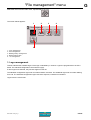
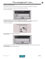
G - "File management" menu ............................................................................................ 93
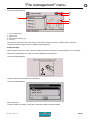
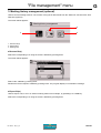
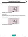
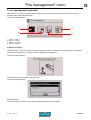
1. Logo management ............................................................................................................................... 93
Import a logo ................................................................................................................................... 94
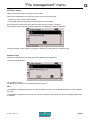
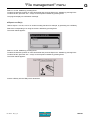
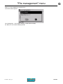
Export a logo (LO3 format) .............................................................................................................. 95
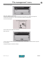
Number of logo segments ............................................................................................................... 96
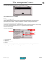
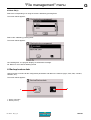
Re-index a logo ............................................................................................................................... 97
Delete a logo ................................................................................................................................... 97
2. Font management ................................................................................................................................ 98
Import a font .................................................................................................................................... 99
Export a font (PO3 format) ............................................................................................................ 100
Font version .................................................................................................................................. 101
Re-index a font .............................................................................................................................. 101
Delete a font .................................................................................................................................. 102
3. Marking history management (optional) ............................................................................................. 103
Rename file(s) ............................................................................................................................... 103
Export file(s) .................................................................................................................................. 103
Delete file(s) .................................................................................................................................. 105
4. Backup/restore data ........................................................................................................................... 105
Backup restoration ........................................................................................................................ 106
Memory backup ............................................................................................................................. 106
5. .csv management (optional) ............................................................................................................... 107
Import .csv file(s) ........................................................................................................................... 107
Export .csv file(s) ........................................................................................................................... 108
Rename .csv file(s) ....................................................................................................................... 109
Delete .csv file(s) ........................................................................................................................... 109
Ref. 92091 - P05_en_H
3/157
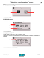
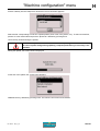
H - "Machine configuration" menu ................................................................................... 111
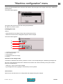
1. Security mode .................................................................................................................................... 111
Password ...................................................................................................................................... 112
"Supervisor" mode ........................................................................................................................ 112
"Operator" mode ........................................................................................................................... 113
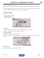
2. Time and date settings ....................................................................................................................... 114
Time and date settings .................................................................................................................. 114
Setting the clock ............................................................................................................................ 115
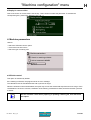
3. Display settings .................................................................................................................................. 116
Contrast ......................................................................................................................................... 116
Screen rotated 180° ...................................................................................................................... 116
Backlit screen ................................................................................................................................ 116
Display in reverse video ................................................................................................................ 117
4. Machine parameters ........................................................................................................................... 117
Off-limits control ............................................................................................................................ 117
Conversion of the units into inches ............................................................................................... 120
End marking type .......................................................................................................................... 120
5. Deleting all the files (reset) ................................................................................................................. 122
6. Language ........................................................................................................................................... 122
7. Update ................................................................................................................................................ 123
Software update ............................................................................................................................ 123
Power firmware update ................................................................................................................. 125
Activate an option .......................................................................................................................... 127
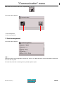
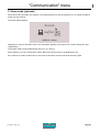
I - "Communication" menu ............................................................................................... 128
1. Serial management ............................................................................................................................ 128
Deactivate ..................................................................................................................................... 129
Raw data ....................................................................................................................................... 129
Connection to computer ................................................................................................................ 129
2. Slave mode (optional) ........................................................................................................................ 130
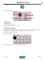
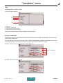
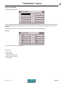
J - "Variables" menu ........................................................................................................ 131
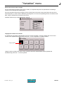
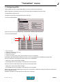
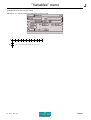
1. Configuring counters .......................................................................................................................... 131
Setting the batch number .............................................................................................................. 133
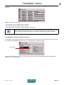
Setting of the counter’s reset ........................................................................................................ 134
2. Configuring variables .......................................................................................................................... 137
Programming within a marking file ................................................................................................ 137
Compiling a series of variables ..................................................................................................... 138
Copying the content of a variable .................................................................................................. 138
3. Configuring shifts ................................................................................................................................ 139
Copying the contents of a day of the week ................................................................................... 140
4. Configuring Day/Month/Year format ................................................................................................... 141
Year variable (YS) ......................................................................................................................... 141
Month variable (MS) ...................................................................................................................... 142
Day in the month variable (JS) ...................................................................................................... 142
Day of the week variable (DS) ...................................................................................................... 143
Hour variable (HS) ........................................................................................................................ 144
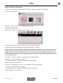
K - Use ............................................................................................................................ 146
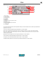
1. Marking process flowchart .................................................................................................................. 146
2. Initiation to marking ............................................................................................................................ 147
Step 1: Switching on the machine ................................................................................................. 147
Step 2: Creating a marking file ...................................................................................................... 148
Step 3: Graphic preview before marking ....................................................................................... 154
Step 4: Positioning the plate ......................................................................................................... 154
Step 5: Adjusting the height of the stylus ...................................................................................... 154
Step 6: Marking simulation ............................................................................................................ 155
Step 7: Marking the part ................................................................................................................ 156
L - Appendix .................................................................................................................... 157
Ref. 92091 - P05_en_H
4/157
A
Introduction
A
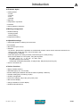
This manual corresponds to the 4.06 version of the program.
Some screenshots may be different from those displayed in the
program.
1. General characteristics of the program
The P05 standard marking program is integrated in a Control Unit, or in the main board of the machine (viewed on
an LCD screen). It is used to:
• program files for marking:
- set text
- variable text:
. date (using various set or customized formats)
. counter (incrementation, decrementation)
- logos
2. Program functions
Customization
• multilingual: program language selection
• "Supervisor" mode / "Operator" mode (access rights to certain functions or entry fields for text or coordinates)
• units (mm or inches)
Type of blocks
• marking:
- linear (choice of the angle)
- radial
• logos
• pilots a rotating third axis (DP3500/DP4500) for marking on circular parts
• pilots a motorized Z axis
Functions within the blocks
• delay between blocks (DELAY)
• marking of simple geometric shapes:
- circles
- lines
Ref. 92091 - P05_en_H
5/157
A
Introduction
A
Character styles
• marking effects:
- normal
- inverted
- mirror
- reflected
• alignment
• compression / expansion
• inclination
• spacing between characters
Marking management
• standard marking:
- marking N parts
- infinite marking
• independent marking
Adjustable settings
• customized speeds for marking and movement
• force (depth)
• date and time (CCU clock)
• variables:
- 10 numeric, alphanumeric, alphabetic or hexadecimal counters, which can be reset each time there is a
change in year, month, day, hour, day of the week, shift
- 10 alphanumeric variables
- shift codes (Q) set according to the day of the week (up to 5 shifts per day)
- date and time based on CCU system, using the keywords:
. DD - MM - YYYY - YY - Y - hh - mm - ss - WW - CCC
. m (mark first digit of the minutes)
. customized formats DS (day/week), JS (day/month), MS (month) and YS (year)
• choose a character font
Various functions
• display available memory
• download logos (LO3 - PLT format)
• transfer marking files between PC and the machine (Backup / Restore)
• simulate marking file (no marking on part)
• off-limits management
• set time for changing "day of the year" (CCC) code
• date and time display
• change orientation of screen display
• standard international font
Ref. 92091 - P05_en_H
6/157
A
Introduction
A
User memory
Available memory is 512 kB.
Several hundred files may be saved, depending on their size.
Maximum:
• 100 blocks per file
• 255 characters per block
Exchange of files via USB key
It is possible to import and export certain files via USB key (FAT32 file system only):
• marking file
• logos
• character font
Files must be located in the root directory of the file tree structure on the USB key. Do not place them in
directories.
3. Character encoding
Introduction
The previous marking programs used "8 bit" fonts, which could only contain 2 8 = 256 characters. The font change
was necessary for each language, display and marking were impossible for languages including over 256
characters.
Marking and display fonts used in the P05 program are "16 bit" programs, which may contain up to 216 = 65536
characters (less in practical terms, certain are reserved). These fonts are based on the setup of the characters of
the ISO/IEC 10646 standard, in the Basic Multilingual Plan. This standard, which specifies a set of universal
characters (Universal Character Set), also defines other characters (over 1.1 million). These are not generated by
the P05 program and must therefore not be used.
The 16 bit fonts are used to manage new languages and an increased compatibility with the actual operating
systems (Windows, Unix...). However, the numerous materials and applications still use the 8 bit fonts. In order to
have the best possible compatibility with these materials, the characters emitted and received by the program
(files or character strings) are encoded in UTF-8 (UCS Transformation Format, 8 bits). UTF-8 is used to represent
the 16 bit characters by using 8 bit codes. This font does not allow old 8 bit systems to manage 16 bit characters,
but it allows to manipulate the acceptable data and to transmit them with no loss of information.
UTF-8 encoding
UTF-8 was designed to be compatible with certain software initially foreseen for the processing of one-byte
characters. Each 16 bit character is encoded on a chain of 1 to 4 bytes.
UTF-8 is normalised in the RFC-3629 (UTF-8, a transformation format of ISO 10646). Encoding is also defined in
the 17 technical report of the Unicode standard. It is part of the standard on chapter 3 "Conformance" and is
approved by the International Standard Organisation (ISO), the Internet Engineering Task Force (IETF) as well as
most of the national standardization organisations.
Ref. 92091 - P05_en_H
7/157
A
Introduction
A
Encoding
The numbered characters from 0 to 127 are encoded on 1 byte(s) whose most significant bit is always 0.
The characters with a number greater than 127 are encoded over several bytes. In this case, the most significant
bits of the first byte form a series of 1 as long as the number of bytes used to encode the character, the following
bytes having 10 as the most significant bit.
Definition of the number of bytes used
UTF-8 binary representation
Meaning
0xxxxxxx
1 byte(s) coding 1 to 7 bits (from 0 to 127)
110xxxxx 10xxxxxx
2 byte(s) coding 8 to 11 bits (from 128 to 2047)
1110xxxx 10xxxxxx 10xxxxxx
3 byte(s) coding 12 to 16 bits (from 2048 to 65535)
11110xxx 10xxxxxx 10xxxxxx 10xxxxxx
4 byte(s) coding 17 to 21 bits (from 65536 to 2097151)
This idea could be applied up to 6 bytes but UTF-8 sets the limit to 4. This idea also allows the use of more bytes
than needed to code a character but the UTF-8 forbids it.
Note: The UTF-8 representation over 4 bytes corresponds to a character code greater than 65535, which
must not be used with the P05 program.
Example
Example of the UTF-8 encoding
Character
Character number
UTF-8 binary encoding
A
65
01000001
é
233
11000011 10101001
8364
11100010 10000010 10101100
In any UTF-8 character string, any 0 most significant bit byte encodes a US-ASCII character on a byte. The
characters whose codes are included between 0 and 127 are therefore represented the same way as in ASCII
(non-accentuated, capital and small letters, numbers and some frequent initials).
Practical consequences
The old systems using the ASCII 8 bit fonts may communicate with the P05 program, which uses 16 bit fonts. To
allow this interoperability, 2 methods are possible:
• The ASCII and UCS tables are common for the characters numbered from 0 to 127. For these characters, compatibility is guaranteed.
• For other characters, UTF-8 encoding is used to specify the 16 bit character code by using the sequences of
several 8 bit "characters", which can be managed by 8 bit systems.
Using the P05 program
As long as the program doesn’t exchange data with the exterior, it uses the 16 native bit fonts. The user can
benefit from extended linguistic support.
Ref. 92091 - P05_en_H
8/157
A
Introduction
A
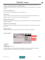
Manual editing of the marking files
The marking files (.tml files) in TML format (Technifor Marking Language) are saved in UTF-8 format. This format
is automatically recognized when a file is opened with Note Pad (notepad.exe) in Windows (2000 or more recent).
For an exact display, select a compatible display font, such as "Arial Unicode MS".
When saving, make sure the UTF-8 format is well selected (especially when creating a new file).
Data reception/emission (RS232, telnet)
The characters received must be encoded in UTF-8. Characters emitted are encoded in UTF-8.
If a device sends to the machine characters in ASCII encoding, they are only recognized if their codes are
included between 0 and 127. In this manner, this device may correctly receive the characters whose codes are
included between 0 and 127.
To use other characters, these must be encoded in UTF-8.
Example: To send the "é" character, the device cannot use the ASCII encoding of the Latin 1 character page
which assigns this character the code 130.
It must use UCS encoding which assigns it the code 133. In UTF-8, the code is written as follows: 11000011
10101001
It must thus send 2 bytes: 195 - 169.
DataMatrix
This format only allows the encoding of character strings of 8 bits. The internal strings of the program are thus
converted in UTF-8 before being encoded in DataMatrix, which enables encoding of all 16 bit characters to be
managed. The size of the DataMatrix needed for this encoding is greater than 8 bit character encoding as several
8 bit characters are needed to carry out UTF-8 encoding of a 16 bit character.
When the encoded characters have ASCII or UCS codes between 0 and 127, DataMatrix encoding is made in the
classic way and the size of the DataMatrix generated is the same.
Unicode
Unicode is an international standard which defines a set of universal characters, as in the ISO/IEC 10646
standard. The Unicode character codes correspond to those in the ISO/IEC 10646 standard and the Unicode
standard includes the ISO/IEC 10646 completely as a sub-set.
The Unicode standard adds to the ISO/IEC 10646 standard a representation model and complete word
processing, by assigning to each character a set of standardized or informative properties and by accurately
describing the semantic relations which may exist between several successive characters of a text. It also
standardizes the processing algorithms which preserve semantics of transformed texts to a maximum, while
spreading interoperability of the representation of these texts on heterogeneous systems.
This allows, for example, to specify the meaning of a text, so that two characters may be associated and form
one, etc...
Unicode management is complex and is not currently implemented in the P05 program. In the future, certain
Unicode rules will be added to the software, therefore allowing a partial support of Unicode according to needs.
Ref. 92091 - P05_en_H
9/157
A
Introduction
A
4. Starting-up the program
Check that the power cable is connected.
Turning on the CCU or the machine will launch the marking program.
A presentation screen will appear for a few seconds, followed by the main menu screen.
Check that the temperature is indeed between 5 0C (41 0F) and 45 0C (113 0F).
Turn off the machine before any intervention.
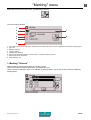
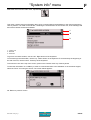
5. The different program menus
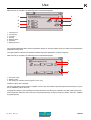
Main menu
The main menu is composed of 8 menus, each represented by an icon.
1
8
2
7
3
6
4
5
1 : "Marking" menu
2 : "Edit file" menu
3 : "Marking file management" menu
4 : "System info" menu
5 : "File management" menu
6 : "Machine configuration" menu
7 : "Communication" menu
8 : "Variables" menu
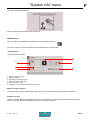
6. Functions of the keys used
The keyboard is used to access the different menus and program functions and to enter information necessary for
marking.
Use the Tab key or the Left - Right arrows to select the desired menu. The negative image of the selected icon will
appear. Validate by pressing Enter.
Ref. 92091 - P05_en_H
10/157
A
Introduction
A
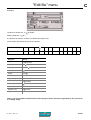
The keys most often used are:
13
12 11
10
1
2
3
4
5
6 7
3
8
9
1
Escape
Return to previous screen
2
Tab
3
Ctrl
Ctrl
Access to certain shortcuts using the keyboard
4
Alt
Alt
Access to certain shortcuts using the keyboard
5
Space
Activation / deactivation of the blocks, multi-selection of files to import/export
6
Context menu
Gives acces to the sub-menu bar in the "Edit file" menu, return to "Edit" mode,
travel from one part of the screen to the other within certain menus
7
Enter
Validation of the entered data, modifying a data entry zone, activation / deactivation of the radio button
8
Up - Down Left - Right
arrows
Move the cursor to different data entry areassetting the stylus position in the
"Stylus movement" function (F3)
9
Numeric
keypad
Esc
Access to various menus or tabs used to prepare a block
Num
Lock
7
/
*
8
9
PgUp
Home
4
5
1
2
End
6
Entering numeric values, incrementation / decrementation of numeric values
with the +/- keys, setting the stylus position in the "Stylus movement" function
(F3)
_
+
3
PgDn
.
0
Ins
Enter
Del
10
Page Up Page Down
Travel from one block to another during editing, setting the initial angle on the
rotary device in the (F3) function "Stylus movement", skipping pages in some
menus
11
Insert
Insert
12
Delete
Delete
13
Function keys
Insertion of an empty block in a marking file before the selected block, insertion
of a key word in the "Text" field
Deletion of a block from a marking file
Shortcuts to some functions in the program
F1
F12
Ref. 92091 - P05_en_H
11/157
A
Introduction
A
Functions with shortcuts
Certain functions can be obtained using a keyboard shortcut:
• Ctrl + Alt + I: display in reverse video - See page(s) 117
• Ctrl + Alt + F: screen rotated 180° - See page(s) 116
• Ctrl + Alt + B: activation / deactivation of backlightning - See page(s) 116
• Ctrl + Alt + A/Q: more or less contrast on the screen - See page(s) 116
• Ctrl + Alt + R: exit slave mode - See page(s) 130
• Ctrl + P: pause after a block - See page(s) 50
• Insert: insertion of an empty block in a marking file before the selected block - See page(s) 57
• Delete: deletion of a block from a marking file - See page(s) 58
• F2: marking preview - See page(s) 52
• F3: stylus movement - See page(s) 55
• F4: simulation of the current block - See page(s) 50
• F5: add a block at the end of the file - See page(s) 57
• F7: copy a block - See page(s) 58
• F8: view 1/3/5 blocks - See page(s) 51 - 52
• F9: simulate marking file (no marking on part) - See page(s) 50
• F10: file marked - See page(s) 49
• F11: save selected file - See page(s) 59
• F12: properties of the file - See page(s) 60
7. Use of graphic elements
Certain elements concerning graphic data are found at several points in the program. The entry mode for each is
as follows:
Incrementation / decrementation of the percentage using the +/- keys on the numeric
keypad
Incrementation / decrementation of the values using the +/- keys on the numeric
keypad or by manually typing them after pressing the Enter key
Radio button: activation / deactivation using the Enter key. It is possible to select just
one at a time
Drop down icon menu. Press Enter to scroll down, then on the Up - Down arrows of
the keyboard to navigate.
Drop down text menu. Press Enter to scroll down, then on the Up - Down arrows of
the keyboard to navigate. Quick search: type the first letter of the word you want to
search for.
Open text entry field. Press Enter to move to this field.
Ref. 92091 - P05_en_H
12/157
A
Introduction
A
8. Definition of a marking file
A marking file contains all the data to be marked on a part.
It may be composed of one or several lines.
In Pro-Pen jargon, a marking file is composed of marking blocks.
A marking block may contain alphanumeric text, a logo, a line, a
square...
A marking file can contain anywhere from 1 to 100 marking blocks.
The marking file used to create this plate contains 5 marking blocks.
The following pages describe the preparation of various types of
marking blocks.
9. Creating a marking file
To create a new marking file, use the arrows to select the "Edit file". Validate by pressing Enter.
Select the "Create a new file" icon. Validate by pressing Enter.
An empty block will appear. Press Enter to enter data. See: "Preparing a marking block".
Ref. 92091 - P05_en_H
13/157
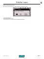
B
"Marking" menu
B
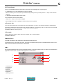
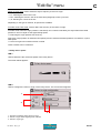
Select this menu from the main menu, represented by the icon:
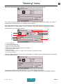
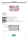
The screen below appears:
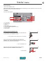
1
2
7
3
4
5
8
6
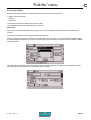
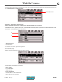
1 : Icon used to return to the main menu, followed by the name of the menu. This icon appears several times in the program.
2 : Open file
3 : Marking "N times"
4 : "Infinite" marking
5 : "Independent" marking
6 : Pop-up help associated with the current function. This field is always present.
7 : Name of the file to be opened
8 : "Start marking" icon
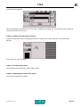
1. Marking "N times"
Used to mark the same marking file a set number of times
Select the number of markings requested. The default value is 1.
Use the arrows to select the "Open" icon. Validate by pressing Enter. Choose the file to be marked. Validate by
pressing Enter.
Ref. 92091 - P05_en_H
14/157
A
"Marking" menu
B
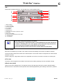
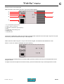
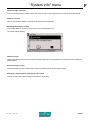
Move to the "Start marking" icon. Validate by pressing Enter. The screen below appears:
This screen provides information concerning the file to be marked and the status of the marking. The cursor is
positioned on the "Start marking" icon. Validate by pressing Enter.
Note: Triggering the marking can be also carried out by closing the "Start marking" contact present on the
appropriate connector of the machine. For more information, consult the manual of the machine in question.
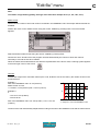
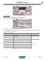
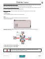
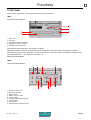
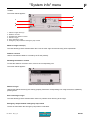
During marking, the screen below appears:
6
1
7
2
8
3
4
5
9
1 : "Stop marking" icon
2 : "Pause during marking" icon
3 : Text for the block being marked
4 : Name of the block being marked
5 : Marking time. Appears once the markings are completed.
6 : Name of the file being marked
7 : Status of marking
8 : Number of markings carried out in relation to the total number of markings to be done
9 : Current time and date
To pause marking, place the cursor on the corresponding icon. Validate by pressing Enter. Marking is interrupted.
The screen below appears:
The cursor is located on the "Restart marking" icon. To restart marking, press Enter.
To stop marking, place the cursor on the "Stop marking" icon. Validate by pressing Enter. Marking is stopped.
Ref. 92091 - P05_en_H
15/157
A
"Marking" menu
B
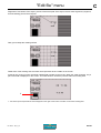
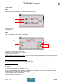
At the end of the marking, the screen indicates the marking time.
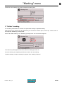
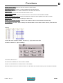
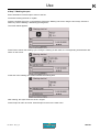
2. "Infinite" marking
It is a marking mode similar to "N times" except that the marking is repeated infinitely.
Select the file to be opened using the up/down keys To access the "Infinite" option, use the Up - Down arrows on
the keyboard. Validate by pressing Enter.
Move to the "Start marking" icon. Validate by pressing Enter. The screen below appears:
The "Infinite" symbol appears next to the number of markings carried out.
Once one marking is completed, press Enter to launch the next marking.
To pause marking or stop the marking in progress: See: "Marking "N times"".
Ref. 92091 - P05_en_H
16/157
A
"Marking" menu
B
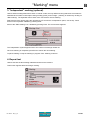
3. "Independent" marking (optional)
Used to obtain markings identical to those in "Infinite" mode, the only difference being that when the machine is
switched back on after an interruption during marking (reset, power outage...) marking is resumed by clicking on
"Start marking". The keyboard doesn’t have to be connected to resume marking.
Select the file to be opened using the up/down keys To access the "Independent" option, use the Up - Down
arrows on the keyboard. Validate by pressing Enter.
Move to the "Start marking" icon. Validate by pressing Enter. The screen below appears:
The "Independent" symbol appears next to the number of markings carried out.
Once one marking is completed, press Enter to launch the next marking.
To pause marking or stop the marking in progress: See: "Marking "N times"".
4. Repeat last
Used to execute the last marking realized and saved in the machine.
This function appears after launching a marking.
Ref. 92091 - P05_en_H
17/157
C
"Edit file" menu
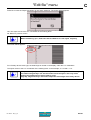
C
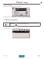
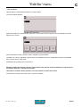
Select this menu from the main menu, represented by the icon:
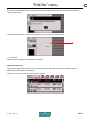
The screen below appears:
1
2
3
1 : Create a new marking file
2 : Open the last file used
3 : Open an existing file
Create a new marking file
Gives access to an "empty" marking file to prepare marking blocks. See: "Preparing a marking block".
Open the last file used
Used to directly open the last file used. If there is no file in memory, the following message appears:
Go to "Create a new file" to prepare blocks for a new file.
Ref. 92091 - P05_en_H
18/157
A
"Edit file" menu
C
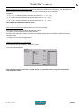
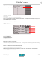
Open an existing file
Used to open a specific file. The screen below appears:
Choose the file to be opened using the Up - Down arrows. Validate by pressing Enter.
1. Preparing a marking block
To access the sub-menu bar at the top of the screen, press the Context menu key on
the keyboard.
See: ""Edit" menu sub-menus"
When a file is created, an empty block appears on the screen.
Ref. 92091 - P05_en_H
19/157
A
"Edit file" menu
C
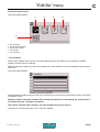
TAB 1:
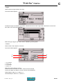
Press Enter to prepare the block. The first data entry screen appears (tab 1).
7
8
9
1
2
3
10
4
11
5
12
6
1 : Block number
2 : Type of marking
3 : Text to be marked
4 : X coordinate
5 : Text angle
6 : Marking force
7 : Save block and return to previous screen
8 : File name
9 : Block name (label)
10 : Number of the data entry screen (tab)
11 : Character size
12 : Y coordinate
At any time during the preparation of a block:
• Press the Page Up - Page Down arrows on the keyboard to move from one block to
another in a marking file. The cursor appears on the same data entry block as the
one for the block in progress except that it’s the next block.
• Press the Tab key to move from one tab to another within the same block.
Block number
Each block is identified by a number. This number evolves automatically when blocks are added or deleted.
The first number indicates the number of the selected block. The second number corresponds to the total number
of blocks in the file.
Press the Page Up - Page Down arrows on the keyboard to move from one block to another in a marking file.
File name
The name of the file appears in this filed if it has been saved. While preparing a new file, this field is empty.
Block name (label)
Used to name each marking block. This optional, free access data entry field can be used to add information
about the block or instructions for the operator which will be diplayed during the marking of the block in question.
Ref. 92091 - P05_en_H
20/157
A
"Edit file" menu
C
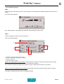
Type of marking
This field defines the type of marking to be carried out in the block being prepared.
Certain types of marking involve new data entry fields.
To access this data entry field, use the arrows on the keyboard. Validate by pressing Enter. The screen below
appears:
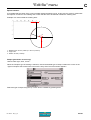
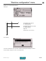
Select the desired type of marking using the Up - Down arrows. Linear marking is selected by default.
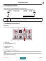
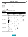
Linear marking
Used to mark straight lines of text at an angle.
To obtain a marking parallel to the X axis, set the angle at 0° in the corresponding (5) field.
To obtain a marking parallel to the Y axis, set the angle at 90°.
0
0
10
20
30
0
0
10
20
30
X
X
0
0
20
10
X
10
10
10
20
90°
45°
30
20
Y
Y
Angle: 0°
Ref. 92091 - P05_en_H
Angle: 45°
Y
Angle: 90°
21/157
A
"Edit file" menu
C
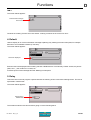
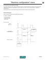
Radial marking
Used to obtain texts along the circumference of a circle. When this type of marking is selected, a new field (1) for
entering the circle radius value appears on the screen.
The angle value in degrees corresponds to the positioning angle of the marking on the circle.
The X-Y coordinates correspond to the center of the base circle for the marking.
A new icon (2), used to choose the marking direction, appears at the bottom right side of the screen.
1
2
1 : "Radius" field
2 : Marking direction icon
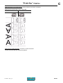
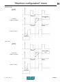
Clockwise marking / counter-clockwise marking
In radial marking mode, select the marking direction icon with the arrows in order to select clockwise or counterclockwise marking. Clockwise marking is selected by default.
Initial angle
Clockwise marking
Angle: 90°
Centering
Counter-clockwise marking
X
X
90°
90°
Y
Y
Angle: 270°
Centering
X
X
270°
270°
Y
Ref. 92091 - P05_en_H
Y
22/157
A
"Edit file" menu
C
Special situation
It is possible that the center of the circle is located outside the marking zone. In this case, the X and Y coordinates
are superior or inferior to the marking area. Check that the text to be marked is within the marking area.
Example of a circle outside the marking area:
1
2
3
1 : Marking area: 60 mm (2.362 in) x 40 mm (1.575 in)
2 : Angle: 160°
3 : Radius: 50 mm (1.969 in)
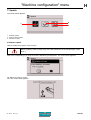
Shapes (pneumatic version only)
Used to mark logos, lines, circles...
When the "Shapes" type of marking is selected, choose the desired type of shape. Position the cursor on the
"Types of shapes" field. Press Enter to access the entry field. The screen below appears:
Select the type of shape using the Up - Down arrows. Validate by pressing Enter.
Ref. 92091 - P05_en_H
23/157
A
"Edit file" menu
C
• Logos
Used to mark the logos saved in the CCU.
The screen below appears:
To select the logo to be marked, go to tab 2. Position the cursor on the "Logo" field. Press Enter to access the
entry field. The screen below appears:
Select the logo using the Up - Down arrows. Validate by pressing Enter.
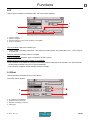
• Circles
Used to mark circles, ellipses, circle arcs.
The screen below appears:
1
2
3
4
1 : X coordinate
2 : Radius in X
3 : Y coordinate
4 : Radius in Y
Select the circle’s radius in X and Y.
To trace a circle, the radius in X and Y values must be identical.
To trace an ellipse, the radius in X and Y values must be different.
Vertical ellipse: radius in X < radius in Y
Horizontal ellipse: radius in X > radius in Y
Ref. 92091 - P05_en_H
24/157
A
"Edit file" menu
C
Once all these fields are filled, use the keyboard’s Tab key or arrows to switch to tab 2 in order to proceed with the
preparation of the block. The screen below appears:
1
2
3
1 : Initial angle (degrees)
2 : End angle (degrees)
3 : Marking direction
To mark an ellipse, an additional field appears on the screen.
4
4 : Inclination (angle in degrees)
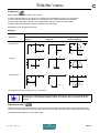
Sample instructions for obtaining a circle:
TAB 1:
TAB 2:
Marking obtained:
0
5
10
15
X
5
10
15
X = 10 mm
Y = 10 mm
Radius in X = 5 mm
Radius in Y = 5 mm
Y
Ref. 92091 - P05_en_H
25/157
A
"Edit file" menu
C
Sample instructions for obtaining a horizontal oval:
TAB 1:
TAB 2:
Marking obtained:
0
5
10
15
X
5
X = 10 mm
Y = 10 mm
Radius in X = 8 mm
Radius in Y = 5 mm
10
15
Y
Sample instructions for obtaining a curved line:
TAB 1:
TAB 2:
Marking obtained:
0
5
10
15
X
5
45°
10
15
180°
X = 10 mm
Y = 10 mm
Radius in X = 5 mm
Radius in Y = 5 mm
Initial angle: 45°
End angle: 180°
Y
Ref. 92091 - P05_en_H
26/157
A
"Edit file" menu
C
• Lines
Used to mark one or several lines.
The screen below appears:
1
1 : Marking direction
Once all these fields are filled, use the keyboard’s Tab key or arrows to switch to tab 2 in order to proceed with the
preparation of the block. The screen below appears:
2
3
2 : X-Y coordinates of point 1
3 : X-Y coordinates of point 2
It is possible to choose up to 16 points to establish one or several lines.
To insert a point below the selected point, press the Insert key on the keyboard.
To add a point at the end of the list, press on the F5 key on the keyboard.
To delete a point, press Delete key on the keyboard.
Sample instructions for obtaining a slanted line:
TAB 1:
Ref. 92091 - P05_en_H
TAB 2:
27/157
A
"Edit file" menu
C
Marking obtained:
0
5
10
15
X
5
10
15
Y
Sample instructions for obtaining a series of lines:
TAB 1:
TAB 2:
Marking obtained:
0
5
10
15
20
X
5
10
15
Y
Ref. 92091 - P05_en_H
28/157
A
"Edit file" menu
C
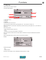
2D code (optional)
Used to mark DataMatrix codes.
When the "2D code" marking type is selected, choose the desired type of code. Position the cursor on the "Code
types" field. Press Enter to access the entry field.
• DataMatrix
The screen below appears:
4
5
6
7
8
1
2
3
1 : X-Y coordinates
2 : Angle in degrees
3 : Cell size
4 : Matrix format
5 : Size of the DataMatrix code (height)
6 : Spiral marking (electromagnetic version only)
7 : One way marking
8 : Return marking
Position and size of the DataMatrix code:
0
10
X
X-Y coordinates: the values entered in the X and Y fields determine
the start position of the DataMatrix marking.
1 : The X represents the start marking point (X-Y coordinates).
50
X
Y
1
Size: the value entered in this field defines the height of the
DataMatrix code. This value automatically adapts itself according
to the size of the cells and the matrix format.
X
0
1
1 : Size of the DataMatrix code
Y
Angle: the value entered in this field determines the angle in
degrees along which the DataMatrix code is marked.
X
0
1
1 : Angle in degrees
Y
Ref. 92091 - P05_en_H
29/157
A
"Edit file" menu
C
Note
To maintain a high marking quality, the angle value must be a multiple of 90° (0°, 90°, 180°, 270°).
Matrix format:
Determines the number of lines and columns contained in the DataMatrix code. Several pre-defined formats are
available.
Position the cursor on the "Matrix format" using the arrows. Validate by pressing Enter. The screen below
appears:
Select the desired matrix format using the arrows. Validate by pressing Enter.
Choose the "Auto" format to have the program calculate automatically the number of lines and columns
necessary to encode the text to be marked.
When the matrix format selected does not allow the representation of the text to mark, a warning symbol appears
in the lower right corner of the screen.
Cell size:
To know the height of the cells which make up the code, divide the size of the code by the number of lines in the
format selected.
Example 1:
Size of the DataMatrix code: 10 mm (0.394 in)
Matrix format: 20 x 20
=> cell size: 10 mm (0.394 in)/20 = 0.5 mm (0.02 in)
Example 2:
If:
2
1
- cell = 0.67 mm (0.026 in)
- format: 20*20
Size of the DataMatrix code: 0.67 mm (0.026 in) x 20 = 13.4 mm
(0.528 in)
1 : Size of the DataMatrix code
2 : Height of a cell in the DataMatrix code
The size of the cells automatically adapts itself according to the size of the DataMatrix code and the matrix format.
Ref. 92091 - P05_en_H
30/157
A
"Edit file" menu
C
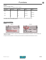
One way marking / return marking / spiral marking:
One way marking: the stylus always restarts from the left at the beginning of each line. It favors mark quality over
speed.
Return marking: the stylus marks the first line of the code from left to right, then the second from right to left, etc...
It favors the marking speed.
Spiral marking (electromagnetic version only): marking starts with the "L" of the code then the data zone is
marked in a spiral. This marking mode can reach a high speed without the marking quality deteriorating.
Select one box or the other. Validate by pressing Enter.
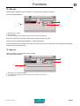
To enter other information specific to DataMatrix, go to tab 2. The screen below appears:
Text to be marked
Text to be marked:
Insert the text to be encoded in DataMatrix.
The processing of non-printable 04 - 29 - 30 characters is authorized (U_ID). To insert them, use the
corresponding ASCII codes.
In the event of missing or too long text in relation to the size of the code selected, a warning symbol appears in the
lower right corner of the screen.
Ref. 92091 - P05_en_H
31/157
A
"Edit file" menu
C
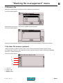
• QRCode / Micro QRCode / IQRCode
The screen below appears:
4
1
5
2
3
6
7
1 : X-Y coordinates
2 : Angle in degrees
3 : Cell size (QRCode / Micro QRCode)
4 : Matrix format
5 : Code size (height)
6 : One way marking
7 : Return marking
Code position and size:
0
10
X
X-Y coordinates: the values entered in the X and Y fields determine
the start position of the marking.
1 : The X represents the start marking point (X-Y coordinates).
50
X
Y
1
Size: the value entered in this field determines the height of the
code. This value automatically adapts itself according to the size of
the cells and the matrix format.
X
0
1
1 : Code size
Y
Angle: the value entered in this field determines the angle in
degrees along which the code is marked.
X
0
1
1 : Angle in degrees
Y
Note
To maintain a high marking quality, the angle value must be a multiple of 90° (0°, 90°, 180°, 270°).
Ref. 92091 - P05_en_H
32/157
A
"Edit file" menu
C
Matrix format:
Determines the number of lines and columns contained in the code. Several pre-defined formats are available.
Position the cursor on the "Matrix format" using the arrows. Validate by pressing Enter. The screen below
appears:
Select the desired matrix format using the arrows. Validate by pressing Enter.
Choose the "Auto" format to have the program calculate automatically the number of lines and columns
necessary to encode the text to be marked.
When the matrix format selected does not allow the representation of the text to mark, a warning symbol appears
in the lower right corner of the screen.
Cell size (QRCode / Micro QRCode):
To know the height of the cells which make up the code, divide the size of the code by the number of lines in the
format selected.
Example 1:
Code size: 10 mm (0.394 in)
Matrix format: 21 x 21
=> cell size: 10 mm (0.394 in)/21 = 0.48 mm (0.019 in)
Example 2:
If:
- cell = 0.67 mm (0.026 in)
- format: 20*20
Code size: 0.67 mm (0.026 in) x 20 = 14.07 mm
(0.554 in)
The size of the cells automatically adapts itself according
to the size of the code and the matrix format.
Ref. 92091 - P05_en_H
Micro QR Code
33/157
A
"Edit file" menu
C
One way marking / return marking:
One way marking: the stylus always restarts from the left at the beginning of each line. It favors mark quality over
speed.
Return marking: the stylus marks the first line of the code from left to right, then the second from right to left, etc...
It favors the marking speed.
Select one box or the other. Validate by pressing Enter.
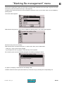
To enter other information specific to this type of block, go to tab 2. The screen below appears:
1
2
4
3
1 : Text to be marked
2 : Level of error corrector
3 : Compression (IQRCode)
4 : Code shape (IQRCode)
Text to be marked:
Insert the text to be encoded.
In the event of missing or too long text in relation to the size of the code selected, a warning symbol appears in the
lower right corner of the screen.
Level of error corrector:
Select the corrector level required.
Compression (IQRCode):
The data can be compressed in the code (IQRCode).
To activate the corresponding box, press Enter.
Code shape (IQRCode):
Select the type of shape using the Up - Down arrows. Validate by pressing Enter.
Ref. 92091 - P05_en_H
34/157
A
"Edit file" menu
C
Function
Used to access to certain automation functions, operations on the variables, etc.
Some functions are optional.
For a detailed description of the marking functions: See: Functions (67)
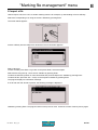
Rotary device (optional)
Used to mark cylindrical parts thanks to a rotary marking device.
This block type is viewed on the screen only if the device is installed on the machine.
Two new data entry fields appear on the screen.
1
2
1 : Initial angle (degrees)
2 : Part radius (mm)
Initial angle: used to define the reference angle of the marking on the rotary device. Depending on the alignment
selected, the marking will be left or right aligned or centered in relation with this angle.
Part radius: used to adapt the marking to the type of part underway.
To enter other information specific to the rotary device, go to tab 2. The screen below appears:
1
2
1 : Writing direction on the rotary device
2 : Rotary device rotation direction
Ref. 92091 - P05_en_H
35/157
A
"Edit file" menu
C
Writing direction on the rotary device: used to determine character orientation.
Rotary device positioned on the origin side
Clockwise
Counter-clockwise
Rotary device rotation direction: clockwise / counter-clockwise
Counter-clockwise direction selected by default.
Ref. 92091 - P05_en_H
36/157
A
"Edit file" menu
C
Motorized Z-axis (option available on machines P5000Z only)
This type of block is used to control the motorized Z axis and adjust the Z distance (Z min: 0 mm - Z max:
280 mm).
This block type is viewed on the screen only if the device is installed on the machine.
The screen below appears:
1
3
2
1 : Options for the Z axis
2 : Absolute distance / relative distance
3 : Z distance
Options for the Z axis: select the option required.
- Movement: used to displace the Z axis to the required distance. Use this mode when the coordinates to be
reached are known.
- Sensing: used to detect automatically the surface of the part to be marked (electromagnetic version only). Use
this mode when the position of the surface to be marked is not known.
Absolute distance / relative distance: select the option required.
- absolute distance: the distance is calculated from the origin of the axes (on top of the Z axis).
- relative distance: the distance is calculated from the current coordinates.
Z distance: select the Z distance to reach.
Remarks:
• During sensing or movement before marking, simultaneously press the 2 buttons on the sides of the machine
table (two-hand control).
• In "Sensing" mode, do not leave the stylus activated (point out of the stylus) for more than 5 mn so as not to
damage the electromagnet.
New fields appear on the screen in "Sensing" mode.
1
2
1 : Distance between the stylus and the part
2 : Fast mode / accurate mode
Ref. 92091 - P05_en_H
37/157
A
"Edit file" menu
C
Distance between the stylus and the part: used to adjust the Z distance after sensing the part. By default, the
distance between the stylus and the surface is 3 mm. This distance can be changed.
Examples:
• If: Z = -1.00 => distance between the stylus and the part = 3 - "-1" = 4 mm
• If: Z = 0.00 => distance between the stylus and the part = 3 - "0" = 3 mm
• If: Z = 1.00 => distance between the stylus and the part = 3 - "1" = 2 mm
Note: Maximum adjustment distance: 6 mm
Fast mode / accurate mode: used to define the accuracy of sensing.
Fast mode: sensing of the part takes place at high speed.
=> sensing is less accurate but cycle time is shorter
Accurate mode: when the position is reached, the marking head leaves this position to repeat the sensing
operation slowly.
=> seeking the accurate sensing position
Using the F3 function in a "Z axis" block
The F3 function is only possible in "Movement" mode.
The screen below appears:
Height adjustment: using the +/- keys on the numeric keypad
Note: when using the F3 function in a linear block, it is possible to move along Z but only the X-Y
coordinates are saved.
Ref. 92091 - P05_en_H
38/157
A
"Edit file" menu
C
Text to be marked
Enter the text to be marked in the appropriate block. The text may be composed of:
• capital / lower case letters
• numbers
• key words
The maximum number of characters per block is 255.
The characters that can be marked depend on the font.
Key words
Key words are codes interpreted by the program. They are not actually marked but rather "recorded" before
marking.
It is possible to define several keywords in the same text area.
To enter a keyword, press the Insert key on the keyboard in the "Text" area. The list of keywords appears. Select
the desired keyword using the Up - Down arrows or by typing the first letter of the keyword to be inserted. Validate
by pressing Enter.
The keywords are indivisible units. When a keyword is inserted, it appears in a frame, it is impossible to delete
part of akeyword. Each keyword is considered a single character.
Ref. 92091 - P05_en_H
39/157
A
"Edit file" menu
C
For Kn - Vn - FKn - FVn keywords, a second window appears to select the variable number.
Splitting a variable
A portion of the contents of a variable may be selected and marked.
When a variable is inserted in text, the screen below appears:
To mark all the content of the variable, leave the brackets empty.
To mark part of the content of the variable, indicate between brackets the first and last character to take into
account, separated by a semi-colon (;).
Characters (syntax: Vn[a;b])
Possible values
Meaning
Note
N
N character
0 < N < 256
0
last character
0!
last character (not included)
&u
first character for which the Unicode is u
&u!
first character for which the Unicode is u (not included)
#u
last character for which the Unicode is u
#u!
last character for which the Unicode is u (not included)
%u
first character for which the Unicode is not u
%u!
first character for which the Unicode is not u (not included)
*u
last character for which the Unicode is not u
*u!
last character for which the Unicode is not u (not included)
0 < u < 65536
Ref. 92091 - P05_en_H
40/157
A
"Edit file" menu
C
Examples:
Contents of variable V3: "7 0 2$ 4b00z"
Marking obtained: " 0 2$ "
It is possible to mark the content of a variable from right to left.
The 0 number represents the end of the variable.
Characters:
Code: Unicode
7
Space
0
55
32
48
Examples
Result
V0[ ]
70
2$ 4b00z
V0[1;0]
70
2$ 4b00z
V0[0!;1]
00b4 $2
V0[4;10]
8364
2
$
Space
4
b
0
0
z
50
36
32
52
98
48
48
122
07
2$ 4b0
V0[8;3]
4 $2
V0[&50;10]
2$ 4b0
V0[&50;&98!]
2$ 4
V0[&48;0]
0
V0[4;&98]
0
2$ 4b00z
2$ 4b
V0[#32!;0]
4b00z
V0[%55!;*122]
0
V0[&8364!;*122!]
2$ 4b0
2$ 4b00
Note: if it is not possible to determine the result (string too short, character sought absent, etc.), the result
is an empty string.
Ref. 92091 - P05_en_H
41/157
A
"Edit file" menu
C
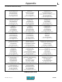
List of key words
Key words
Definition
Marking
DD
number of the day in the month (from 01 to 31)
09 - for the 9th day in the month
MM
month number (01 to 12)
05 - for the month of May
YYYY
year in 4 digit(s)
2007
YY
year in 2 digit(s)
07
Y
year in 1 digit(s)
7
hh
hours (00 to 23)
12 - for 12 h 28 min 35 sec
mm
minutes (00 to 59)
28 - for 12 h 28 min 35 sec
m
first number for block of ten minutes (1 to 5)
2 - for 12 h 28 min 35 sec
ss
seconds (00 to 59)
35 - for 12 h 28 min 35 sec
WW
week number (01 to 53)
01 - for January 3 2001
CCC
number of the day in the year (001 to 366)
028 - for January 28 2001
HS
time interpretation code
DS
interpretation code for the day of the week
JS
interpretation code for the day of the month
MS
interpretation code for the month
YS
interpretation code for the year
Kn
interpretation code for the counters (machine counter(s))
Q
interpretation code for shifts according to time block
Vn
interpretation code for variables (machine variable(s))
FVn
interpretation code for variables (file variable(s))
See: "File variable(s)"
FKn
interpretation code for the counters (file counter(s))
See: "File counter(s)"
Vm
last text marked
MAC
MAC address
IP
IP address
SN
serial number
UN
name of the machine (Control Unit)
HN
marking head name
CM
number of markings already carried out
NM
number of markings to execute
SYMBOLS
common symbols
See: “"Variables" menu”
Ref. 92091 - P05_en_H
42/157
A
"Edit file" menu
C
X-Y coordinates
The X-Y coordinates determine the position of the text in the marking area. They are given:
• in millimeters or in inches, depending on the unit chosen
• with an accuracy of 0.1 mm (0.01 in) in manual entry mode (0.5 mm (0.02 in) with the +/- keys on the numeric
keypad)
• in absolute value with relation to the origin
The coordinates can be entered either:
• using the +/- keys on the numeric keypad
• by pressing Enter then by typing the value directly on the keyboard
Character size
The "Size" field defines the actual height, in either millimeters or inches, of characters marked in capital letters.
The size can range from 0.5 mm (0.02 in) to 100 mm (3.937 in). The accuracy is to 0.01 mm (0.001 in) in manual
entry mode (0.1 mm (0.01 in) with the +/- keys on the numeric keypad).
The default value is 2.5 mm (0.10 in).
Text angle
Used to define the angle at which the text is marked. See: “Linear marking”.
The default value is 0°.
Marking force
The width and depth of the marked line varies with the defined value.
The higher the force, the deeper the mark. This value is expressed as a percent. The default value of the "Force"
area varies according to the machine’s configuration.
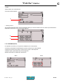
TAB 2:
Once all these fields are filled, use the keyboard’s Tab key or arrows to switch to tab 2 in order to proceed with the
preparation of the block. The tab number appears in reverse video.
1
5
2
6
3
7
4
1 : Character font
2 : Compression
3 : Inclination
4 : Spacing
5 : Marking effects
6 : Alignment
7 : Marking direction
Ref. 92091 - P05_en_H
43/157
A
"Edit file" menu
C
Character font
The various fonts saved are identified by a number followed by their name. Go to the font area to select the
character font to be used in the marking block being prepared.
List of available fonts
Standard character fonts
Pneumatic machines
0: Standard font
Electromagnetic
machines
X
X*
(optional)
X
2: Simplified font
X
not available
3: 5x7 font
X
X
4: OCR-A font
(optional)
not available
5: OCR-B font
(optional)
not available
7: Double stroke font
(optional)
not available
8: Low density EM font
(optional)
(optional)
9: Medium density EM font
(optional)
(optional)
10: High density EM font
(optional)
(optional)
1: Standard EM font
* See: Dot density per millimeter (electromagnetic version only)
Note: for the list of characters available, contact Pro-Pen.
Compression
Used to modify character width without modifying their height. The compression factor modifies the space
between the characters. This value is expressed as a percent. It must be between 25% and 300%, with
increments of 5%. The default value is 100%.
Compression 50%:
Compression 100%:
Compression 150%:
Inclination
Used to determine the value, in degrees, of the inclination angle of the characters in relation to the vertical. It must
be between -85° and +85°, with increments of 5°. If the value is positive, the characters slant right. If the value is
negative, the characters slant left. The default value is 0°.
Inclination -30°:
Inclination 0°:
Inclination +30°:
Ref. 92091 - P05_en_H
44/157
A
"Edit file" menu
C
Spacing
Used to modify the inter-character spacing, without changing their width or height. This value is expressed as a
percent. It must be between 25% and 300%, with increments of 5%. The default value is 100%.
Spacing 50%:
Spacing 100%:
Spacing 150%:
Marking effects
Several marking directions are proposed in order to adapt marking to the specificities of certain parts.
In radial mode, only the normal and mirror effects are available.
Marking obtained:
Result
Marking effects
Normal
Linear marking
Angle: 0°
10
0
0
20
X
x
10
0
10
20
X
10
20
X
0
0
0
10
x
Y
0
0
0
10
Y
Mirror: symmetry
along Y
Radial marking
Centering
Angle: 90°
Linear marking
Angle: 35°
10
20
10
20
X
x
Y
0
10
20
X
0
0
X
x
x
10
Y
Inverted: symmetry
along X-Y
0
0
10
10
10
Y
Y
0
20
X
10
x
20
0
X
x
x
10
10
Y
Reflected: symmetry
along X
0
Y
0
10
10
20
X
0
0
10
20
X
x
Y
10 x
Y
The X represents the start marking point (X-Y coordinates).
Ref. 92091 - P05_en_H
45/157
A
"Edit file" menu
C
Alignment
Used to align the text to the left, right or center.
In case of left alignment to, the value of X corresponds to the beginning of the text to be marked.
In case the text is centered, the value of X corresponds to the center of the text to be marked.
In case of right alignment, the value of X corresponds to the end of the text to be marked.
In radial mode, text justification is done in relation to the start angle.
By default, the text is aligned to the left.
Examples
Result
Alignment
Linear marking
Angle: 0°
Linear marking
Angle: 45°
Radial marking
Clockwise marking
0
0
Left alignment
10
20
30
40
0
X
10
0
30
20
40
0
10
X
20
30
40
30
40
30
40
X
x
10
10
0
90°
20
x
0
20
x
0
Centering
0
10
20
X = 20 mm
Angle: 90°
X = 20 mm
X = 20 mm
30
40
0
X
10
0
30
20
40
X
0
0
10
20
X
10
10
10
20
x
20
20
90°
x
x
X = 20 mm
0
Right alignment
0
0
10
20
X = 20 mm
Angle: 90°
X = 20 mm
30
40
10
0
20
30
X
40
X
0
0
10
20
X
10
10
10
90°
20
20
Y
x
20
Y
X = 20 mm
x
X = 20 mm
x X = 20 mm
Angle: 90°
The X represents the start marking point (X-Y coordinates).
The text to be marked may become off-limits if the X or Y value, or the character size,
is too large. To correct this anomaly, reduce or increrase one or the other of these
values.
Marking direction
Used to choose the movement direction of the stylus during marking, from left to right or from right to left. This
function is used to optimize marking time and must not be confused with the direction of writing (marking effects).
The default marking direction is from left to right.
Ref. 92091 - P05_en_H
46/157
A
"Edit file" menu
C
In the following example, the marking direction from right to left reduces the movements of the stylus between the
first block and the second one.
1 : Marking direction from left to right for the 2 blocks
2 : Marking direction from right to left for the second block
3 : Segments of movement of the stylus
TAB 3:
Once all these fields are filled, use the keyboard’s Tab key or arrows to switch to tab 3 in order to proceed with the
preparation of the block.
1
2
3
1 : File speed option
2 : Marking speed
3 : Dot density per millimeter (electromagnetic version only)
File speed option
If this option is activated, the speeds chosen for the file in the sub-menu "File - Properties" are applied to the
block.
When the option is activated, it is impossible to modify the values on screen. To customize the speeds in the
block, deactivate this option by pressing Enter.
This option is activated by default.
To choose the speeds of the file: See: "Properties of the file (F12)"
Marking speed
Used to determine the speed of the stylus.
This value must be between 1 and 10. The default value is 6. From 1 to 7, speed increases with an optimum
quality of marking. From 8 to 10, quality gradually decreases in order to privilege speed. The faster the marking,
the lower the quality. A very high quality marking requires a slow marking speed.
Ref. 92091 - P05_en_H
47/157
A
"Edit file" menu
C
Dot density per millimeter (electromagnetic version only)
Used to define the number of dots per millimeter produced by the stylus, in electromagnetic.
Electromagnetic machines: preference should be given to the use of electromagnetic dot by dot fonts. For
marking certain characters, a continuous line font can be used. In this case, adjust the density of the points.
The higher the density, the closer the dots are to each other. The default value is 3.
As speed increases, the density of dots per millimeter becomes limited.
2. "Edit" menu sub-menus
Once the preparation of the block is complete, move to the "OK" button using the keyboard’s arrow keys or press
Esc to validate the block and exit.
The program returns to the marking file and the sub-menus can then be accessible using the Context menu key
on the keyboard.
They are used to edit the file in progress.
To switch from one menu to another, use the Left - Right arrows.
To scroll a menu, press Enter or the Down arrow. If the functions are not fully displayed in the sub-menu, the
description is shown in the pop-up help bar at the bottom of the screen.
To close a menu, press the Up arrow.
To return to the blocks and exit sub-menus, press the Context menu key on the keyboard.
5
4
3
2
1
1 : "Marking" sub-menu
2 : "View" sub-menu
3 : "Edit" sub-menu
4 : "File" sub-menu
5 : Back to the previous menu
Ref. 92091 - P05_en_H
48/157
A
"Edit file" menu
C
"Marking" sub-menu
Used to access certain functions of the "Marking" menu directly from the file.
1
2
3
4
5
6
1 : Marking a file
2 : Access to the "Marking" menu
3 : Marking simulation
4 : Marking simulation with pause
5 : Simulation of the current block
6 : Simplified simulation
Marking a file (F10)
Used to mark the file in progress "one time".
The screen below appears:
Press Enter to launch the marking cycle. During the marking of each block, the corresponding characteristics are
shown on the screen.
6
1
7
2
8
3
4
5
9
1 : "Stop marking" icon
2 : "Pause during marking" icon
3 : Text for the block being marked
4 : Name of the block being marked
5 : Marking time. Appears once the markings are completed.
6 : Name of the file being marked
7 : Status of marking
8 : Number of markings carried out in relation to the total number of markings to be done
9 : Current time and date
Ref. 92091 - P05_en_H
49/157
A
"Edit file" menu
C
In addition to the information relative to the block being marked, this screen indicates the marking status, the
number of markings performed and the total duration of marking.
It is possible to pause during marking or to stop the latter by moving onto the corresponding icons. See: "Marking
"N times"".
Access to the "Marking" menu
Used to access the complete "Marking" menu. See: ""Marking" menu".
Simulation (F9)
Used to simulate the marking file. Simulation consists in performing the marking without activating the stylus.
Simulation is carried out as a "one time" marking. See: "Marking a file (F10)".
Marking simulation with pause
This function is identical to the marking simulation, with a pause after each block. To continue the simulation after
each block, press Enter.
Simulation of the current block (F4)
Used to carry out a marking simulation of the marking block under preparation. The simulation is carried out for
just one block.
Simplified simulation
Used to simulate marking where the path of the moving stylus is replaced by a single segment.
"View" sub-menu
1
2
3
4
5
1 : View 3 blocks
2 : View 5 blocks
3 : Edit block
4 : Graphic preview before marking
5 : Stylus movement
In 3/5 blocks display mode, it is possible to insert a pause after a block. When this function is activated, the
machine pauses after the block concerned. Press "Start marking" to continue marking.
Ref. 92091 - P05_en_H
50/157
A
"Edit file" menu
C
To insert a pause after a block, position the cursor on the block in 3/5 blocks display and simultaneously press Ctrl
+ P on the keyboard. A symbol is shown:
Pause after a block
Activation / deactivation of the blocks
Used to deactivate a block from a marking file. A deactivated block is not marked.
To deactivate a block, position the cursor on the desired block and press the space bar. A deactivated block is not
checked off, an activated block is checked off.
1
2
1 : Deactivated block
2 : Activated block
To reactivate the block, repeat the operation.
View 3 blocks (F8)
Used to view the blocks by groups of 3 on the screen.
The following characteristics are shown:
• block number
• X-Y coordinates
• character size
• text to be marked
• activated block / deactivated block
• pause after block if activated
Ref. 92091 - P05_en_H
51/157
A
"Edit file" menu
C
View 5 blocks (F8)
Used to view the blocks by groups of 5 on the screen.
The following characteristics are shown:
• block number
• text to be marked
• activated block / deactivated block
• pause after block if activated
In these two viewing modes, to see the details of a specific block, select it using the Up - Down arrows on the
keyboard. Validate by pressing Enter.
Edit block (F8)
Used to access the details of a block. This function can also be achieved by selecting a block and pressing Enter.
Graphic preview before marking (F2)
Used to:
• screen preview of all data entered in the marking file.
• view the trajectory of the stylus.
Example of a file:
Ref. 92091 - P05_en_H
52/157
A
"Edit file" menu
C
Screen preview of the marking file:
Select "Preview" in the "View" sub-menu. The screen below appears:
1
2
3
4
6
7
5
1 : X-Y coordinates (top left corner)
2 : Scale - zoom in / zoom out
3 : View with or without the stylus trajectory
4 : Grid
5 : Global view of the marking area
6 : Marking area
7 : Off-limits zone
The screen is divided into 2 parts: the control bar on the left and the preview zone on the right. To go from one part
to the other, press the Context menu key on the keyboard.
Scale: select the scale using the +/- keys on the numeric keypad. The selected scale defines the zoom.
Zoom in / zoom out: actual or enlarged view of the marking
To move when the marking field is not entirely visible, press the Context menu key on the keyboard then move
using the arrows.
To regain access to the options on left of the screen, press the Context menu key on the keyboard once more.
Ref. 92091 - P05_en_H
53/157
A
"Edit file" menu
C
Segments of movement of the stylus: preview of the exact path of the stylus, broken down segment by segment,
from the starting point to the end point
Grid: grid overlaps the marking surface
Global view of the marking area: the black area represents what is visible on the screen.
At the 20 mm (0.787 in) scale, the whole marking field is visible on the screen. When the scale increases, only a
part of the field is displayed on the screen. This view allows to locate the position within the marking field.
1
1 : The black square represents the zone displayed on the right of the screen in relation to the entire marking field.
Ref. 92091 - P05_en_H
54/157
A
"Edit file" menu
C
If the text to be marked is off-limits, a warning message is displayed at the preview, even when the off-limits
control is deactivated.
Validate by pressing Enter. The part of the text off-limits is shown in the hatched area.
1
1 : Text off-limits
Return to the marking file and modify the coordinates.
Stylus movement (F3)
The "dynamic adjustment" function is used to move the stylus above the surface to be marked in order to
determine the start marking coordinates.
Position on the chosen block. The screen below appears:
Ref. 92091 - P05_en_H
55/157
A
"Edit file" menu
C
Press F3 to reach the "Stylus movement" in the "View" submenu. The screen below appears:
Yes: The stylus moves to the X-Y coordinates of the marking block.
No: Return to previous screen
Before answering "yes", make sure that no obstacle is in the stylus’ trajectory.
The screen below appears:
For a "Rotary device" block type, the initial angle is viewed on the display, under the X-Y coordinates.
The stylus moves to the X-Y coordinates of the marking block. In the example, X = 20 and Y = 10.
To adjust the stylus position, press the Up - Down - Left - Right arrows alternately.
The numeric keypad keys can also be used to move the stylus. The 5 key of the
numeric key pad brings the stylus back to origin.
Page Up - Page Down keys are used to adjust the initial angle of the rotary device.
Ref. 92091 - P05_en_H
56/157
A
"Edit file" menu
C
Only the block underway moves.
2
1
1 : New block coordinates
2 : Block moved
The movement value is 0.1 mm (0.004 in), along X or Y.
When the correct position is reached, validate by pressing Enter. The program returns in the previous page. The
new coordinates appear on the screen.
Esc: return to the file, without saving modifications
"Edit" sub-menu
1
2
3
4
5
6
1 : Add a block at the end of the file
2 : Insertion of a block before the selected block
3 : Cut the selected block
4 : Deleting the selected block
5 : Copy the selected block
6 : Paste the stored block
Add a block at the end of the file (F5)
Used to add "empty" marking blocks at the end of a file. The program then automatically updates the numbering.
Insertion of a block before the selected block (Insert)
Used to insert an "empty" block before the seleted block.
Select the block and press Insert on the keyboard or go to the "Edit - Insert" sub-menu. The program then
automatically updates the numbering.
Ref. 92091 - P05_en_H
57/157
A
"Edit file" menu
C
Cut/paste a block (Ctrl + X - Ctrl + V)
Used to move a block within the file.
Select the block to be cut. Simultaneously press the Ctrl + X keys on the keyboard or go to the "Edit - Cut" submenu. The block is saved in the memory. Position the cursor on the block after which it must be pasted.
Simultaneously press the Ctrl + V keys on the keyboard or go to the "Edit - Paste" sub-menu. The saved block is
pasted after the selected block.
Copy/paste a block (Ctrl + C - Ctrl + V)
Used to copy a block with its characteristics.
Select the block to be copied. Simultaneously press the Ctrl + C keys on the keyboard or go to the "Edit - Copy"
sub-menu. The block is saved in the memory. Position the cursor on the block after which it must be pasted.
Simultaneously press the Ctrl + V keys on the keyboard or go to the "Edit - Paste" sub-menu. The saved block is
pasted after the selected block.
Note:
F7: used to add a block identical to the selected block. The program copies and inserts this new block after the
selected block, then updates the numbering.
Deleting the selected block (Delete)
Deletes a marking block
Select the block to be deleted and press Delete on the keyboard or go to the "Edit - Delete" sub-menu.
As a precaution, the program will request confirmation before deleting the marking block.
Select "Yes" with the Left arrow and validate by pressing Enter. The program deletes this block and updates the
numbering.
Ref. 92091 - P05_en_H
58/157
A
"Edit file" menu
C
"File" sub-menu
1
2
3
4
5
1 : New marking file
2 : Open an existing file
3 : Save the file in progress
4 : Save as the file in progress
5 : Properties of the file
Save the file in progress / save as the file in progress: F11
To save a file under a name, if a file with the same name already exists, the program indicates that this file already
exists and requests confirmation of its replacement.
Yes: Overwrite the existing file and replace it with the new one.
No: Return to the marking file without validating modifications
For a file that has not been saved or that has been modified, when pressing Esc, the program asks whether it
should be saved before exiting.
Yes: Save selected file
No: Exit the file without saving
Cancel: Return to the marking file without validating modifications
Ref. 92091 - P05_en_H
59/157
A
"Edit file" menu
C
Properties of the file (F12)
The screen below appears:
1
2
3
4
5
1 : File variable(s)
2 : XY head marking speed
3 : Rotary device speed
4 : Z axis speed
5 : File counter(s)
• File variable(s)
Used to mark repetitive texts common to several marking blocks in the same file, by indicating the variable
number in which the text is contained.
Variables are memory blocks (5 in all) of text containing up to 255 characters. They are identified by the key words
FV0 to FV4.
The screen below appears:
Select the desired variable using the arrow keys. Press Enter to access the entry field. Enter the data. Press Enter
to validate the entry.
Remarks: Unlike the machine variables, these variables are specific to each marking file. They function in
an identical way. See: "Configuring variables"
Use machine variables where possible, since file variables increase the file size.
To insert a key word and its number: See: "Text to be marked".
Ref. 92091 - P05_en_H
60/157
A
"Edit file" menu
C
• XY head marking speed
TAB 1:
Used to determine the speeds common to the whole file. These speeds are applied by default to every block on
the file.
The screen below appears:
See: "Marking speed", "Dot density per millimeter (electromagnetic version only)".
TAB 2:
Used to configure the return to origin of the stylus.
The screen below appears:
1
4
2
3
1 : Number of markings before return to origin
2 : Return to origin at the beginning/end of the file
3 : Return to origin type
4 : Accurate mode / fast mode
Number of markings before return to origin: used to define the number of markings the stylus returns to origin.
If the 1 value is selected, the stylus returns to origin after each marking.
If the 0 value is selected, the stylus never returns to origin, except when the machine is turned on.
Return to origin at the beginning/end of the file: used to define at which moment the stylus returns to origin in
relation to the marking of a file.
The return to origin at the end of a file is selected by default.
Ref. 92091 - P05_en_H
61/157
A
"Edit file" menu
C
Return to origin type: used to select the stylus’ trajectory to return to origin.
• X, Y: following the X then the Y axis
• X & Y: following the X and Y axis at the same time (diagonal) to save cycle time
• Y, X: following the Y then the X axis
Depending on the type of machine, all options are available.
Accurate mode / fast mode: used to define the accuracy of the return to origin.
Accurate mode: when the origin position is reached (X and Y sensors activated), the stylus leaves this initial
position to use once again a slow approaching speed.
=> searching the origin position with accuracy
Fast mode: origin position is reached in fast speed (X and Y detectors activated) without a to-and-from cycle in
slow speed.
=> return to origin less accurate but time is saved
These 2 modes can be combined.
• Rotary device speed
TAB 1:
Used to determine the movement speed of the rotary device.
The screen below appears:
TAB 2:
Used to configure the return to origin of the rotary device. The screen below appears:
1
2
3
1 : Number of markings before return to origin
2 : Return to origin at the beginning/end of the file
3 : Return to origin type
Ref. 92091 - P05_en_H
62/157
A
"Edit file" menu
C
Number of markings before return to origin: used to define after how many markings the rotary device returns to
origin. If the 1 value is selected, the rotary device returns to origin after each marking.
Return to origin at the beginning/end of the file: used to define the moment the rotary device will return to origin in
relation to the marking of a file.
The return to origin at the end of a file is selected by default.
Return to origin type: used to choose the rotation direction of the rotary device to return to origin.
• clockwise
• counter-clockwise
• fast: shortest travel distance in relation to the current position
TAB 3:
Used to select the rotary device orientation in relation to the marking head.
The screen below appears:
Select rotary device orientation corresponding to its installation. Everytime the Enter key is pressed, the
orientation is changed.
Head
1 : Rotary device on the X axis - motor to the left
2 : Rotary device on the Y axis - motor at the bottom
3 : Rotary device on the X axis - motor to the left
4 : Rotary device on the Y axis - motor at the top
Correctly select the rotary device position: the configuration selection directly
influences the marking’s orientation on the part.
Ref. 92091 - P05_en_H
63/157
A
"Edit file" menu
C
• Z axis speed
TAB 1:
Used to determine the movement and sensing speed for the Z axis.
The screen below appears:
1
2
1 : Movement speed
2 : Sensing speed
TAB 2:
Used to configure the return to origin of the Z axis.
The screen below appears:
1
2
3
1 : Number of markings before return to origin
2 : Return to origin at the beginning/end of the file
3 : Accurate mode / fast mode
Number of markings before return to origin: used to define the number of markings before the Z axis comes back
to the origin. If the value 1 is selected, the Z axis returns to the origin after each marking.
Return to origin at the beginning/end of the file: used to define at what point during the file marking the Z axis
returns to the origin.
The return to origin at the end of a file is selected by default.
Accurate mode / fast mode: used to define the accuracy of the return to origin.
Fast mode: the origin position is reached at high speed (Z sensor(s) activated) without cycling back and forth at
low speed.
=> sensing is less accurate but cycle time is shorter
Accurate mode: when the origin position is reached (Z sensor(s) activated), the marking head leaves this initial
position to use once again a slow approaching speed.
=> seeking the accurate sensing position
These 2 modes can be combined.
Ref. 92091 - P05_en_H
64/157
A
"Edit file" menu
C
• File counter(s)
Used to define increments/decrements for a serial number.
The screen below appears:
Select the number of counters required with the +/- keys on the numeric keypad. The corresponding counters
appear on the screen.
Select the desired counter using the arrows. Validate by pressing Enter.
The data is in numeric, alphabetic, alphanumeric or hexadecimal mode. 5 independent counters are available.
Each counter has an 8 digit code.
Identification key words go from FK0 to FK4.
Remarks: Unlike the machine counters, these counters are specific to each marking file. They function in
an identical way. See: "Configuring counters "
Use machine counters where possible, since file counters increase the file size.
To insert a key word and its number: See: "Text to be marked".
Ref. 92091 - P05_en_H
65/157
A
"Edit file" menu
C
Back to the previous menu
If the file has not been saved, the program displays the following message:
Yes: Save selected file
No: Exit the file without saving
Cancel: Return to the marking file without validating modifications
Ref. 92091 - P05_en_H
66/157
D
Functions
D
Used to access to certain automation functions, operations on the variables, etc.
Some functions are optional.
Functions
Description
Version >
P5000 /
P5000Z
Add
Used to add numerical values together.
4.00
69792
CSV List /
CSV Table
Used to extract data from .csv files.
2.30
56387
Used to display an on-screen information message explaining why marking
has been interrupted, for example because of a non-fulfilled condition (IF
function).
2.30
Default
Delay
Used to program a configurable delay time between the marking of two successive blocks.
2.30
DialogYesNo
Used to display a question on the screen requiring a yes or no answer.
2.30
Goto Block
Used to go directly to the required block in the same marking file.
3.30
IF
Used to add a condition for marking the file.
2.30
Offset
Used to shift the coordinates of one or more blocks.
2.30
Pn Chuck
This opens and closes the pneumatic chuck of the rotary device
(DP4500PN).
2.37
Var Branch
Used to select a file based on the content of a variable.
2.31
Var In
Allows the reception in a variable of a new character string via the RS232
communication, directly on the machine.
2.30
Var Out
Used to send a character string contained in a variable using a RS232 connection.
2.30
Var Set
Used to memorize a character string in a variable.
2.30
Var XY
Used to assign the content of a variable to a coordinate for the subsequent
block(s).
2.39
Write Line
Used to write a line of text to a log file.
2.30
58165
56392
56393
56386
standard
Reference
Ref. 92091 - P05_en_H
option at extra cost
67/157
A
Functions
D
Preparing a marking block: When the "Function" marking type is selected, choose the desired type of function.
Position the cursor on the "Function types" field. Press Enter to access the entry field. The screen below appears:
Select the function type using the Up - Down arrows. Validate by pressing Enter.
1. Add
Used to add numerical values together.
The screen below appears:
1
2
3
1 : File variable(s)
2 : Number of the variable
3 : Entering numeric values
File variable(s): box ticked - held in memory in the file variables / box not ticked - held in memory in the machine
variables
Number of the variable: number of the variable in which is memorized the character string (result of the operation)
Entering numeric values: enter the data to be added together.
This field may contain set text, key words (date, hour...), the content of a counter, etc. The values must be
numerical. If they are not, an error is generated. Marking is stopped.
In order to subtract, enter the character "-" before the value.
Ref. 92091 - P05_en_H
68/157
A
Functions
D
Example
A = contents of variable V1: 123
B = year in 2 digit(s): 12
A + B = 123 + 12 = 135
Storage of 135 in the variable V3 (held in memory in the machine variables)
2. CSV List
Used to extract data from .csv files (processing the file line by line).
TAB 1:
The screen below appears:
3
4
1
5
2
1 : Open a file
2 : File name
3 : Activate the number of batches.
4 : Setting the number of batches
5 : Selecting the field separator
Import the file into the machine. See: Import .csv file(s)
Setting the number of batches: activate the number of batches. Select the number of markings requested.
Select the file using the icon "Open file" or enter its name in the "File name" field. This field may contain set text,
key words (date, hour...), the content of a counter, etc.
Select the field separator.
Ref. 92091 - P05_en_H
69/157
A
Functions
D
TAB 2:
The screen below appears:
1
2
3
5
4
6
7
1 : Number of line to start
2 : Delete the line used
3 : Add a marker
4 : Marker of the line used
5 : Read column
6 : Number of the variable
7 : File variable(s)
Number of line to start: select the start line where the search starts.
Delete the line used: box ticked - the line is deleted from the file after use.
Add a marker: box ticked - a marker is added to the end of the line after use.
Marker of the line used: select the end-of-line marker to use.
Read column: select the column containing the data to use.
Number of the variable: number of the variable in which is memorized the character string
File variable(s): box ticked - held in memory in the file variables / box not ticked - held in memory in the machine
variables
TAB 3:
The screen below appears:
Continue the marking if
errors found
Continue the marking if errors found: box ticked - marking continues in the event of an error.
Ref. 92091 - P05_en_H
70/157
A
Functions
D
3. CSV Table
Used to extract data from .csv files (by searching for text in a column).
TAB 1:
The screen below appears:
3
4
1
5
2
1 : Open a file
2 : File name
3 : Activate the number of batches
4 : Setting the number of batches
5 : Selecting the field separator
Import the file into the machine. See: Import .csv file(s)
Setting the number of batches: Activate the number of batches. Select the number of markings requested.
Select the file using the icon "Open file" or enter its name in the "File name" field. This field may contain set text,
key words (date, hour...), the content of a counter, etc.
Select the field separator.
TAB 2:
The screen below appears:
1
2
3
4
5
8
6
7
9
1 : Number of line to start
2 : Delete the line used
3 : Add a marker
4 : Marker of the line used
5 : Search column
6 : Number of the variable (search)
7 : File variable(s)
8 : Read column
9 : Number of the variable (storage)
Ref. 92091 - P05_en_H
71/157
A
Functions
D
Number of line to start: select the start line where the search starts.
Delete the line used: box ticked - the line is deleted from the file after use.
Add a marker: box ticked - a marker is added to the end of the line after use.
Marker of the line used: select the end-of-line marker to use.
Search column: select the column in which to search for the content of the associated variable.
Number of the variable (search): select the variable the content of which appears in the search column.
Read column: select the column containing the data to use.
Number of the variable (storage): number of the variable in which is memorized the character string
File variable(s): box ticked - held in memory in the file variables / box not ticked - held in memory in the machine
variables
Example
To mark the colour of parts in Class 5, use the C (3) - D (4) columns in the file.
Contents of variable V1: 5 (file variable(s))
The search starts at line 2.
Once the line is marked, the "done" marker is added.
Column 3 is searched for the content of the V1 file variable.
When the value is found, the content of column 4 in the same line is held in memory in the V0 machine variable.
Ref. 92091 - P05_en_H
72/157
A
Functions
D
TAB 3:
The screen below appears:
Continue the marking if
errors found
Continue the marking if errors found: box ticked - marking continues in the event of an error.
4. Default
Used to display an on-screen information message explaining why marking has been interrupted, for example
because of a non-fulfilled condition (IF function).
The screen below appears:
Text to be displayed
Enter the text to be displayed when marking reaches a Default block. This field may contain set text, key words
(date, hour...), the content of a counter, etc.
A window opens to acknowledge this fault. Marking is interrupted.
5. Delay
This instruction is used to program a pause between the marking of two consecutive marking blocks. The time is
expressed in milliseconds.
The screen below appears:
Pause time in
milliseconds
The machine waits the time shown before going on to the following block.
Ref. 92091 - P05_en_H
73/157
A
Functions
D
6. DialogYesNo
Used to display a question on the screen requiring a yes or no answer.
The screen below appears:
2
1
1 : Question to be displayed
2 : Number of block to reach
When the question appears, answer:
• Yes: The file marking continues normally.
• No: The program immediately starts marking the block indicated.
You cannot indicate an earlier block number in the file (no going backwards).
To reach the end of the file, enter the value 0.
On a portable machine, it is possible to answer "Yes" by pressing the trigger.
7. Goto Block
Used to go directly to the required block in the same marking file.
The screen below appears:
Number of block to
reach
The program immediately starts marking the block indicated.
You cannot indicate an earlier block number in the file (no going backwards).
To reach the end of the file, enter the value 0.
Ref. 92091 - P05_en_H
74/157
A
Functions
D
8. IF
Used to add a condition for marking the file. The screen below appears:
3
4
1
2
1 : Type of condition
2 : Values to compare
3 : Number of block to reach (if the condition is not fulfilled)
4 : Type of comparator
Type of condition: select the condition type.
- TEXT COMP: comparing 2 text fields - This field may contain set text, key words (date, hour...), the content of
a counter, etc.
Values to compare: input the values to compare.
Type of comparator: select the type of comparator for the 2 values.
Number of block to reach (if the condition is not fulfilled):
• if the condition is not fulfilled: the program immediately starts marking the block indicated. You cannot indicate
an earlier block number in the file (no going backwards).
• if the condition is fulfilled: the file marking continues normally.
9. Offset
Used to shift the coordinates of one or more blocks.
The screen below appears:
4
3
1
2
1 : X-Y reference coordinate(s)
2 : Number of blocks involved
3 : Number of markings to execute
4 : Offset type
Ref. 92091 - P05_en_H
75/157
A
Functions
D
X-Y reference coordinate(s): Xr - Yr = coordinates of the point where the stylus will be positioned - The offset is
calculated based on these coordinates.
Number of blocks involved: used to define the number of blocks involved in this function.
Number of markings to execute: used to define to how many markings this function applies.
Offset type: select the required input mode.
- Adjustment: define the new X-Y coordinates using the arrow keys on the numeric keypad.
- Entry: enter the new X-Y coordinates via the keyboard at the time of marking.
- Fixed: two new data entry fields appear on the screen.
Enter the new X-Y coordinates in these fields.
Used to specify the offset based on variable(s) by using the "Var XY" function in the preceding block.
10. Var Branch
Used to select a file based on the content of a variable.
The screen below appears:
2
3
1
4
1 : Selection by name
2 : File variable(s)
3 : Number of the variable
4 : Selection by ID
Selection by name / selection by ID: you can select the files by ID (number) or by name. Choose the type of
selection.
If you select by ID, index the files to be used. See: Re-index file numbers (optional)
File variable(s): box ticked - held in memory in the file variables / box not ticked - held in memory in the machine
variables
Number of the variable: variable from which to retrieve the file name or number
Ref. 92091 - P05_en_H
76/157
A
Functions
D
11. Var in
Allows the reception in a variable of a new character string via the RS232 communication, directly on the
machine.
The screen below appears:
4
1
2
5
3
1 : Input method
2 : Number of the variable in which is memorized the character string
3 : File variable(s)
4 : Checksum
5 : Batch: number of markings to be carried out with this variable before proposing to re-program the variable
Note: The "Raw data" box must be ticked in the "Communication" menu - "Serial management". See
page(s) 128
Select the data input method (RS232, keyboard).
Select the number of the variable in which is memorized the character string received.
Select the type of variable (file variable(s) / machine variable(s)).
Choose the number of markings that have to be made before the reception of the following data:
• 1: data reception required at each marking.
• 0: data reception required once at the first marking (even if the file is to be marked several times).
During the marking of a "Var in" block, the machine emits an data acquisition request (U<CR>) on the RS232
communication and expects an answer from the connected peripheral.
The peripheral must answer by a series of bytes ending by <CR>.
The machine answers V<CR> if successful or T<CR> if failed.
If successful, the character string is stocked in the specified variable.
If failed, the machine waits for a new data transmission.
The data acquisition has succeeded when the checksum received is equal to the checksum calculated or when
the checksum is not used.
The checksum is added at the end of the message. It is represented by 2 consecutive characters (0 to F, in
hexadecimal mode).
The emitter calculates the checksum based on the useful data in the transmitted message.
The receiver also calculates the checksum based on the useful data transmitted, and compares this new
checksum to the one received.
The checksum is calculated using an "exclusive Or" (XOR) between all the characters contained in the useful part
of the message.
• emission checksum = "character 1 emitted" XOR "character 2 emitted" XOR... "character n emitted"
• receiving checksum = "character 1 received" XOR "character 2 received" XOR..."character n received"
Ref. 92091 - P05_en_H
77/157
A
Functions
D
Example
Given the message "ABCD":
Checksum calculation: 65 XOR 66 XOR 67 XOR 68
Calculation
XOR
Characters
Decimal
Binary
A
65
01000001
B
66
01000010
Result
00000011
XOR
C
67
01000011
XOR
D
68
01000100
01000000
00000100
The result of the message ABCD is: 00000100 in binary, or 04 in hexadecimal mode.
The emitter sends the message ABCD04.
Var in: use in a marking file
Example:
Block 1:
Block 2:
The text is saved in variable V2. Only the character string included between characters 1 and 4 is marked. See:
"Splitting a variable"
A request for data acquisition is necessary each time the file is marked because the batch is set at 1.
Ref. 92091 - P05_en_H
78/157
A
Functions
D
12. Var out
Used to send a character string contained in a variable using a RS232 connection.
The screen below appears:
2
1
3
1 : Number of the variable
2 : File variable(s)
3 : Activate / deactivate the carriage return (code 13) at the end of the string.
Select the number of the variable containing the character string to be sent.
Select the type of variable (file variable(s) / machine variable(s)).
Activate / deactivate the carriage return (code 13) at the end of the string: box ticked - This character is appended
to the end of the character string.
13. Var set
Used to memorize a character string in a variable.
The screen below appears:
2
3
1
1 : Entering text in a selected variable
2 : V: number of the variable in which the "Text" field is saved, from V0 to V9
3 : File variable(s)
Ref. 92091 - P05_en_H
79/157
A
Functions
D
Select the type of variable (file variable(s) / machine variable(s)).
This field may contain set text, key words (date, hour...), the content of a counter, etc.
Example:
To mark the memorized content in the V1 variable, create a linear marking block containing the keyword V1. See:
"Key words"
Marking obtained: date 05 11 07 001
14. Var XY
Used to assign the content of a variable to a coordinate for the subsequent block(s).
The screen below appears:
1
4
2
3
1 : Activate / deactivate the coordinates
2 : File variable(s)
3 : Number of the variable
4 : Number of blocks involved
Activate / deactivate the coordinates: select the coordinate(s) to which to assign the content of a variable.
File variable(s): select the type of variable (file variable(s) / machine variable(s)).
Number of the variable: number of the variable the content of which is assigned to a coordinate
Number of blocks involved: used to define the number of blocks involved in this function.
Ref. 92091 - P05_en_H
80/157
A
Functions
D
15. Write line
Used to write a line of text to a log file.
The screen below appears:
4
1
2
5
3
1 : Text to write to the file
2 : Open a file
3 : File name
4 : File format
5 : Maximum number of lines in the file
Text: this field may contain set text, key words (date, hour...), the content of a counter, etc.
Select an existing file or name the file. This field may contain set text, key words (date, hour...), the content of a
counter, etc.
Select the file format:
• ASCII: characters between 32 and 127
• UTF-8
• HEADER + UTF-8: with UTF-8 header in 3 characters
Select the maximum number of lines in the file. When 0 is selected, the new line is added at the end without
restriction.
When the indicated number of lines is reached, the oldest line is deleted.
Example
Content of the log file:
• date
• variable contents
File name: in this example, a file is created each week (key words: YY WW).
Ref. 92091 - P05_en_H
81/157
E
"Marking file management" menu
E
Select this menu from the main menu, represented by the icon:
The screen below appears:
2
1
3
4
6
5
1 : Duplicate a file
2 : Rename a file
3 : Re-index file numbers (optional)
4 : Delete a file
5 : Export a file
6 : Import a file
1. Duplicate a file
Select the corresponding icon using the arrows. Validate by pressing Enter.
The screen below appears:
Select the file using the Up - Down arrows. Validate by pressing Enter.
The screen below appears:
Rename the duplicated file as desired. Validate by pressing Enter. The program displays a confirmation message.
Ref. 92091 - P05_en_H
82/157
A
"Marking file management" menu
E
2. Rename a file
Select the corresponding icon using the arrows. Validate by pressing Enter.
The screen below appears:
Select the file using the Up - Down arrows. Validate by pressing Enter.
The screen below appears:
Rename the file as desired. Validate by pressing Enter. The program displays a confirmation message.
3. Re-index file numbers (optional)
Used to associate a number to a file’s name. This file can then be directly selected using its number.
For example this number is used to determine which file is retrieved when a block containing the BRANCH
instruction is marked (Var Branch).
The screen below appears:
1
2
3
4
1 : Index a file
2 : Unindex a file
3 : Display by ID
4 : Display by name
Ref. 92091 - P05_en_H
83/157
A
"Marking file management" menu
E
The screen is divided into 2 parts: the control bar on the left and the preview zone on the right. To go from one part
to the other, press the Context menu key on the keyboard.
To select a file, press the Insert key on the keyboard or place the cursor on the "Index a file" icon and validate by
pressing Enter.
The screen below appears:
Select the file using the Up - Down arrows. Validate by pressing Enter. The screen below appears:
Renew as many times as necessary.
Select the file to be re-indexed using the up - down arrows. Entry can be made either:
• using the +/- keys on the numeric keypad
• by pressing Enter then by typing the value directly on the keyboard
If the number given to the file is already assigned, the following message is shown:
Try again by assigning a number that is not already used.
To delete a file from the list, press the Delete key or the Menu key by selecting the corresponding icon.
Ref. 92091 - P05_en_H
84/157
A
"Marking file management" menu
E
The screen below appears:
Yes: Deleting the file of the list of files to re-index
No: Back to the previous menu
You can select the files by ID (number) or by name. Select the corresponding icon using the arrows. The list of
indexed files is automatically updated.
4. Delete a file
Select the corresponding icon using the arrows. Validate by pressing Enter.
The screen below appears:
Select the file using the Up - Down arrows. Validate by pressing Enter.
The screen below appears:
Yes: Deleting the file - the program displays a confirmation message.
No: Return to the menu without deleting the file
Ref. 92091 - P05_en_H
85/157
A
"Marking file management" menu
E
5. Export a file
Used to export a file, to a PC or another marking machine for example, by downloading it onto a USB key.
Select the corresponding icon using the arrows. Validate by pressing Enter.
The screen below appears:
Select the file using the Up - Down arrows. Validate by pressing Enter.
To select several files, position on each desired file and press the Space bar. Validate by pressing Enter.
To select all files, press the Ctrl + A keys on the keyboard. Validate by pressing Enter.
The screen below appears:
Insert a USB key into the USB port for download.
Select a directory.
To enter a folder, press Enter. To go back to the parent folder, select the ellipsis. To select a folder to copy files
into, press Space.
The program displays a confirmation message.
Ref. 92091 - P05_en_H
86/157
A
"Marking file management" menu
E
6. Import a file
Used to import a file, from a PC or another marking machine for example, by downloading it from a USB key.
Select the corresponding icon using the arrows. Validate by pressing Enter.
The screen below appears:
Insert a USB key into the USB port for download. The screen below appears:
Select a directory.
To enter a folder, press Enter. To go back to the parent folder, select the ellipsis.
Select the file using the Up - Down arrows. Validate by pressing Enter.
To select several files, position on each desired file and press the Space bar. Validate by pressing Enter.
To select all files, press the Ctrl + A keys on the keyboard. Validate by pressing Enter.
The program displays a confirmation message.
If no file with the TML format is present, the following message is displayed:
Validate by pressing Enter. The program returns to the previous menu. Check the content of the key and try again.
Ref. 92091 - P05_en_H
87/157
F
"System info" menu
F
Select this menu from the main menu, represented by the icon:
This menu contains technical information that can be communicated to the distributor or the technical support in
case of problem. It is made of several tabs, containing the characteristics of the Control Unit, of the marking head
and of the eventual accessories installed.
1
2
3
1 : "Save" icon
2 : Next tab
3 : Scroll bar
To go from one tab to another, use the Left - Right arrows of the keyboard.
To scroll through the information, use the Up - Down arrows on the keyboard. To reach directly the beginning or
the end of the list, use the Home - End keys of the keyboard.
To access the icons at the top of the screen, press on the Context menu key of the keyboard.
To save this information on a USB key in order to communicate them to the distributor or the technical support,
select the "Save" icon using the arrows. The screen below appears:
No: Return to previous screen
Ref. 92091 - P05_en_H
88/157
A
"System info" menu
F
Yes: The screen below appears:
Insert a USB key into the USB port for download.
Maintenance
On some pages, an additional icon appears to the top right of the screen.
This icon is used to access the maintenance parameters for the current page.
• Marking head
The screen below appears:
P5000
4
1
5
2
3
6
1 : Status of origin sensor(s)
2 : Distance covered
3 : Resetting the distance counter
4 : Return to origins of both axes
5 : Error returning to origin
6 : Emergency stop activated / Emergency stop closed
Status of origin sensor(s)
The radio button(s) is/are activated when the stylus is at the origin and the sensor(s) is/are operational.
Distance covered
Used to count the distance covered by the stylus. Only the distance covered by the stylus while marking (pendown) is recorded. Movements between blocks are not counted (meters).
Ref. 92091 - P05_en_H
89/157
A
"System info" menu
F
Resetting the distance counter
To reset the distance covered to zero, move to the corresponding icon.
The screen below appears:
P5000
Return to origins of both axes
Used to test that the sensor(s) are working properly. Select the corresponding icon using the arrows. Validate by
pressing Enter.
Error returning to origin
The radio button(s) is/are activated when there is a problem when returning to the origin.
Emergency stop activated / emergency stop closed
The box is ticked when the emergency-stop button is activated.
• DP3500 - DP4500
The screen below appears:
DP3500
1
4
5
2
3
6
1 : Status of origin sensor(s)
2 : Distance covered
3 : Resetting the distance counter
4 : Return to origin
5 : Error returning to origin
6 : Emergency stop activated / emergency stop closed
Ref. 92091 - P05_en_H
90/157
A
"System info" menu
F
Status of origin sensor(s)
The radio button(s) is/are activated when the rotary device is at the origin and the sensor(s) is/are operational.
Distance covered
Used to calculate the distance covered by the rotary device (degrees).
Resetting the distance counter
To reset the distance covered to zero, move to the corresponding icon.
The screen below appears:
DP3500
Return to origin
Used to test that the sensor(s) are working properly. Select the corresponding icon using the arrows. Validate by
pressing Enter.
Error returning to origin
The radio button(s) is/are activated when there is a problem when returning to the origin.
Emergency stop activated / emergency stop closed
The box is ticked when the emergency-stop button is activated.
Ref. 92091 - P05_en_H
91/157
A
"System info" menu
F
• Z axis
The screen below appears:
Z
4
1
5
2
3
6
1 : Status of origin sensor(s)
2 : Distance covered
3 : Resetting the distance counter
4 : Return to origin
5 : Error returning to origin
6 : Emergency stop activated / Emergency stop closed
Status of origin sensor(s)
The radio button(s) is/are activated when the Z axis is at the origin and the sensor(s) is/are operational.
Distance covered
Used to calculate the distance covered by the Z axis (meters).
Resetting the distance counter
To reset the distance covered to zero, move to the corresponding icon.
The screen below appears:
Z
Return to origin
Used to test that the sensor(s) are working properly. Select the corresponding icon using the arrows. Validate by
pressing Enter.
Error returning to origin
The radio button(s) is/are activated when there is a problem when returning to the origin.
Emergency stop activated / emergency stop closed
The box is ticked when the emergency-stop button is activated.
Ref. 92091 - P05_en_H
92/157
"File management" menu
G
G
Select this menu from the main menu, represented by the icon:
The screen below appears:
1
2
3
4
5
1 : Logo management
2 : Font management
3 : Marking history management
4 : Backup/restore data
5 : .csv management
1. Logo management
This list indicates the available logos. Each logo is identified by a number. Logos are programmed in the CCU
board. The standard configuration comes with 2 logo(s).
If other logos were ordered, they will also appear in this list.
The standard configuration logos bear a number between 0 and 99. The additional logos bear a number starting
from 100. The standard configuration logos cannot be exported, re-indexed nor deleted.
Logos have the LO3 format.
Ref. 92091 - P05_en_H
93/157
A
"File management" menu
G
The screen below appears:
2
3
1
4
5
1 : List of available logos
2 : Import a logo
3 : Export a logo
4 : Preview of the selected logo
5 : Scroll bar
To access the icons at the top of the screen, press on the Context menu key of the keyboard. Select the
corresponding icon using the arrows. Validate by pressing Enter.
Import a logo
Used to import a logo, from a PC or another marking machine for example, by downloading it from a USB key.
Select the corresponding icon using the arrows. Validate by pressing Enter.
The screen below appears:
Insert a USB key into the USB port for download.
The screen below appears:
Select a directory.
To enter a folder, press Enter. To go back to the parent folder, select the ellipsis.
Ref. 92091 - P05_en_H
94/157
A
"File management" menu
G
Select the logo using the Up - Down arrows. Validate by pressing Enter.
To select several files, position on each desired file and press the Space bar. Validate by pressing Enter.
To select all files, press the Ctrl + A keys on the keyboard. Validate by pressing Enter.
The program displays a confirmation message.
By default, number 255 is assigned to the imported logo. If several logos are imported, this value decrements
(254, etc...).
Export a logo (LO3 format)
Used to export a logo, to a PC or another marking machine for example, by downloading it onto a USB key.
Select the corresponding icon using the arrows. Validate by pressing Enter.
The screen below appears:
Select the logo using the Up - Down arrows. Validate by pressing Enter.
To select several files, position on each desired file and press the Space bar. Validate by pressing Enter.
To select all files, press the Ctrl + A keys on the keyboard. Validate by pressing Enter.
The screen below appears:
Insert a USB key into the USB port for download.
Ref. 92091 - P05_en_H
95/157
A
"File management" menu
G
Select a directory.
To enter a folder, press Enter. To go back to the parent folder, select the ellipsis. To select a folder to copy files
into, press Space.
The program displays a confirmation message.
To go back to the list of logos, press the Context menu key on the keyboard.
To scroll through the logos, use the Up - Down arrows on the keyboard. The corresponding logo is shown on the
right-hand side.
After selecting the desired logo, press the Right arrow on the keyboard to access the functions available for this
logo.
The screen below appears:
1
2
3
1 : Number of logo segments
2 : Re-index a logo
3 : Delete a logo
Number of logo segments
Indicates the number of lines included in the vector plotting of the logo.
Ref. 92091 - P05_en_H
96/157
A
"File management" menu
G
Re-index a logo
Used to change the number of a logo but not its name.
Select the corresponding icon using the arrows. Entry can be made either:
• using the +/- keys on the numeric keypad
• by pressing Enter then by typing the value directly on the keyboard
By returning to the list of logos using the Left arrow, the logo number is updated.
If the number given to the logo is already assigned, the following message is displayed:
The logo keeps its current number. Try again by assigning a number that is not already used.
Delete a logo
Select the corresponding icon using the arrows. Validate by pressing Enter.
The screen below appears:
Yes: Deleting the logo
No: Return to the previous screen without deleting the logo
Note
The standard configuration logos bear a number between 0 and 99. The additional logos bear a number starting
from 100.
The standard configuration logos cannot be exported, re-indexed nor deleted. No function regarding these logos
is available.
Ref. 92091 - P05_en_H
97/157
A
"File management" menu
G
In this case, when pressing the Right arrow, the screen below is shown:
Only the additional logos can be modified.
2. Font management
This list indicates the fonts available in memory. Each font is identified by a number. Character fonts are
programmed in the CCU board. The standard configuration comes with 3 fonts (pneumatic version).
If other fonts were ordered, they will also appear in this list.
The standard configuration fonts bear a number between 0 and 99. The additional fonts bear a number starting
from 100. The standard configuration fonts cannot be exported, re-indexed nor deleted.
Fonts have the PO3 format.
The screen below appears:
2
3
1
4
5
1 : List of available fonts
2 : Import a font
3 : Export a font
4 : Preview of the selected font
5 : Scroll bar
To access the icons at the top of the screen, press on the Context menu key of the keyboard. Select the
corresponding icon using the arrows. Validate by pressing Enter.
Ref. 92091 - P05_en_H
98/157
A
"File management" menu
G
Import a font
Used to import a font, from a PC or another marking machine for example, by downloading it from a USB key.
Select the corresponding icon using the arrows. Validate by pressing Enter.
The screen below appears:
Insert a USB key into the USB port for download.
The screen below appears:
Select a directory.
To enter a folder, press Enter. To go back to the parent folder, select the ellipsis.
Select the font using the Up - Down arrows. Validate by pressing Enter.
To select several files, position on each desired file and press the Space bar. Validate by pressing Enter.
To select all files, press the Ctrl + A keys on the keyboard. Validate by pressing Enter.
The program displays a confirmation message.
By default, number 255 is assigned to the imported font. If several fonts are imported, this value decrements (254,
etc...).
Ref. 92091 - P05_en_H
99/157
A
"File management" menu
G
Export a font (PO3 format)
Used to export a font, to a PC or another marking machine for example, by uploading it to a USB key.
Select the corresponding icon using the arrows. Validate by pressing Enter.
The screen below appears:
Select the font using the Up - Down arrows. Validate by pressing Enter.
To select several files, position on each desired file and press the Space bar. Validate by pressing Enter.
To select all files, press the Ctrl + A keys on the keyboard. Validate by pressing Enter.
The screen below appears:
Insert a USB key into the USB port for download.
Select a directory.
To enter a folder, press Enter. To go back to the parent folder, select the ellipsis. To select a folder to copy files
into, press Space.
The program displays a confirmation message.
Ref. 92091 - P05_en_H
100/157
A
"File management" menu
G
To go back to the list of fonts, press the Context menu key on the keyboard.
To scroll through the fonts, use the Up - Down arrows on the keyboard. The corresponding font is shown on the
right-hand side.
After selecting the desired font, press the Right arrow on the keyboard to access the functions available for this
font.
The screen below appears:
1
2
3
1 : Font version
2 : Re-index a font
3 : Delete a font
Font version
Indicates the version of the font selected.
Re-index a font
Used to change the number of a font but not its name.
Select the corresponding icon using the arrows. Entry can be made either:
• using the +/- keys on the numeric keypad
• by pressing Enter then by typing the value directly on the keyboard
By returning to the list of fonts using the Left arrow, the font number is updated.
If the number given to the font is already assigned, the following message is displayed:
The font keeps its current number. Try again by assigning a number that is not already used.
Ref. 92091 - P05_en_H
101/157
A
"File management" menu
G
Delete a font
Select the corresponding icon using the arrows. Validate by pressing Enter.
The screen below appears:
Yes: Deleting the font
No: Return to the previous screen without deleting the font
Note
The standard configuration fonts bear a number between 0 and 99. The additional fonts bear a number starting
from 100.
The standard configuration fonts cannot be exported, re-indexed nor deleted. No function regarding these fonts is
available. Only the font’s version is indicated.
In this case, when pressing the Right arrow, the screen below is shown:
Only the additional fonts can be modified.
Ref. 92091 - P05_en_H
102/157
A
"File management" menu
G
3. Marking history management (optional)
Used to access marking histories. The content of a log file is determined from the "Write line" function block. See:
Write line (optional)
The screen below appears:
2
1
3
1 : Rename file(s)
2 : Export file(s)
3 : Deleting files
Rename file(s)
Select the corresponding icon using the arrows. Validate by pressing Enter.
The screen below appears:
Select a file. Validate by pressing Enter.
Rename the file as required. Validate by pressing Enter. The program displays a confirmation message.
Export file(s)
Used to export a file, to a PC or another marking machine for example, by uploading it to a USB key.
Select the corresponding icon using the arrows. Validate by pressing Enter.
Ref. 92091 - P05_en_H
103/157
A
"File management" menu
G
The screen below appears:
Select a file. Validate by pressing Enter.
To select several files, position on each desired file and press the Space bar. Validate by pressing Enter.
To select all files, press the Ctrl + A keys on the keyboard. Validate by pressing Enter.
The screen below appears:
Insert a USB key into the USB port for download.
Select a directory.
To enter a folder, press Enter. To go back to the parent folder, select the ellipsis. To select a folder to copy files
into, press Space.
The program displays a confirmation message.
Ref. 92091 - P05_en_H
104/157
A
"File management" menu
G
Delete file(s)
Select the corresponding icon using the arrows. Validate by pressing Enter.
The screen below appears:
Select a file. Validate by pressing Enter.
The screen below appears:
Yes: Deleting files - the program displays a confirmation message.
No: Return to menu without deleting the file
4. Backup/restore data
Used to backup or restore all the configuration parameters and data in the machine (logos, fonts, files, counters,
variables, etc.).
The screen below appears:
1
2
1 : Backup restoration
2 : Memory backup
Ref. 92091 - P05_en_H
105/157
A
"File management" menu
G
Backup restoration
Used to restore all the data previously backed up.
Select the corresponding icon using the arrows. Validate by pressing Enter.
The screen below appears:
Insert a USB key into the USB port for download.
Memory backup
Used to backup all the data to a single file. The file created in this way may be saved to a USB key but may not be
opened. It is used only if data need to be restored.
Select the corresponding icon using the arrows. Validate by pressing Enter.
The screen below appears:
Insert a USB key into the USB port for download.
Ref. 92091 - P05_en_H
106/157
A
"File management" menu
G
5. .csv management (optional)
Used to access .csv files (comma-separated values). This format is simple to generate and makes it easy to
exchange data, particularly with Excel.
The screen below appears:
1
2
3
4
1 : Import .csv file(s)
2 : Export .csv file(s)
3 : Rename .csv file(s)
4 : Delete .csv file(s)
Import .csv file(s)
Used to import a .csv file, from a PC or another marking machine for example, by downloading it from a USB key.
Select the corresponding icon using the arrows. Validate by pressing Enter.
The screen below appears:
Insert a USB key into the USB port for download.
The screen below appears:
Select a directory.
To enter a folder, press Enter. To go back to the parent folder, select the ellipsis.
Ref. 92091 - P05_en_H
107/157
A
"File management" menu
G
Select a .csv file. Validate by pressing Enter.
To select several files, position on each desired file and press the Space bar. Validate by pressing Enter.
To select all files, press the Ctrl + A keys on the keyboard. Validate by pressing Enter.
The program displays a confirmation message.
Export .csv file(s)
Used to export a .csv file, to a PC or another marking machine for example, by uploading it to a USB key.
Select the corresponding icon using the arrows. Validate by pressing Enter.
The screen below appears:
Select a .csv file. Validate by pressing Enter.
To select several files, position on each desired file and press the Space bar. Validate by pressing Enter.
To select all files, press the Ctrl + A keys on the keyboard. Validate by pressing Enter.
The screen below appears:
Insert a USB key into the USB port for download.
Ref. 92091 - P05_en_H
108/157
A
"File management" menu
G
Select a directory.
To enter a folder, press Enter. To go back to the parent folder, select the ellipsis. To select a folder to copy files
into, press Space.
The program displays a confirmation message.
Rename .csv file(s)
Select the corresponding icon using the arrows. Validate by pressing Enter.
The screen below appears:
Select a .csv file. Validate by pressing Enter.
Rename the file as required. Validate by pressing Enter. The program displays a confirmation message.
Delete .csv file(s)
Select the corresponding icon using the arrows. Validate by pressing Enter.
The screen below appears:
Ref. 92091 - P05_en_H
109/157
A
"File management" menu
G
Select a .csv file. Validate by pressing Enter.
The screen below appears:
Yes: Deleting files - The program displays a confirmation message.
No: Return to menu without deleting the file
Ref. 92091 - P05_en_H
110/157
H
"Machine configuration" menu
H
Select this menu from the main menu, represented by the icon:
The screen below appears:
1
2
3
7
6
5
4
1 : Security mode
2 : Time and date settings
3 : Display settings
4 : Machine parameters
5 : Deleting all the files (reset)
6 : Language
7 : Update
1. Security mode
Used to:
• change the password.
• select either "Supervisor" or "Operator" mode for the operating mode of the program.
• define the modifiable parameters in "Operator" mode.
The screen below appears:
1
2
3
1 : Modifiable parameters in "Operator" mode
2 : Setting the password
3 : Operating mode
Ref. 92091 - P05_en_H
111/157
A
"Machine configuration" menu
H
Password
Switching from "Operator" mode to "Supervisor" mode is protected by a password. The password configured by
default is 12345. This password can only be changed under the "Supervisor" operating mode. It may contain a
maximum of 8 alphanumeric characters.
To change the password, select the password configuration icon.
The screen below appears:
Press Enter to access the entry field. Enter the current password. Validate by pressing Enter.
Enter the new password. For confirmation, enter the new password again.
The cursor is positioned on the "OK" button. Validate by pressing Enter.
This message warns that an incorrect password was entered. The cursor is positioned on the "Yes" button.
Validate by pressing Enter. The program returns to the main menu. Re-enter the password.
Switching from "Supervisor" mode to "Operator" mode is not protected by a
password. Obtain the password before switching mode.
"Supervisor" mode
Used to:
• access to all functions in the program.
• select the functions authorized in the "Operator" operating mode.
Position the cursor on this operating mode using the arrow keys and press Enter to select it.
Ref. 92091 - P05_en_H
112/157
A
"Machine configuration" menu
H
Select the functions authorized in the "Operator" operating mode using the arrow keys. Validate by pressing
Enter.
• Text: checking off the box means the "Text" field of a block can be modified.
• Text position: checking off the box means the X-Y coordinates of the text of a block can be modified.
1
2
1 : Activated parameter
2 : Deactivated parameter
If no parameter is activated, it is not possible to modify or save the marking files in "Operator" mode.
"Operator" mode
Functions accessible in "Operator" mode:
• "Marking" menu
• open the last file used
• open an existing file
• modification of the "Text" field of a block (if authorized)
• modification of the X-Y coordinates of the text of a block (if authorized)
• stylus movement (F3)
• "System info" menu
• security mode ("Machine configuration" menu)
In "Operator" mode, a padlock is displayed in the top right corner of the screen:
Ref. 92091 - P05_en_H
113/157
A
"Machine configuration" menu
H
2. Time and date settings
1
2
1 : Time and date settings
2 : Setting the clock
Time and date settings
Used to set the machine’s internal clock. The screen below appears:
1
2
3
1 : Current time and date
2 : Time and date modification fields
3 : Viewing time in 12h format
To modify the time or date, use the +/- keys on the numeric keypad.
Viewing time in 12h format: Use the Up - Down arrows to select this parameter. To activate the corresponding box,
press Enter.
1
1 : Current time and date - 12h format (AM/PM)
Ref. 92091 - P05_en_H
114/157
A
"Machine configuration" menu
H
To save the selected parameters, select the "OK" button in the lower right corner using the arrow keys. Validate by
pressing Enter.
The screen below appears:
Yes: Back to the previous screen after saving the parameters
No: Return to previous screen
Setting the clock
Used to:
• select the time for the change of day of the year (key word CCC).
• determine the time when the daylight saving time will be changed.
The screen below appears:
1
2
3
4
5
1 : Activation of the change of day
2 : Time of change of day
3 : Universal time
4 : Activating automatic time change
5 : Country
Activation of the change of day
To activate or deactivate this function, position the cursor on the corresponding box. Validate by pressing Enter.
Go to the "Time" field using the arrows. Select the time at which the number of the day in the year increases.
Entry can be made either:
• using the +/- keys on the numeric keypad
• by pressing Enter then by typing the value directly on the keyboard
Universal time
When the box is ticked, there is no change when the daylight saving time changes.
Ref. 92091 - P05_en_H
115/157
A
"Machine configuration" menu
H
Activating automatic time change
Used to automate switching between summer and winter time, depending on the standard time in the country of
use.
To activate or deactivate this function, position the cursor on the corresponding box. Validate by pressing Enter.
Move to the "Country" field using the arrow keys. Choose the country required.
3. Display settings
Used to:
• adjust the contrast of the screen.
• rotate the screen by 180°.
• view the screen in reverse video.
Contrast
To adjust the contrast, use the +/- keys on the numeric keypad. Shortcut: Ctrl + Alt + A/Q.
This value is expressed as a percent. The default value is 50%.
Screen rotated 180°
Some applications require a 180° screen rotation.
Use the Up - Down arrows to select this parameter. To activate the corresponding box, press Enter. Shortcut: Ctrl
+ Alt + F.
Backlit screen
When the box is ticked, the machine’s screen is backlit.
Ref. 92091 - P05_en_H
116/157
A
"Machine configuration" menu
H
Display in reverse video
View of the screen in reverse video: Use the Up - Down arrows to select this parameter. To activate the
corresponding box, press Enter. Shortcut: Ctrl + Alt + I.
4. Machine parameters
Used to:
• select the "Off-limits control" option.
• convert the units into inches.
• select the type of marking end.
Off-limits control
This option is activated by default.
If the marking is off-limits, the program sends an error message.
The calculation time is extended and the total cycle time is longer.
When the off-limits control is deactivated, the stylus may run into the mechanical stop if the text is too long or if the
coordinates are incorrect. However, calculation of the marking coordinates is faster, therefore the total cycle time
is shorter.
Use the off-limits control when preparing or updating a marking file, then deactivate
this option.
Ref. 92091 - P05_en_H
117/157
A
"Machine configuration" menu
H
Example of an off-limit marking along X:
Marking file
0
0
X
Travel distance of the machine:
X = 100 mm (3.937 in)
Y = 110 mm (4.331 in)
Coordinates of the text to be marked:
X = 90 mm (3.543 in)
Y = 20 mm (0.787 in)
Character size: 4 mm (0.157 in)
Y
Error message
The cursor is positioned on the "Yes" button. Validate by pressing Enter. Marking is cancelled.
For this example, change the X value, the character size, or reduce the text to be marked.
Ref. 92091 - P05_en_H
118/157
A
"Machine configuration" menu
H
Example of an off-limit marking along Y:
Marking file
0
0
X
Travel distance of the machine:
X = 100 mm (3.937 in)
Y = 110 mm (4.331 in)
Coordinates of the text to be marked:
X = 50 mm (1.969 in)
Y = 30 mm (1.181 in)
Angle: 90°
Character size: 4 mm (0.157 in)
Y
Error message
The cursor is positioned on the "Yes" button. Validate by pressing Enter. Marking is cancelled.
For this example, change the Y value, or the character size.
Ref. 92091 - P05_en_H
119/157
A
"Machine configuration" menu
H
Conversion of the units into inches
The marking program works in both millimeters and inches. All values pertaining to length are expressed in the
chosen unit. To switch from millimeters to inches, position the cursor on the corresponding box. Validate by
pressing Enter.
Changing from mm to inches automatically converts all values contained in the marking files.
End marking type
Used to select the communication signals during marking.
3 modes are available:
• in-process mode
• maintained mode
• pulse mode
In-process mode:
Impulse
Start cycle
Marking
End of marking
cycle
Information
Marking in progress
Marking
Marking
Ready to marking
File loaded
Ref. 92091 - P05_en_H
120/157
A
"Machine configuration" menu
H
Maintained mode:
Impulse
Start cycle
Marking
End of marking
cycle
Information
Marking in progress
Marking
Marking
Ready to marking
File loaded
Pulse mode:
Impulse
Start cycle
Marking
End of marking
cycle
Information
Marking in progress
Marking
Marking
Ready to marking
File loaded
Ref. 92091 - P05_en_H
121/157
A
"Machine configuration" menu
H
Note
To use TAG3500, the pulse mode must always be selected.
5. Deleting all the files (reset)
Used to delete the saved files all at once: marking files, fonts, logos...
Select the corresponding icon using the arrows. Validate by pressing Enter. The screen below appears:
Yes: Deleting all the files (reset)
No: Return to previous screen
6. Language
Used to translate the program in different languages.
The language of the program and the language of the keyboard are chosen separately.
Press Enter to access the entry field. Select the desired language using the arrow keys. Validate by pressing
Enter.
Example of a screen in English
The program adapts the keys of the keyboard to the keyboard language selected.
Ref. 92091 - P05_en_H
122/157
A
"Machine configuration" menu
H
7. Update
The screen below appears:
1
2
3
1 : Software update
2 : Power firmware update
3 : Activate an option
Software update
Used to update the program of the machine.
Before updating, make a backup copy of the files memorized in the machine (files, logos,
fonts...).
Select the corresponding icon using the arrows. Validate by pressing Enter. The screen below appears:
No: Return to previous screen
Yes: The screen below appears:
Ref. 92091 - P05_en_H
123/157
A
"Machine configuration" menu
H
If several versions of the program are present on the key or if the serial number is incorrect, the following
message is displayed:
Validate by pressing Enter. The program returns to the previous menu. Check the content of the key and try again.
The key must contain only one updated version of the program.
After inserting the key, the screen switches off for a short period. The screen below appears:
Leave the key inserted during the update.
During the update, the screen below is displayed:
At the end of the update, the screen below appears:
Withdraw the key. Switch off and restart the machine.
Ref. 92091 - P05_en_H
124/157
A
"Machine configuration" menu
H
If an error is detected during the update, the following message is displayed:
Withdraw the key. Switch off and restart the machine.
Check the content of the key and try again.
Power firmware update
Used to update the power card of the machine and its accessories.
Select the corresponding icon using the arrows. Validate by pressing Enter. The screen below appears:
No: Return to previous screen
Yes: The screen below appears:
Ref. 92091 - P05_en_H
125/157
A
"Machine configuration" menu
H
Insert a USB key into the USB port for download. The screen below appears:
Select the file corresponding to what is to update (head’s power card, rotary device, etc). To select several files,
position on each desired file and press the Space bar. Validate by pressing Enter.
Leave the key inserted during the update.
Do not cut the power or turn off the machine when updating.
In case of a power outage during updating, complete parametering is necessary in our
facilities.
During the update, the screen below is displayed:
At the end of the update, the screen below appears:
Withdraw the key. Validate by pressing Enter. The machine is turned on and resetted.
Ref. 92091 - P05_en_H
126/157
A
"Machine configuration" menu
H
If the power driver’s version is not compatible, the following message appears:
Validate by pressing Enter. The program returns to the previous menu.
Contact us.
Activate an option
Used to activate paid options. The screen below appears:
Supply Pro-Pen with the code appearing on the screen in order to identify the machine. In return, Pro-Pen sends
the code(s) corresponding to the different options chosen. There are as many codes as options ordered.
Enter the code Validate by pressing Enter.
Ref. 92091 - P05_en_H
127/157
"Communication" menu
I
I
Select this menu from the main menu, represented by the icon:
The screen below appears:
1
2
1 : Serial management
2 : Slave mode (optional)
1. Serial management
The screen below appears:
TAB 1:
This tab is used for port configuration. Use the Up - Down - Left - Right arrows to move to other fields. Press Enter
to access the entry field.
For each field, a window containing various possible options opens.
Ref. 92091 - P05_en_H
128/157
"Communication" menu
I
A
Example: speed - the screen below appears:
Select the desired configuration with the up-down arrows. Validate by pressing Enter.
Start over for each area if necessary.
Use the Tab key or the keyboard arrows to go to the 2 tab.
TAB 2:
The screen below appears:
Deactivate
Used for port deactivation.
Raw data
Used to send/receive unprocessed text without the protocol in order to communicate with basic equipment (i.e:
bar code reader).
Connection to computer
Used to activate the control of the machine directly from a PC using PW05 program. When this option is activated,
the icon "Slave mode" appears in the "Communication" menu.
Ref. 92091 - P05_en_H
129/157
"Communication" menu
I
A
2. Slave mode (optional)
When this mode is activated, the machine is controlled directly by a remote peripheral. It is no longer possible to
locally use this machine.
The screen below appears:
Depending on the port activated, some of the information appears at the bottom of the screen (serial port: port
configuration).
To exit slave mode, press simultaneously the Ctrl + Alt + R keys.
During marking, one can’t exit the slave mode. Wait for the above screen to be displayed to exit.
If the machine is in slave mode when it is turned off, it will remain in this mode when turned on again.
Ref. 92091 - P05_en_H
130/157
J
"Variables" menu
J
Select this menu from the main menu, represented by the icon:
The screen below appears:
1
2
4
3
1 : Configuring counters
2 : Configuring variables
3 : Configuring shifts
4 : Configuring Day/Month/Year format
System variables are common to all marking files.
1. Configuring counters
Used to define increments/decrements for a serial number. The data is in numeric, alphabetic, alphanumeric or
hexadecimal mode. 10 independent counters are available. Each counter has an 8 digit code.
Identification key words go from K0 to K9.
The screen below appears:
Select the desired counter using the arrows. Validate by pressing Enter.
Ref. 92091 - P05_en_H
131/157
A
"Variables" menu
J
The screen below appears:
1
2
3
4
5
6
7
1 : Counter type
2 : Indicates start value of counter.
3 : Indicates the counter value during marking.
4 : Indicates end value of counter.
5 : Indicates the incrementation value.
6 : Incrementation of the counter’s value at the end of the block
7 : Incrementation of the counter’s value at the end of the file
TAB 1:
Select the type of counter required.
To modify the "Start", "End" and "Value" fields, position the cursor on the desired field using the arrows. Press
Enter to access the entry field. Enter the data. Press Enter to validate the entry.
The number of characters used for the start value also determines the minimum number of characters that will be
marked.
Example:
• start value: 1 => increment / decrement: 1, 2, 3, ...999
• start value: 001 => increment / decrement: 001, 002, 003, ...999
To modify the increment: Entry can be made either:
• using the +/- keys on the numeric keypad
• by pressing Enter then by typing the value directly on the keyboard
Incrementation of the counter’s value at the end of the block / incrementation of the counter’s value at the end of
the file: select one box or the other. Validate by pressing Enter.
Example:
Ref. 92091 - P05_en_H
132/157
A
"Variables" menu
J
In this situation:
• counter type: numeric
• start value: 001
• next number to be marked: 356
• end value: 400
• increment / decrement: 2
• incrementation of the counter’s value at the end of the file
Note
Decrement function: the decrement function is activated when an end value lower than the start value is
entered. In this case, the increment value is negative.
TAB 2:
Setting the batch number
Used to determine the number of parts marked with the same number.
The screen below appears:
1
2
1 : Incrementation by batch
2 : Indicates the batch number.
Incrementation by batch
Go to the right part of the screen using the arrows. Select the number of parts to be marked with the same
number.
Ref. 92091 - P05_en_H
133/157
A
"Variables" menu
J
TAB 3:
Setting of the counter’s reset
The screen below appears:
1
2
3
4
1 : No reset
2 : Reset on a certain date
3 : Reset with each change of shift
4 : Reset each time the week changes
Select the reset type using the arrows. Validate by pressing Enter.
Reset on a certain date
Used to define a time or a date at which the counters must return to their initial value. Resetting a counter to zero
will impact all marking files.
Go to the right part of the screen using the arrows. Select the desired boxes. Validate by pressing Enter. Go to the
corresponding areas to choose the reset date. Only the ticked boxes are taken into account.
Example 1: Reset every hour at 20 (00h20, 01h20, 2h20, etc...)
Choice of reset date
Example 2: Reset every day at 00:00
Ref. 92091 - P05_en_H
134/157
A
"Variables" menu
J
Example 3: Reset on the 1st of each month
Example 4: Reset at 00:00 on January 1st (once a year)
Note
If the hours and minutes fields are not filled in, the default value is 0. The value of the seconds is always 0.
To obtain a reset once a year at a predefined date and time, fill in all the fields.
Example: reset every year on March 29th at 21h40:
Reset with each change of shift
If this type of reset is selected, the counter returns to its initial value with each change of shift.
See: "Configuring shifts "
Ref. 92091 - P05_en_H
135/157
A
"Variables" menu
J
Reset each time the week changes
You can reset all the counters to zero every x weeks, on a specified day and at a specified time. Resetting a
counter to zero will impact all marking files.
Go to the right part of the screen using the arrows. Press Enter to access the entry field. Select one day of the
week using the Up - Down arrows. Validate by pressing Enter. Go to the corresponding areas to choose the reset
date. Only the ticked boxes are taken into account.
Example: Reset every 2 weeks, on Monday at 00:00
Copying the contents of a counter
It is possible to copy all the characteristics from one counter to another. To do this, position the cursor on the
counter to be copied and simultaneously press Ctrl + C on the keyboard. A symbol is shown:
"Copy" symbol
Using the arrows, position the cursor on the counter to which the characteristics must be pasted and
simultaneously press Ctrl + V on the keyboard.
Ref. 92091 - P05_en_H
136/157
A
"Variables" menu
J
2. Configuring variables
Used to mark repetitive texts common to several marking files by indicating the variable number in which the text
is contained.
Variables are memory blocks (10 in all) of text containing up to 255 characters. They are common to all marking
files and are saved in the CCU memory. They are identified by the key words V0 to V9.
The screen below appears:
The first 4 fields are displayed. Select the desired variable using the arrow keys. To access the following or
previous page, select the arrows in the upper right corner of the screen or press the Page Up - Page Down keys
on the keyboard.
Press Enter to access the entry field. Enter the data. Press Enter to validate the entry.
Example:
Code entry fields (maximum: 255 characters)
Programming within a marking file
To insert a key word and its number: See: "Text to be marked".
The marking obtained at coordinates X = 10 mm and Y = 10 mm is the contents of variable V4: ABCDE0123.
Ref. 92091 - P05_en_H
137/157
A
"Variables" menu
J
Compiling a series of variables
Several variables can be programmed in a single text field.
• contents of V0: Marking
• contents of V1: of
• contents of V2: four
• contents of V3: variables
The marking obtained at coordinates X = 10 mm and Y = 10 mm is "Marking of four variables".
Copying the content of a variable
The content of one variable can be copied into another. To do this, go into the variable to be copied and
simultaneously press the Ctrl + C keys on the keyboard. A symbol is shown:
"Copy" symbol
Using the arrow keys, go to the variable into which the content should be pasted and simultaneously press the Ctrl
+ V keys on the keyboard.
Ref. 92091 - P05_en_H
138/157
A
"Variables" menu
J
3. Configuring shifts
Used to define texts to be marked depending on the day of the week and the time.
Shift configuration is possible for each day of the week with 5 available time slots per day.
The identification keyword is Q.
The days and time used correspond to those in the CCU.
The screen below appears:
Select one day of the week using the Up - Down arrows. Validate by pressing Enter.
The screen below appears:
3
4
5
1
2
1 : Day of the week
2 : Activation / deactivation of the shift
3 : Starting time of the shift
4 : End time of the shift
5 : Text to be marked during the shift: code entry fields (maximum: 20 characters)
To activate / deactivate a shift, position the cursor on the corresponding box. Validate by pressing Enter.
Go to the "Start time" area using the arrows. Entry can be made either:
• using the +/- keys on the numeric keypad
• by pressing Enter then by typing the value directly on the keyboard
Go to the "End time" field using the arrows. Entry can be made either:
• using the +/- keys on the numeric keypad
• by pressing Enter then by typing the value directly on the keyboard
Move to the "Text to mark" field using the arrow keys. Press Enter to access the entry field. Enter the data. Press
Enter to validate the entry.
Repeat the operation for each shift and for each day if necessary.
Ref. 92091 - P05_en_H
139/157
A
"Variables" menu
J
Example:
Marking carried out on Monday:
• from 06h00 mn 00 s to 13h59 mn 59 s: "Morning"
• from 14h00 mn 00 s to 20h00 mn 59 s: "Shift 2"
• from 20h01 mn 00 s to 23h59 mn 59 s: "Monday evening shift"
When defining time slots for shifts, be careful that the shifts do not overlap. The end
of one shift must not be the same as or later than the beginning of the next shift.
Copying the contents of a day of the week
It is possible to copy all the shift codes of one day of the week to another. To do this, position the cursor on the day
to be copied and simultaneously press Ctrl + C on the keyboard. A symbol is shown:
"Copy" symbol
Using the arrows, position the cursor on the day to which the shift codes must be pasted and simultaneously
press Ctrl + V on the keyboard.
Ref. 92091 - P05_en_H
140/157
A
"Variables" menu
J
4. Configuring Day/Month/Year format
Used to define customized formats for marking months, years, days of the week and days of the month.
The screen below appears:
1
5
2
4
3
1 : Year variable (YS)
2 : Month variable (MS)
3 : Day in the month variable (JS)
4 : Day of the week variable (DS)
5 : Hour variable (HS)
Year variable (YS)
The screen below appears:
The first year that is shown is the current year. 5 years can be programmed. The program then automatically
updates the numbering.
Select the desired field using the arrow keys. Press Enter to access the entry field. Enter the data. Press Enter to
validate the entry.
Example:
Code entry fields (maximum: 255 characters)
Ref. 92091 - P05_en_H
141/157
A
"Variables" menu
J
Month variable (MS)
The screen below appears:
The first 6 fields are displayed. Select the desired field using the arrow keys. To access the following or previous
page, select the arrows in the upper right corner of the screen or press the Page Up - Page Down keys on the
keyboard.
Press Enter to access the entry field. Enter the data. Press Enter to validate the entry.
Example:
Code entry fields (maximum: 255 characters)
Day in the month variable (JS)
The screen below appears:
The first 7 fields are displayed. Select the desired field using the arrow keys. To access the following or previous
page, select the arrows in the upper right corner of the screen or press the Page Up - Page Down keys on the
keyboard.
Press Enter to access the entry field. Enter the data. Press Enter to validate the entry.
Ref. 92091 - P05_en_H
142/157
A
"Variables" menu
J
Example:
Code entry fields (maximum: 255 characters)
Day of the week variable (DS)
The screen below appears:
Select the desired field using the arrow keys. Press Enter to access the entry field. Enter the data. Press Enter to
validate the entry.
Example:
Code entry fields (maximum: 255 characters)
Ref. 92091 - P05_en_H
143/157
A
"Variables" menu
J
Hour variable (HS)
The screen below appears:
The first 7 fields are displayed. Select the desired field using the arrow keys. To access the following or previous
page, select the arrows in the upper right corner of the screen or press the Page Up - Page Down keys on the
keyboard.
Press Enter to access the entry field. Enter the data. Press Enter to validate the entry.
Example:
Code entry fields (maximum: 255 characters)
Key words:
• YS for years
• MS for months
• JS for days of the month
• DS for days of the week
• HS for hours
Ref. 92091 - P05_en_H
144/157
A
"Variables" menu
J
Example based on the previous codes:
Marking file: for a marking executed a Wednesday in February 2006
0
110
0
20
Ref. 92091 - P05_en_H
145/157
K
Use
K
1. Marking process flowchart
Turn on
Step 1:
or
Step 2:
Step 3:
Step 4:
Open file
Create file
Graphic preview before marking
(optional)
Position the part
Check stylus height
Step 5:
Step 6:
File simulation
OK
Modify
No
Yes
Step 7:
Mark the part
Remove the part
When marking or doing test marking, the stylus must always hit a part.
If it strikes only air, these are the risks:
• mechanical deterioration of moving parts
• void of the manufacturer’s guarantee
Ref. 92091 - P05_en_H
146/157
A
Use
K
2. Initiation to marking
This chapter gives an introduction to the machine and the marking program. Follow the instructions to complete a
sample marking before creating other marking files.
For this example, create a file composed of 2 marking blocks. The resulting marking is shown below. A test plate
is provided with the machine for carrying out this test marking.
Step 1: Switching on the machine
Connect the machine to the power supply. After a few seconds, the main menu appears on the screen.
1
8
2
7
3
6
4
5
1 : "Marking" menu
2 : "Edit file" menu
3 : "Marking file management" menu
4 : "System info" menu
5 : "File management" menu
6 : "Machine configuration" menu
7 : "Communication" menu
8 : "Variables" menu
Ref. 92091 - P05_en_H
147/157
A
Use
K
Step 2: Creating a marking file
To create a new marking file, use the arrows to select the "Edit file". Validate by pressing Enter.
The screen below appears:
Select the "Create a new file" icon. Validate by pressing Enter.
Creating marking block # 1
When a file is created, an empty block appears on the screen.
Press Enter to prepare the block. The first data entry screen appears (tab 1).
Linear marking is selected by default. Keep this marking mode: no change.
Move to the "Text to mark" field using the arrow keys. Validate by pressing Enter. Press Insert on the keyboard.
The key word DD is selected. Validate by pressing Enter. Insert a dash after the key word. Press Insert on the
keyboard. Select the key word MM using the Up - Down arrows or by typing the first letter of the key word (m).
Validate by pressing Enter. Insert a dash after the key word. Press Insert on the keyboard. Select the key word
YYYY using the Up - Down arrows or by typing the first letter of the key word (y). Validate by pressing Enter. Press
Enter to validate this field.
The cursor moves to the X field. The coordinates can be entered either:
• using the +/- keys on the numeric keypad
• by pressing Enter then by typing the value directly on the keyboard
For this example, enter the value 30.
Move to the Y field using the arrow keys. The coordinates can be entered either:
• using the +/- keys on the numeric keypad
• by pressing Enter then by typing the value directly on the keyboard
For this example, enter the value 40.
Ref. 92091 - P05_en_H
148/157
A
Use
K
The size of the text 2.5 is selected by default. Keep this value: no action required.
Move to the "Angle" field using the arrow keys. Entry can be made either:
• using the +/- keys on the numeric keypad
• by pressing Enter then by typing the value directly on the keyboard
For this example, enter the value 35.
The default value of the "Force" area varies according to the machine’s configuration. Keep this value: no action
required.
After the entry is complete, the following screen should be displayed:
1
2
7
8
9
3
10
4
11
5
12
6
1 : Block number
2 : Type of marking
3 : Text to be marked
4 : X coordinate
5 : Text angle
6 : Marking force
7 : Save block and return to previous screen
8 : File name
9 : Block name (label)
10 : Number of the data entry screen (tab)
11 : Character size
12 : Y coordinate
Once all these fields are filled, use the keyboard’s Tab key or arrows to switch to tab 2 in order to proceed with the
preparation of the block.
The font 0 is selected by default. Keep this parameter: no action required.
The compression rate 100 is selected by default. Keep this value: no action required.
The marking effect "Normal" is selected by default. Keep this parameter: no action required.
Move to the "Alignment" field using the arrow keys. Validate by pressing Enter. Select "Centered". Validate by
pressing Enter.
Move to the "Inclination" field using the arrow keys. Select 30 using the +/- keys on the numeric keypad.
Move to the "Spacing" field using the arrow keys. Select 150 using the +/- keys on the numeric keypad.
The default marking direction is from left to right. Keep this parameter: no action required.
Ref. 92091 - P05_en_H
149/157
A
Use
K
After the entry is complete, the following screen should be displayed:
1
5
2
6
3
7
4
1 : Character font
2 : Compression
3 : Inclination
4 : Spacing
5 : Marking effects
6 : Alignment
7 : Marking direction
Once all these fields are filled, use the keyboard’s Tab key or arrows to switch to tab 3 in order to proceed with the
preparation of the block.
The speed option of the file is activated by default. Keep this parameter: no action required.
After the entry is complete, the following screen should be displayed:
1
2
3
1 : File speed option
2 : Marking speed
3 : Dot density per millimeter (electromagnetic version only)
Creation of block # 1 is finished.
Ref. 92091 - P05_en_H
150/157
A
Use
K
Creating marking block # 2
Once the preparation of the block is complete, move to the "OK" button using the keyboard’s arrow keys or press
Esc to validate the block and exit.
The program returns to the marking file and the sub-menus can then be accessible using the Context menu key
on the keyboard.
Select the "Edit" sub-menu using the arrow keys. Press the Down key. Select "Add". Validate by pressing Enter.
A second block appears. Position the cursor on this block. Press Enter to prepare the block. The first data entry
screen appears (tab 1).
Linear marking is selected by default. Keep this marking mode: no change.
Move to the "Text to mark" field using the arrow keys. Validate by pressing Enter. Enter "ABCDE 12345". Press
Enter to validate this field.
The cursor moves to the X field. The coordinates can be entered either:
• using the +/- keys on the numeric keypad
• by pressing Enter then by typing the value directly on the keyboard
For this example, enter the value 50.
Move to the Y field using the arrow keys. The coordinates can be entered either:
• using the +/- keys on the numeric keypad
• by pressing Enter then by typing the value directly on the keyboard
For this example, enter the value 45.
The size of the text 2.5 is selected by default. Keep this value: no action required.
The angle 0 is selected by default. Keep this value: no action required.
The default value of the "Force" area varies according to the machine’s configuration. Keep this value: no action
required.
Ref. 92091 - P05_en_H
151/157
A
Use
K
After the entry is complete, the following screen should be displayed:
1
2
7
8
9
3
10
4
11
5
12
6
1 : Block number
2 : Type of marking
3 : Text to be marked
4 : X coordinate
5 : Text angle
6 : Marking force
7 : Save block and return to previous screen
8 : File name
9 : Block name (label)
10 : Number of the data entry screen (tab)
11 : Character size
12 : Y coordinate
Once all these fields are filled, use the keyboard’s Tab key or arrows to switch to tab 2 in order to proceed with the
preparation of the block.
The font 0 is selected by default. Keep this parameter: no action required.
Move to the "Compression" field using the arrow keys. Select 70 using the +/- keys on the numeric keypad.
Move to the "Marking effects" field using the arrow keys. Validate by pressing Enter. Select the "Mirror" effect.
Validate by pressing Enter.
By default, the text is aligned to the left. Keep this parameter: no action required.
The 0 inclination is selected by default. Keep this value: no action required.
The spacing 100 is selected by default. Keep this value: no action required.
The default marking direction is from left to right. Keep this parameter: no action required.
Ref. 92091 - P05_en_H
152/157
A
Use
K
After the entry is complete, the following screen should be displayed:
1
5
2
6
3
7
4
1 : Character font
2 : Compression
3 : Inclination
4 : Spacing
5 : Marking effects
6 : Alignment
7 : Marking direction
Once all these fields are filled, use the keyboard’s Tab key or arrows to switch to tab 3 in order to proceed with the
preparation of the block.
The speed option of the file is activated by default. Keep this parameter: no action required.
After the entry is complete, the following screen should be displayed:
1
2
3
1 : File speed option
2 : Marking speed
3 : Dot density per millimeter (electromagnetic version only)
Creation of block # 2 is finished.
Once the preparation of the block is complete, move to the "OK" button using the keyboard’s arrow keys or press
Esc to validate the block and exit.
The program returns to the marking file and the sub-menus can then be accessible using the Context menu key
on the keyboard. Select the "File" sub-menu using the arrow keys. Press the Down key. Select "Save as". Validate
by pressing Enter.
Ref. 92091 - P05_en_H
153/157
A
Use
K
The screen below appears:
Save the marking file created under the name "Test". Validate by pressing Enter. The name of the file is displayed
in the top left corner of the screen.
Step 3: Graphic preview before marking
Press the Context menu key on the keyboard. Select "Preview" in the "View" sub-menu. The screen below
appears:
Press Escape to return to the file.
Step 4: Positioning the plate
Clamp the plate and check that it is firmly held in place.
Step 5: Adjusting the height of the stylus
See the user manual of the machine.
Ref. 92091 - P05_en_H
154/157
A
Use
K
Step 6: Marking simulation
Press the Context menu key on the keyboard. Select the "Marking" sub-menu using the arrow keys. Press the
Down key. Select "Simulation". Validate by pressing Enter.
Simulation consists in performing the marking without activating the stylus.
The screen below appears:
Press Enter to launch the marking simulation. During the marking of each block, the corresponding characteristics
are shown on the screen.
It is not possible to pause or to stop a marking simulation.
At the end of the marking, the screen indicates the marking time.
Ref. 92091 - P05_en_H
155/157
A
Use
K
Step 7: Marking the part
End of simulation: Press Escape to return to the file.
Proceed to marking the texts on a plate.
Press the Context menu key on the keyboard. Select the "Marking" sub-menu using the arrow keys. Press the
Down key. Select "Marking". Validate by pressing Enter.
The screen below appears:
Press Enter to launch the marking cycle. During the marking of each block, the corresponding characteristics are
shown on the screen.
At the end of the marking, the screen indicates the marking time.
After marking, the stylus returns to the X-Y origins.
Press Escape to return to the file. Press Escape to return to the main menu.
Ref. 92091 - P05_en_H
156/157
L
Appendix
L
To contact the GravoTech Group
FRANCE
GravoTech Marking SAS
466, rue des Mercières
69140 Rillieux-la-Pape
Tel.: 33 (0)4 78 55 85 63
Fax: 33 (0)4 78 55 85 66
E-mail: [email protected]
U.S.A.
GravoTech Inc.
2200 Northmont Parkway
DULUTH, GA 30096
Tel.: (1) 704 525 5230
Fax: (1) 704 525 5240
E-mail: [email protected]
ENGLAND
Gravograph UK Ltd
Unit 3 Trojan Business Centre
Tachbrook Park Estate
LEAMINGTON SPA CV34V 6RH Warwickshire
Tel.: (44) 19 26 88 44 11
Fax: (44) 19 26 88 31 05
E-mail: [email protected]
SPAIN
Technifor Marcadores Industriales SL
C/ Sant Iscle, 29 bajos B
08031 BARCELONA
Tel.: (34) 93 407 07 51
Fax: (34) 93 407 17 26
E-mail: [email protected]
ITALY
GravoTech Italia Srl
Via Rivera, 138
10040 ALMESE (TO)
Tel.: (39) 011 935 27 14
Fax: (39) 011 934 59 42
E-mail: [email protected]
GERMANY
GravoTech GmbH
Am Gansacker 3a
79224 UMKIRCH
Tel.: (49) 76 65 / 50 07-0
Fax: (49) 76 65 / 61 36
E-mail: [email protected]
BENELUX
Gravograph Benelux
Molenberglei 16
2627 SCHELLE
Tel.: (32) 3 880 6200
Fax: (32) 3 888 1997
E-mail: [email protected]
AUSTRIA
GravoTech GmbH
Gewerbepark 4
3202 HOFSTETTEN
Tel.: (43) 27 23 78 568
Fax: (43) 27 23 78 562
E-mail: [email protected]
SWITZERLAND
Gravograph Switzerland
Champ Olivier 2
Ch 3280 MORAT
Tel.: (41) 26 678 7200
Fax: (41) 26 678 7222
E-mail: [email protected]
SWEDEN
GravoTech Nordrad AB
Vretenborgsvägen, 28
SE-126 30 HÄGERSTEN
Tel.: (46) 8 658 15 60
Fax: (46) 8 658 15 64
E-mail: [email protected]
POLAND
GravoTech Sp. z o.o.
ul. Kobierzycka 20
PL 52-315 WROCŁAW
Tel.: (48) 71 796 04 01
Fax: (48) 71 796 04 02
E-mail: [email protected]
CZECH REPUBLIC
Technifor Sro
Mezirka 775/1
60200 Brno
Tel.: (420) 725 016 858
E-mail: [email protected]
RUSSIA
OOO GravoTech Russia
Zolotorozhskii Val 32, 52-315
111033 MOSCOW
Tel: (7) 495 781 55 19
Fax: (7) 495 781 55 19
E-mail: [email protected]
TURKEY
GravoTech STI Turkey
Atiye Hanım Sokak No. 2
34752 İÇERENKÖY / İSTANBUL
Tel: (90) 216 577 64 54
Fax: (90) 216 574 56 02
E-mail: [email protected]
CHINA
GravoTech Engraving Equipment Co. Ltd
Building F, No. 1835, DuHui Road
SHANGHAI 201108
Tel.: (86) 21 / 24 08 68 88
Fax: (86) 21 / 24 08 68 00
E-mail: [email protected]
JAPAN
GravoTech KK
1-25 Takahata-Cho
NISHINOMIYA-SHI
HYOGO 663-8202
Tel.: (81) 798 63 7325
Fax: (81) 798 63 6280
E-mail: [email protected]
MALAYSIA
GravoTech Sdn Bhd
No. 29, Jalan Puteri 5/10
Bandar Puteri
47100 PUCHONG, SELANGOR
Tel.: (60) 3 80 685512 & 80 683512
Fax: (60) 3 80 612513
E-mail: [email protected]
SOUTH KOREA
GravoTech Ltd
#304-2, Hanshin IT Tower 2, 60-18, Gasan-dong
Geumcheon-gu
153-801 SEOUL
Tel.: (82) 2 2025 3791
Fax: (82) 2 2025 3793
E-mail: [email protected]
SINGAPORE
Gravograph Singapore Pte Ltd
18 Boon Lay Way
#07-128 Tradehub 21
609966 SINGAPORE
Tel.: ((65) 6795 2763
Fax: (65) 6795 7913
E-mail: [email protected]
INDIA
GravoTech Engineering PVT Ltd
Gat No 2323/1, "Reality Warehousing"
Nagar Road
PUNE WAGHOLI 412 207
Tel.: (91) 20 / 41030000
Fax: (91) 20 / 41030010
E-mail: [email protected]
MEXICO
GravoTech S. DE R.L DE C.V
Leibnitz No 276 - Col. Anzures
Del. Miguel Hidalgo
C.P. 11598 MEXICO
Tel.: (52) 55 2978 0177/81/82
Fax: (52) 55 5357 2765
E-mail: [email protected]
BRAZIL
Technifor Pictor Ltda
Av. Dr. Luis Arrobas Martins, 98
04781-000 - SAO PAULO SP
Tel.: (55) 11 5524 8707
Fax: (55) 11 5524 8707
E-mail: [email protected]
AUSTRALIA
Gravograph Australia
Unit 3, 7-11 South Street
RYDALMERE N.S.W. 2116
Tel.: (61) 29 684 2400
Fax: (61) 29 684 2500
E-mail: [email protected]
www.pro-pen.com
Ref. 92091 - P05_en_H
157/157