1
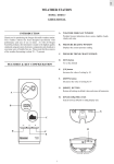
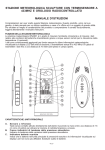
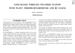
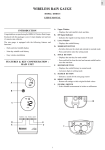
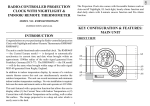
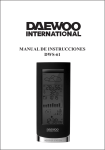
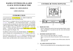
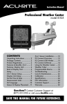
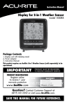
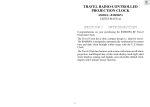
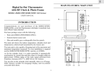
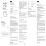
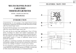
GB
WEATHER STATION
MODEL: BHB613
USER’S MANUAL
A.
INTRODUCTION
WEATHER FORECAST WINDOW
Weather forecast indication shows sunny, slightly cloudy,
cloudy and rainy.
Thank you for purchasing the Oregon Scientific weather station.
This weather station has been designed specifically with
performance and ease of use in mind. As with all Oregon
Scientific products, this barometer is made to the highest quality
standards using precision electronic components and should give
you many years of trouble free use. Please note that the accuracy
of the weather forecasting is about 70 ~ 75 percent.
B.
PRESSURE READING WINDOW
Displays the current pressure reading.
C.
PRESSURE TREND CHART WINDOW
D.
[SET] button
To set the altitude
FEATURES & KEY CONFIGURATION
E.
[UP] button
Increases the value of setting by 10
F.
[DOWN] button
Decreases the value of setting by 10
G.
[RESET] BUTTON
Returns all settings to default value and erases all memories.
A
H.
[hPa/mb-inHg] Slide switch
Selects between hPa/mb or inHg display unit.
B
G
C
D
H
F
E
1
GB
2. The weather forecasts symbols reflect forecast 12-24 hours in
the future and not the current situation..
BATTERT INSTALLATION
The unit uses four UM-4 "AAA" size batteries. If the "
"
3. A ' Sunny ' forecast reflects fine clear weather.
indicator appears, removes the exhausted batteries and follow
these steps to replace the batteries:
1. Unscrew the battery door at the bottom of the unit.
2. Remove the battery cover and insert the batteries as indicated
by the polarity symbols (+ and -) marked inside the battery
compartment.
HOW TO READ THE PRESSURE
TREND CHART
Stored memory of the barometric pressure changes are displayed
on the chart, in 5 steps indicating the pressure 1,3,6,12 and 24
hours ago. This chart is plotted by comparing the past barometric
pressure to the present pressure.
3. Replace the battery door and fasten the screw.
This gives you the pressure trend over the last 24 hours. The
weather will be getting better ( worse ) if this chart shows the bar
marks moving up ( down ) towards the present time.
AAA
AAA
AAA
AAA
Important:
It is only possible to measure the barometric pressure trend
properly if your barometer remains at the same altitude.
When moving around at different altitude within a short time
period, the air pressure changes. The barometric pressure reading
is precise only if the barometer has remained at a constant
altitude for 24 hours.
However, please note again the accuracy of a weather forecast
based on the barometric pressure reading. It is considered to
be about 70-75%.
battery
door
Note: After replacing the batteries, the whole display
will be turned on for about 3 seconds and then
show the following:
HOW TO SET THE ALTITUDE
a. Weather forecast shows slightly cloudy (a sun with the cloud
indicator )
1. Press and hold the [ SET ] button for 2 seconds to set the
altitude. The 'ALT ' indicator will turn on with the altitude
setting flashing (display in meter). The accuracy of a general
pressure-based weather forecast is about 70% to 75%.
b. Pressure trend shows steady.
c. Barometric pressure shows the current reading.
The unit takes about 24 hours to store the barometric pressure
date. Until that time has elapsed, the pressure trend and
weather forecast symbols may not reflect actual weather
forecast for your area.
Increase/decrease the altitude in steps of 10 meter by pressing
[
] or [
] button.
2. Press the [ SET ] button again to set the altitude. At this time
the previous pressure display will reappear. If the altitude
has been changed, the ' ALT ' indicator flashing (about 15
minutes ) until a new sampling takes place and the pressure
reading is then compensated with the new altitude.
HOW TO READ THE ILLUSTRATED
WEATHER FORECAST SYMBOLS
3. Press the [ SET ] button 6 times to confirm the setting you
just entered or wait for one minute for automatic exit.
Your weather station detects barometric pressure changes and
the LCD displays the illustsrated weather symbols which indicating
the weather forecast for 12 or 24 hours ahead, for an area with a
radius of about 18-30 miles.
Note: For monitoring the local barometric pressure reading,
the user needs to select the 0 meter ( preset value ) for the
altitude setting.
For monitoring the Sea Level barometric pressure reading
at certain altitude, the user needs to select the local altitude
(-100 to 2500 meters i.e. -328 to 8223 feet) for the altitude
setting. The BHB-613 requires entry of elevation in meters
not feet. Therefore, to convert feet to meters, multiply feet
by 0.3048.
Indicator
displays on
the unit
Forecas
Sunny
Slightly Cloudy
Cloudy
Rainy
Important:
To determine your location elevation, please either contact
your local library, TV/ radio weather forecaster, or via
Intenet at www.worldatlas.com/aatals/infopage/
elevation.htm.
1. The accuracy of weather forecasting when using pressure
trend alone is about 70 to 75 percent and, therefore, we
cannot be held responsible for any inconveniences caused by
an inaccurate weather forecast.
2
GB
Connector:
HOW TO SELECT THE BAR OR LINE
CHART FOR THE PRESSURE TREND
-
To get the line chart display, press the [RESET] button at the
bottom of the unit while pressing and holding the [SET] key
in the bar chart display.
-
To get the bar chart display, press the [RESET] button once.
Use wall-mount connector to align with other wall-mount bracket
if necessary.
Note: Either action will reset the unit and the previous readings/
setting will be lost.
Wall Mount
Connector
HOW TO SELECT THE PRESSURE
UNITS OF MEASURE
Wall Mount
Bracket
The switch in the battery compartment of the weather station
selects between hPa/mb and inHg. To select hPa/mb, set the
switch to hPa/mb. To select inHg, set the switch to inHg.
CONNECTOR
Un-install the brackets:
LOW BATTERY SIGNAL INDICATION
If the voltage of the batteries becomes low, the "
" indicator
will be displayed. Replace the batteries when the "
"
indicator is displayed.
TABLE STANDING OR WALL MOUNTING
Table Standing :
Your unit comes with stand connector for connecting it to the
other modular units.
MAINTENANCE
When handled properly, this unit is engineered to give you years
of satisfactory service. Here are a few product care instructions:
1. Do not immerse the unit in water. If the unit comes in contact
with water, dry it immediately with a soft lint-free cloth.
2. Do not clean the unit with abrasive or corrosive materials.
Abrasive cleaning agents may scratch the plastic parts and
corrode the electronic circuit.
STAND
CONNECTOR
3. Do not subject the unit to excessive: force, shock, dust,
temperature, or humidity. Such treatment may result in
malfunction, a shorter electronic life span, damaged batteries,
or distorted parts.
Wall-Mounting:
4. Do not tamper with the unit’s internal components. Doing so
will terminate the unit’s warranty and may cause damage.
The unit contains no user-serviceable parts.
5. Only use new batteries as specified in this instruction manual.
Do not mix new and old batteries as the old batteries may
leak.
6. Read this instruction manual thoroughly before operating the
unit.
Wall mount
bracket
3
GB
SPECIFICATION
Pressure measuring range
:
794 to 1050 hPa/mb
( 24.45 to 31.00 inHg)
Altitude compensation for
barometric pressure reading
:
-100 to 2500 meters
(-328 to 8223 feet)
Pressure display resolution
:
1 hPa/mb (0.03inHg)
Pressure sampling cycle
Power source
:
:
15 minutes
Four pcs. UM-4 or
“AAA” size batteries
Battery life
Dimension
:
:
9 month
6.64" x 2.32" x 1.28"
( H xWxD)
Weight
:
4.80 ounces
(without battery)
CAUTION
— The content of this manual is subject to change without
further notice.
— Due to printing limitation, the displays shown in this
manual may differ from the actual display.
— The contents of this manual may not be reproduced
without the permission of the manufacturer.
CUSTOMER ASSISTANCE
Should you require assistance regarding this product and its
operation, please contact our customer care department at 800853-8883 or via email at [email protected].
WARRANTY
This product is warranted to be free of manufacturing defects for
a period of 1 year from date of retail purchase. Defective product
should be directed to the place of retail purchase for exchange.
Should this not be possible, contact our customer care department
for assistance and a return material authorization. No returns
may be made without a return authorization. Please retail your
retail receipt as you may be asked to provide a copy of it for proff
of date purchased.
This warranty does not cover product subjected to abuse, misuse,
accidental damage or tampering.
4
GB
RADIO CONTROLLED ALARM CLOCK
MODEL : BHM-612A
USER’S MANUAL
A RF SIGNAL INDICATOR
- Indicates the signal-receiving status of the unit
INTRODUCTION
Congratulations on purchasing the BHM-612A Radio Controlled
Alarm Clock.
B MAIN WINDOW
- Displays the current time with seconds or day-of-the week
A smart-looking and easy-to-operate timepiece, the BHM-612A
is designed to automatically synchronize the current time and
date with the U.S. Atomic Clock.
C SECONDARY WINDOW
- Displays the alarm time and its status or date
D [ MODE/SET ] button
- Changes between seconds and weekday display (Main
window) or between calendar and alarm clock display
(secondary window)
- Holds to activate the clock setting mode
The BHM-612A is also equipped with a daily alarm clock plus
date and multilingual weekday display.
E [ UP ] button
- Increases the value of a setting by one unit
FEATURES & KEY CONFIGURATION
F [ ZONE ] button
- Press to sequence through the 4 U.S. time-zones: Pacific,
Mountain, Central or Eastern.
G [ALARM] button
- Changes the display and operating status of the alarm
clock
A
H [RESET] button
- Returns all settings to the factory set default values
BATTERY INSTALLATION
1. Open the battery compartment by removing the screw at the
bottom of the unit.
B
2. Pull out the battery holder and insert two AAA-sized (UM-4)
batteries in accordance with the polarities shown.
3. Slide back the battery holder into the compartment and fasten
the screw.
C
4. Press RESET with a blunt stylus.
5. When the low battery indicator [
] appears on the display,
follow the above procedures to replace the unit with new
batteries.
D
E
Note The unit will automatically search for the radio signal
when batteries are first installed. When the BHM-612A is
new and just out of the box, allow up to 72 hours for the
unit to receive the US Atomic Clock signal. To facilitate
reception, place the BHM-612A on a window sill away
from other signal emitting equipment such as TVs, radios,
PCs and microwaves. Stronges signal reception is between midnight and 4AM.
G
F
H
1
GB
HOW TO ENABLE OR DISABLE AUTORECEPTION
To disable the automatic signal reception feature and cause the
BHM-612A to operate as a quartz clock, hold down [ZONE] for
three seconds.
To enable the feature again, hold down the [UP] button for three
seconds. The RF signal display will start scanning to initiate
reception automatically.
Screw
Battery
Holder
HOW TO SET THE CALENDAR CLOCK
MANUALLY
When the current time is displayed:
DISPLAY MODES
In normal display, the current time, with seconds, will be
displayed in the main window and the date will be displayed in
the secondary window.
To display the weekday in the main window, press
[ MODE / SET ] once. Press the button again to display seconds.
•
Press [ MODE / SET ] for two seconds. Hours digits will
flash.
•
Set the hour using [ UP ].
•
Press [ MODE / SET ]. Minutes digits will flash.
•
Set the minutes using [ UP ].
•
Press [ MODE / SET ].
•
Follow the same pattern to enter year, month, day and the
display language for the weekday. You can choose among E
(English), F (French) and S (Spanish).
•
Press [ MODE / SET ] to save the changes and exit.
If changes are made during the process, the seconds of the clock
will reset and start from zero. The unit will also save all changes
and return to normal display automatically after the unit has been
left idle for a minute.
To display the alarm time in the secondary window, press
[ ALARM ] once. Press [ MODE / SET ] to display the date.
ABOUT RECEPTION OF RADIO SIGNAL
HOW TO SET AND USE THE ALARM
The BHM-612A is designed to automatically synchronize its
current time and date when within range of the U.S. Atomic
Clock.
To set the alarm time:
When the unit is within range, its radio-control mechanism will
override all manual settings. The benefit of a RF controlled
clock is sustained accuracy without the need of manual adjustment.
2. Press and hold [ ALARM ] for two seconds. Hours digits
will flash.
1. Press [ ALARM] to display the alarm time.
3. Set the hours using [ UP ].
4. Press [ALARM ]. Minutes digits will flash.
SIgnal Search Mode.
5. Set the minutes using [ UP ].
6. Press [ ALARM ] to save and exit. The alarm clock will be
activated automatically during the setting procedure.
Signal Reception Mode
No Signal Received
To activate or deactivate the alarm during normal display.
Complete signal reception generally takes about 2 to 10 minutes,
depending on the strength of the radio signal. When the reception
is completed, the signal display will be stable. After that, the
periodical scanning will only take a few seconds.
•
Press [ ALARM ] to display the alarm time.
•
Press [ ALARM ] to change the status of the alarm. The
respective indicator will appear.
When the alarm goes off, the alarm sound will gradually increase
in volume and speed. The alarm will continue to sound for
approximately two minutes unless interrupted when any button
is pressed. If the alarm is not interrupted, after 2 minutes the
alarm will silence itself and reactivate after approximately eight
minutes.
For better reception of radio signals, place the clock away from
metal objects and electrical appliances to minimize interference.
2
GB
Un-install the brackets:
THE RESET BUTTON
The [RESET] button is used to clear all user selected or programmed settings and to cause the settings to return to their
factory set defalut setting. Use a blunt stylus to hold down the
button.
TABLE-STANDING OR WALL-MOUNTING
Table-Standing:
The BHM612A unit comes with a stand connector for connecting
it to other modular units in the same series.
MAINTENANCE
When handled properly, this unit is engineered to give you years
of satisfactory service. Here are a few product care instructions:
1. Do not immerse the unit in water. If the unit comes in contact
with water, dry it immediately with a soft lint-free cloth.
2. Do not clean the unit with abrasive or corrosive materials.
Abrasive cleaning agents may scratch the plastic parts and
corrode the electronic circuit.
STAND
CONNECTOR
3. Do not subject the unit to excessive: force, shock, dust,
temperature, or humidity. Such treatment may result in
malfunction, a shorter electronic life span, damaged batteries,
or distorted parts.
Wall-Mounting:
4. Do not tamper with the unit’s internal components. Doing so
will terminate the unit’s warranty and may cause damage. The
unit contains no user-serviceable parts.
5. Only use new batteries as specified in this instruction manual.
Do not mix new and old batteries as the old batteries may
leak.
6. Read this instruction manual thoroughly before operating the
unit.
SPECIFICATIONS
Wall mount
bracket
Connector:
Use wall-mount connector to align with other wall-mount bracket
if neccessary.
Operating Temperature
:
32° F to 104° F
Radio Control
:
Auto synchronizes current
time and date by Radio
signal generated from the U.S.
Atomic Clock
Calender
:
Weekday in English /French/
Spanish; Current month / day
format
Clock Time
:
12-hour format
Alarm Time Duration
:
2 minutes
SNOOZE Time Duration
:
8-9mins
Accuracy
:
+/-0.5 second/day(when
operating in quartz clock
mode)
Battery Type
:
Two (2) UM-4 or "AAA" size
Unit Dimension
:
6.64" x 2.32" x 1.28" (H xW
X D)
Unit Weight
:
5.53 oz
Wall Mount
Connector
Wall Mount
Connector
3
GB
CAUTION
— The content of this manual is subject to change without
further notice.
— Due to printing limitation, the displays shown in this
manual may differ from the actual display.
— The contents of this manual may not be reproduced
without the permission of the manufacturer.
CUSTOMER ASSISTANCE
Should you require assistance regarding this product and its
operation, please contact our customer care department at 800853-8883 or via email at [email protected].
WARRANTY
This product is warranted to be free of manufacturing defects for
a period of 1 year from date of retail purchase. Defective product
should be directed to the place of retail purchase for exchange.
Should this not be possible, contact our customer care department for assistance and a return material authorization. No
returns may be made without a return authorization. Please
retain your retail receipt as you may be asked to provide a copy
of it for proof of date purchased.
This warranty does not cover product subjected to abuse, misuse,
accidental damage or tampering.
4
GB
MULTI-CHANNEL IN-OUT CABLEFREE
THERMO-HYGROMETER
MODEL: BHGR618
USER’S MANUAL
A RF SIGNAL INDICATOR
- Indicates the signal-receiving status of the unit
INTRODUCTION
Congratulations on your purchase of the Multi-Channel In-Out
Thermometer / Hygrometer (BHGR618) with a 433MHz cablefree thermo-hygro sensor.
B Upper window
- Displays the temperature data
C Lower window
- Displays the humidity data
Enclosed with this package is one (1) main display unit and
one (1) cable-free remote thermo-hygro sensor unit.
D [ IN / REMOTE ]
- Selects between the main-unit display and a selected
remote unit
- Activates search mode
The main unit has an LCD that shows recordings for indoor
and outdoor temperatures, humidity, maximum and minimum
recordings. The unit supports up to three 433MHz remote
thermo-sensors or thermo-hygro sensors.
E [ CHANNEL ] button
- Selects among different channels
- Activates remote sensor scanning mode
No wire installation is required between the main and remote
units. As the BHGR618 operates at 433MHz, it can be used in
the U.S. and most places in Continental Europe.
F
FEATURES & KEY CONFIGURATION :
MAIN UNIT
[ MEM / CLEAR ] button
- Recalls the maximum or minimum temperature and
humidity readings
- Clears the maximum and minimum temperature and
humidity memory of remote sensor channels or the main
unit display
G [ RESET ]
- Returns all settings to default values and erases all
memories
H [ °C/°F ] slide switch
- Selects between degree Centigrade (°C) and Fahrenheit
(°F)
A
B
G
C
D
F
E
H
1
GB
Note that the effective range is vastly affected by the building
materials and where the main and remote units are
positioned. Try various set-ups for best result.
a
d
b
Though the remote units are weather resistant, they should be
placed away from direct sunlight, rain or snow.
e
c
BATTERY AND CHANNEL
INSTALLATION: REMOTE UNIT
f
The remote thermo-hygro sensor unit uses two (2) UM-4 or
“AAA” size alkaline batteries.
Follow these steps to install / replace batteries:
1. Loosen the screw on the battery door.
2. Select the channel number on the CHANNEL slide switch.
3. Select the temperature display unit on the °C/°F slide switch.
4. Insert the batteries strictly according to the polarities shown
therein.
5. Replace the battery door and secure its screws.
a
LED indicator
Flashes when the remote unit transmits a reading
b
Upper window
Displays temperature data
c
Lower window
Displays humidity data
d
[ RESET ]
Returns all settings to default values
e
°C/°F slide switch
AA
FEATURES: REMOTE
THERMO-HYGRO SENSOR
(Model BHGR 228)
AA
Replace the batteries when the low-battery indicator of the
particular channel lights up on the main unit. (Repeat the
steps described in section (“BEFORE YOU BEGIN”)
Selects between Centigrade (°C) and Fahrenheit (°F)
f
Channel slide switch
Designates the remote unit Channel 1, Channel 2 or
Channel 3
Note that once a channel is assigned to a remote unit, you
can only change it by removing the batteries or resetting
the unit.
BEFORE YOU BEGIN
BATTERY INSTALLATION: MAIN UNIT
To ensure proper functioning of the BHGR618 follow this setup
procedure.
The main unit uses two (2) UM-3 or “AA” size alkaline batteries.
For best operation:
Follow these steps to install / replace batteries:
1. Assign different channels to different remote units.
1. Remove the screw to open the battery door.
2. Insert batteries in remote units before doing so for the main
unit (see instructions for battery installation).
2. Insert the batteries strictly according to the polarities shown
therein.
3. Select the temperature display unit on the °C / °F slide switch.
3. Place the main unit as close as possible to the remote unit,
reset the main unit after installing batteries. This will ensure
easier synchronization between the transmission and reception
of signals.
4. Replace the battery door and fasten the screw. Replace the
batteries when the low-battery indicator of the indoor
temperature lights up (Repeat the steps described in section
"BEFORE YOU BEGIN")
4. Position the remote unit and main unit within effective
transmission range, which, in usual circumstances, is 65 to
100 feet.
2
GB
MAXIMUM AND MINIMUM
TEMPERATURE AND HUMIDITY
AA
AA
selected. Optionally, press and hold IN/REMOTE for 2-seconds
to enforce a search.
The maximum and minimum recorded temperature and humidity
readings will automatically be stored in the memory.
To display the maximum and minimum display memory:
1. Select the channel to be checked.
2. Press [MEM/CLEAR] once to display the maximum reading
and again the minimum reading. The respective indicators,
MAX or MIN will be displayed.
If not disposed of properly, batteries can be harmful.
Protect the environment by taking exhausted batteries
to authorized disposal stations.
To clear the memory:
•
Press and hold [MEM/CLEAR] for 2-seconds.
If you press [MEM/CLEAR] now, the maximum and minimum
reading will have the same values as the current ones until
different readings are recorded.
GETTING STARTED
NOTE ON °C AND °F
Once batteries are placed in a given remote sensor unit, it will
start transmitting information at 40-second intervals.
Also, for approximately a 3-minute duration, the main unit will
automatically search for signals once batteries are installed. Upon
The unit of temperature display is selected on the °C/°F slide
switch. Select °C for Centigrade or °F for Fahrenheit.
successful reception, the individual channel temperature reading
will be displayed on the upper window and the respective humidity
reading on the lower window. The main unit will automatically
update its readings at about 40-second intervals.
Note that the remote temperature display on the main unit
is dominated by the selection on the °C/°F slide switch of
the main unit. Whatever the display units of the remote
sensors are, they will be automatically converted to the
chosen one of the main unit.
If no signals are received, blanks “ --- ” will be displayed and the
RF signal indicator will not show.
To force a signal search:
COMFORT LEVEL INDICATORS
◊ Press and hold IN/REMOTE for 2-seconds to enforce a
3-minute search.
The comfort level indicators COM, WET or DRY will tell you if
the curent environment is comfortable, too wet or too dry.
This is useful in synchronizing the transmission and reception of
the remote and main units.
The comfort indicators will appear on the display of the main and
remote units when the following conditions are satisfied:
Repeat this step whenever you find discrepancies between the
reading shown on the main unit and that on the respective remote
unit.
Indicator
displays
on the unit
Temperature
Range
Humidity
Range
Shows that the
Current
Environment
Display of readings from a remote sensor or the main unit is a
one-step procedure. The remote sensor channel or the main unit
display is indicated under the readings.
COM
20°C to 25°C
(68°F to 77°F)
40%RH70%RH
Ideal range for
both relative
humidity and
temperature
To display indoor temperature & humidity :
WET
-5°C -+ 50°C
(23°F - 122°F)
OVER70%RH
Contains excess
moisture.
DRY
-5°C -+ 50°C
(23°F - 122°F)
Below
70%RH
Contains
inadequate
moisture
No
Indicator
Less than
20°C( 68°F) or
More than
25°C (77°F)
40%RH
to
70%RH
No comment
HOW TO CHECK REMOTE AND INDOOR
TEMPERATURES & HUMIDITIES
◊ Press IN / REMOTE until "in" is displayed under the
readings.
To display remote temperature & humidity :
◊ Press CHANNEL until the appropriate remote sensor channel
is displayed under the readings.
If no readings are received from one particular channel for more
than 15 minutes, blanks “ --- ” will be displayed until further
readings are successfully searched. Check the remote sensor to
ensure that it is secure and that the correct channel has been
3
GB
HOW TO READ
THE RF SIGNAL INDICATOR
LOW BATTERY WARNING
When it is time to replace batteries, the respective low-battery
indicator will show up when the respective channel is selected.
The battery level of the main unit will be shown on the indoor
temperature when it is running low.
The RF signal indicator shows the signal-receiving status of the
main unit. There are three possible forms:
The unit is in searching mode.
THE RESET BUTTON
Transmission data are securely
registered.
To clear user-defined setting or if the unit is operating in an
unfavorable way or malfunctioning use a blunt stylus to hold
down the RESET button. All settings will return to the factory
set defaults.
No signals.
REMOTE SENSOR SCANNING
TABLE STANDING OR WALL MOUNTING
The unit can be set to automatically scan and display readings
from the remote sensors. When the remote-sensor mode is active,
the display will show the readings from one channel for about 4second and then proceed to the next channel display.
Table-Standing :
Your unit comes with stand connector for connecting it to other
modular units.
To activate the remote-sensor scanning mode:
◊ Press and hold CHANNEL for 2-seconds.
To deactivate the remote-sensor scanning mode:
◊ Press any button.
STAND
CONNECTOR
DISCONNECTED SIGNALS
If without obvious reasons the display for a particular channel
goes blank, press[IN/REMOTE] to enforce an immediate search.
Wall-mounting:
If that fails, check:
1. The remote unit of that channel is still in place.
2. The batteries of both the remote unit and main unit. Replace
as necessary.
Note that when the temperature falls below freezing point,
the batteries of outdoor units will freeze, lowering their
voltage supply and the effective range.
Wall mount
bracket
3. The transmission is within range and path is clear of obstacles
and interference. Shorten the distance when necessary.
Connector:
TRANSMISSION COLLISION
Use wall-mount connector to align with other wall-mount bracket
if necessary.
Signals from other household devices, such as door bells, home
security systems and entry controls, may interfere with those of
this product and cause temporarily reception failure. This is
normal and does not affect the general performance of the product.
The transmission and reception of readings will resume once the
interference recedes.
Wall Mount
Connector
Wall Mount
Bracket
CONNECTOR
4
GB
Un-install the brackets:
General
RF Transmission Frequency : 433 MHz
No. of Remote unit
: Maximum of 3
RF Transmission Range
: 100 feet
Temperature compensation : 0.1° C to ( 0.2°F)
Temperature sensing cycle
: around 40 seconds
Power
MAINTENANCE
Main unit
: 2 pcs UM-3 or “AA” 1.5V
alkaline battery
Remote sensing unit
: 2 pcs UM-4 or “AAA” 1.5V
alkaline battery
When handled properly, this unit is engineered to give you years
of satisfactory service. Here are a few product care instructions:
Weight
1. Do not immerse the unit in water. If the unit comes in contact
with water, dry it immediately with a soft lint-free cloth.
2. Do not clean the unit with abrasive or corrosive materials.
Abrasive cleaning agents may scratch the plastic parts and
corrode the electronic circuit.
Main unit
: 4.47 ounces
Remote sensing unit
: 3.17 ounces
Dimensions
3. Do not subject the unit to excessive: force, shock, dust, temperature, or humidity. Such treatment may result in malfunction, a shorter electronic life span, damaged batteries, or
distorted parts.
Main unit(H xW xD)
: 6.54" x 2.28" x 1.26"
Remote sensing unit
: 6.54" x 1.57" x 1.33"
4. Do not tamper with the unit’s internal components. Doing so
will terminate the unit’s warranty and may cause damage.
The unit contains no user-serviceable parts.
5. Only use new batteries as specified in this instruction manual.
Do not mix new and old batteries as the old batteries may
leak.
NOTE ON COMPLIANCE
This device complies with Part 15 of the FCC Rules. Operation
is subject to the following two conditions: (1)This device may
not cause harmful interference, and (2) This device must accept
any interference received, including interference that may cause
undesired operations.
6. Read this instruction manual thoroughly before operating the
unit.
SPECIFICATIONS
Warning: Changes or modifications to this unit not expressly
approved by the party responsible for compliance could void the
user’s authority to operate the equipment.
Main unit
Proposed operating range : - 5.0° C to 50.0°C
( 23.0° F to 122.0°F)
Temperature resolution
: 0.1° C to ( 0.2°F)
Relative Humidity
: 25% RH to 95% RH
Operating range
FCC :
NOTE: This equipment has been tested and found to comply
with the limits for a Class B digital device, pursuant to Part 15 of
the FCC Rules. These limits are designed to provide reasonable
protection against harmful interference in a residential installation.
This equipment generates, uses and can radiate radio frequency
energy and, if not installed and used in accordance with the
instructions, may cause harmful interference to radio
communications.
Remote thermo-hygro unit
Proposed operating range : -20.0° C to 60.0°C
( -4.0° F to 140.0°F)
Temperature resolution
: 0.1° C to ( 0.2°F)
Relative Humidity
: 25% RH to 95% RH
Operating range
However, there is no guarantee that interference will not occur in
a particular installation. If this equipment does cause harmful
interference to radio or television reception, which can be
determined by turning the equipment off and on, the user is
encouraged to try to correct the interference by one or more of
the following measures:
5
GB
Reorient or relocate the receiving antenna.
Increase the separation between the equipment and receiver.
Connect the equipment into an outlet on a circuit different
from that of the receiver which the receiver is needed.
Consult the dealer of an experienced radio/TV technician for
help.
Company Name: Oregon Scientific, Inc.
Address:19861 SW 95th Place, Tualatain, Oregon 97062, USA
Telephone Number:1-800-853-8883
Name and model number of the product: Multi-Channel inout Cablefree Thermo-Hygrometer BHGR618
CAUTION
— The content of this manual is subject to change without
further notice.
— Due to printing limitation, the displays shown in this
manual may differ from the actual display.
— The contents of this manual may not be reproduced
without the permission of the manufacturer.
CUSTOMER ASSISTANCE
Should you require assistance regarding this product and its
operation, please contact our customer care department at 800853-8883 or via email at [email protected].
WARRANTY
This product is warranted to be free of manufacturing defects for
a period of 1 year from date of retail purchase. Defective product
should be directed to the place of retail purchase for exchange.
Should this not be possible, contact our customer care department
for assistance and a return material authorization. No returns
may be made without a return authorization. Please retail your
retail receipt as you may be asked to provide a copy of it for proff
of date purchased.
This warranty does not cover product subjected to abuse, misuse,
accidental damage or tampering.
6
GB
WIRELESS RAIN GAUGE
MODEL: BHR616
USER’S MANUAL
A.
INTRODUCTION
- Displays the total rainfall, clock and date.
Congratulations on purchasing the BHR616 Wireless Rain Guage.
B.
Enclosed with this package is one (1) main display unit and one
(1) remote rain collector.
Daily and total rainfall display
-
Nine-day rainfall recall history
-
Easy wireless installation
RF Signal Indicator
- Indicates the signal-receiving status of the unit
C.
Lower Window
D.
MODE/SET BUTTON
The rain gauge is equipped with the following features and
functions:
-
Upper Window
- Displays the rainfall history
- Switches between the clock and calendar in normal mode
- Press and hold to enter the setting mode
E.
SINCE BUTTON
- Displays the start day for total rainfall
- Press and hold to clear the total and current rainfall and to
reset the start date
FEATURES & KEY CONFIGURATION :
MAIN UNIT
F.
HISTORY BUTTON
- Displays the rainfall history in normal mode
- Advances digits in setting mode.
G. SEARCH BUTTON
- Initiates a search for the rain gauge sensor
H. RESET BUTTON
- Returns all settings to their original default values
A
I.
[IN/MM] SWITCH
- Select rainfall measurement in inches or millimeters
B
H
C
D
E
G
F
I
1
GB
1. Remove the screws on the Rain collector as indicated in the
diagram and insert the batteries in accordance with the
polarities shown.
RAIN COLLECTOR: FEATURES
a
b
a.
2. Remove the fiber tape from the Rain Collector assembly.
Antenna
3. Position the main unit and rain collector within effective
range of each other (up to 100 feet).
-Transmits signal to main unit
b.
Cross
- To level the rain collector
4. Place the rain collector on a level surface. Add a few drops of
water; if the water collects at the center of the cross, the
collector is level.
BATTERY INSTALLATION: MAIN UNIT
The main unit uses 2 UM-3 or AA alkaline batteries.
1. Unscrew the battery door at the bottom of the unit.
2. Remove the battery door and insert batteries in accordance
with the polarities as indicated.
3. Select the display unit by the [IN/MM] switch.
Not Level
4. Replace the battery door and fasten the screw.
Level
5. If collector is not level, rotate the metal ring(s) on the feet
of the collector to adjust and level.
AA
AA
Metal Ring
Battery
door
6. Press the [RESET]
operation.
BATTERY INSTALLATION & SETTING
UP: RAIN COLLECTOR
button on the main unit to initiate
7. Press [SINCE] to display the default start date. Press and
hold to reset the start date to current date.
The Rain Collector uses 2 UM-3 or AA alkaine batteries.
2
GB
LOW BATTERY WARNING
HOW TO READ
THE RF SIGNAL INDICATOR
There are two low-battery indicators [
]. The indicator for
the rain collection unit is shown as " [
] out", and the
indicator for the main unit is shown as [
]. Replace the
batteries immediately when the respective indicator lights up.
The RF signal indicator shows the signal-receiving status of the
main unit. There are three possible forms:
The unit is in searching mode.
Note : Every time the batteries in the main unit are changed,
it is necessary to repeat installation steps 6 through
7 prior to use.
Transmission data are securely
registered.
No signals.
SETTING THE CLOCK & CALENDAR
1. Press and hold the MODE/SET button for 2 seconds.
INTERRUPTED SIGNALS
2. Choose the 12- or 24-hour display format by pressing the
HISTORY button. Press the MODE/SET button to confirm.
The success of wireless data transmission may vary and is directly
related to the positioning of the remote rain collector and the
environmental factors of that location. Should there be difficulty
in data transmission or should the main unit display go blank,
press [ SEARCH] to initiate a search signal between the main
unit and the Rain Collector unit.
3. Press and hold the MODE/SET button again. This time the
Clock will be displayed and the Hour will be flashing.
4. Press the HISTORY button once to increase its value by one.
Press the MODE/SET button to confirm its value.
5. The Minute will then be flashing. Repeat (4) to set the
minute.
If main unit remains blank verify that:
6. The calendar will now be displayed. Press and hold the
MODE/SET button for 2 seconds. The month will be
flashing. Repeat (4) again to set the current month, day and
calen dar display format (mm:dd or dd:mm).
7. After setting all values, the clock will be displayed.
-
The remote rain collector is still in place.
-
The batteries of both the main unit and rain collector are
good. Replace if necessary.
-
The transmission is within range and path is clear of
obstacles and interference. Shorten the distance if necessary.
Then press [SEARCH] again.
8. To display the calendar, press the MODE/SET button twice.
9. To display the clock again, press the MODE/SET button
twice.
THE RESET BUTTON
To reset the main unit, press the Reset button using a blunt stylus
to hold down the button. All main unit settings will return to
their original default values.
TOTAL RAINFALL
The total rainfall is displayed on the top window of the LCD
display. Upon initial activation, the rainfall amount will be
displayed in millimeters. Use the [IN/MM] switch to select
between inches and millimeters.
TABLE STANDING OR WALL MOUNTING
Table-Standing :
Your unit comes with stand connector for connecting it to other
modular units.
To display the start date of the record, press [SINCE] once.
The date will appear on top of the LCD screen. To clear the
record, hold [SINCE] for two seconds and the current date will
be set as the start date. Note that this will also clear the total
and current rainfall.
RAINFALL HISTORY
The rainfall history is displayed on the bottom window of the
LCD display. Zero (0) indicates the record for the current day.
Records for previous days are shown with a minus (-) sign; for
example : (-1) is the record for the previous day and (-2) would
be the record for two days preceding the current day. Press the
[History] button to scan the records of each day. A total of 9
day's rainfall history can be recorded and displayed.
To clear the current day rainfall, hold [SINCE] for two
seconds. Note that this will also clear the total rainfall record
and start date of the record.
STAND
CONNECTOR
3
GB
Wall-mounting:
4. Do not tamper with the unit’s internal components. Doing so
will terminate the unit’s warranty and may cause damage. The
unit contains no user-serviceable parts.
5. Only use new batteries as specified in this instruction manual.
Do not mix new and old batteries as the old batteries may
leak.
6. Read this instruction manual thoroughly before operating the
unit.
SPECIFICATIONS
Main unit
Wall mount
bracket
Proposed Operating Range
: -5°C to +50°C
Display rainfall range (total)
: 0 – 25,400 mm
Display rainfall range
: 0 – 2,540 mm
(23.0°F to 122.0°F)
Connector:
Use wall-mount connector to align with other wall-mount bracket
if necessary.
(0 - 999.99 inch)
(history / daily)
Rainfall resolution
(0 - 99.99 inch)
: 1 mm (0.04 inch)
Remote Rain Collector
Proposed operating range
: -20° C to +60°C
( -4° F to 140°C)
Wall Mount
Connector
General
Wall Mount
Bracket
RF Transmission Frequency
: 433 MHz
RF Transmission Range
: maximum 100 feet
Transmission Cycle
: 50 sec
CONNECTOR
Power
Un-install the brackets:
Main unit
: 2 pcs UM-3 or “AA” 1.5V
alkaline battery
Rain Collector unit
: 2 pcs UM-3 or “AA” 1.5V
alkaline battery
Weight
Main unit
: 4.7 ounces
Rain Collector unit
: 8.77 ounces
Dimensions
MAINTENANCE
Main unit
: 6.54" x 2.28" x 1.26"
Rain Collector unit
: Dia 4.53" x 5.71"
When handled properly, this unit is engineered to give you years
of satisfactory service. Here are a few product care instructions:
1. Do not immerse the unit in water. If the unit comes in contact
with water, dry it immediately with a soft lint-free cloth.
NOTE ON COMPLIANCE
2. Do not clean the unit with abrasive or corrosive materials.
Abrasive cleaning agents may scratch the plastic parts and
corrode the electronic circuit.
This device complies with Part 15 of the FCC Rules. Operation
is subject to the following two conditions: (1)This device may
not cause harmful interference, and (2) This device must accept
any interference received, including interference that may cause
undesired operations.
3. Do not subject the unit to excessive: force, shock, dust,
temperature, or humidity. Such treatment may result in
malfunction, a shorter electronic life span, damaged
batteries, or distorted parts.
4
GB
Warning: Changes or modifications to this unit not expressly
approved by the party responsible for compliance could void the
user’s authority to operate the equipment.
for assistance and a return material authorization. No returns
may be made without a return authorization. Please retail your
retail receipt as you may be asked to provide a copy of it for proff
of date purchased.
FCC :
This warranty does not cover product subjected to abuse, misuse,
accidental damage or tampering.
NOTE: This equipment has been tested and found to comply
with the limits for a Class B digital device, pursuant to Part 15 of
the FCC Rules. These limits are designed to provide reasonable
protection against harmful interference in a residential installation.
This equipment generates, uses and can radiate radio frequency
energy and, if not installed and used in accordance with the
instructions, may cause harmful interference to radio
communications.
However, there is no guarantee that interference will not occur in
a particular installation. If this equipment does cause harmful
interference to radio or television reception, which can be
determined by turning the equipment off and on, the user is
encouraged to try to correct the interference by one or more of
the following measures:
Reorient or relocate the receiving antenna.
Increase the separation between the equipment and receiver.
Connect the equipment into an outlet on a circuit different
from that of the receiver which the receiver is needed.
Consult the dealer of an experienced radio/TV technician for
help.
Company Name: Oregon Scientific, Inc.
Address:19861 SW 95th Place, Tualatain, Oregon 97062, USA
Telephone Number:1-800-853-8883
Name and model number of the product: Wireless Rain Gauge
BHR616
CAUTION
— The content of this manual is subject to change without
further notice.
— Due to printing limitation, the displays shown in this
manual may differ from the actual display.
— The contents of this manual may not be reproduced
without the permission of the manufacturer.
CUSTOMER ASSISTANCE
Should you require assistance regarding this product and its
operation, please contact our customer care department at 800853-8883 or via email at [email protected].
WARRANTY
This product is warranted to be free of manufacturing defects for
a period of 1 year from date of retail purchase. Defective product
should be directed to the place of retail purchase for exchange.
Should this not be possible, contact our customer care department
5