1
5.2 External Wiring
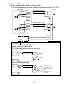
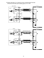
1) Wiring example of a module and an encoder
a) Wiring example with an open collector output type encoder (24 V DC)
QD62,QD62E
24 V
A20 (A13)
Shielded twisted pair cable
12 V
B20(B13)
Phase A
Encoder
OUT
+24 V
Shield
5V
A19(A12)
E
ABCOM
B19(B12)
24 V
A18(A11)
Shielded twisted pair cable
OUT
12 V
B18(B11)
Phase B
Shield
5V
A17(A10)
External
power
supply
+24 V
E
+24 V
24 V DC
0V
0V
POINT
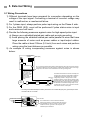
When wiring the QD62, QD62E and the encoder, separate the power
supply cable and signal cable.
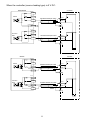
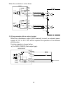
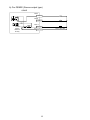
The following diagram shows an example.
[Wiring example]
OUT
QD62(E) 24 V
Phase ABCOM
A
+24 V
0V
Encoder
E
External 24 V DC
power
0V
supply
[Incorrect wiring example]
OUT
QD62(E) 24 V
Phase ABCOM
A
+24 V
0V
E
External 24 V DC
power
0V
supply
8
Encoder
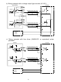
The current flows
through the shielded
twisted pair cable in
the same direction, so
there is no cancelling
effect.
This makes it more
prone to electromagnetic
induction.