1
MELSEC-L High-Speed Counter Module
User's Manual
-LD62
-LD62D
SAFETY PRECAUTIONS
(Read these precautions before using this product.)
Before using this product, please read this manual and the relevant manuals carefully and pay full attention
to safety to handle the product correctly.
The precautions given in this manual are concerned with this product only. For the safety precautions of the
programmable controller system, refer to the user's manual for the CPU module used.
In this manual, the safety precautions are classified into two levels: "
WARNING" and "
CAUTION".
WARNING
Indicates that incorrect handling may cause hazardous conditions,
resulting in death or severe injury.
CAUTION
Indicates that incorrect handling may cause hazardous conditions,
resulting in minor or moderate injury or property damage.
Under some circumstances, failure to observe the precautions given under "
CAUTION" may lead to
serious consequences.
Observe the precautions of both levels because they are important for personal and system safety.
Make sure that the end users read this manual and then keep the manual in a safe place for future
reference.
[Design Precautions]
WARNING
● In an output circuit, when a load current exceeding the rated current or an overcurrent caused by a
load short-circuit flows for a long time, it may cause smoke and fire. To prevent this, configure an
external safety circuit, such as a fuse.
● Do not write any data to the "system area" of the buffer memory in the intelligent function module.
Also, do not use any "use prohibited" signals as an input signal from the CPU module to the intelligent
function module.
Doing so may cause malfunction of the programmable controller system.
● Outputs may remain on or off due to a failure of a transistor for external output. Configure an external
circuit for monitoring output signals that could cause a serious accident.
[Design Precautions]
CAUTION
● Do not install the control lines or communication cables together with the main circuit lines or power
cables. Keep a distance of 150mm or more between them. Failure to do so may result in malfunction
due to noise.
1
[Installation Precautions]
WARNING
● Shut off the external power supply (all phases) used in the system before mounting or removing a
module. Failure to do so may result in electric shock or cause the module to fail or malfunction.
[Installation Precautions]
CAUTION
● Use the programmable controller in an environment that meets the general specifications in the Safety
Guidelines provided with the CPU module or head module. Failure to do so may result in electric
shock, fire, malfunction, or damage to or deterioration of the product.
● To interconnect modules, engage the respective connectors and securely lock the module joint levers
until they click. Incorrect interconnection may cause malfunction, failure, or drop of the module.
● Do not directly touch any conductive parts and electronic components of the module. Doing so can
cause malfunction or failure of the module.
[Wiring Precautions]
WARNING
● Shut off the external power supply (all phases) used in the system before wiring. Failure to do so may
result in electric shock or cause the module to fail or malfunction.
2
[Wiring Precautions]
CAUTION
● Individually ground the FG and LG terminals of the programmable controller with a ground resistance
of 100 or less. Failure to do so may result in electric shock or malfunction.
● Check the rated voltage and terminal layout before wiring to the module, and connect the cables
correctly. Connecting a power supply with a different voltage rating or incorrect wiring may cause a fire
or failure.
● Connectors for external devices must be crimped with the tool specified by the manufacturer or must
be correctly soldered.
Incomplete connections may cause short circuit, fire, or malfunction.
● Place the cables in a duct or clamp them. If not, dangling cable may swing or inadvertently be pulled,
resulting in damage to the module or cables or malfunction due to poor contact.
● Tighten the connector screws within the specified torque range.
Undertightening can cause drop of the screw, short circuit, fire, or malfunction.
Overtightening can damage the screw and/or module, resulting in drop, short circuit, fire, or
malfunction.
● When disconnecting the cable from the module, do not pull the cable by the cable part.
For the cable with connector, hold the connector part of the cable.
Pulling the cable connected to the module may result in malfunction or damage to the module or
cable.
● Prevent foreign matter such as dust or wire chips from entering the module. Such foreign matter can
cause a fire, failure, or malfunction.
● A protective film is attached to the top of the module to prevent foreign matter, such as wire chips,
from entering the module during wiring. Do not remove the film during wiring. Remove it for heat
dissipation before system operation.
● Ground the shield cable on the encoder side (relay box). Always ground the FG and LG terminals to
the protective ground conductor. Failure to do so may cause malfunction.
● Mitsubishi programmable controllers must be installed in control panels. Connect the main power
supply to the power supply module in the control panel through a relay terminal block. Wiring and
replacement of a power supply module must be performed by qualified maintenance personnel with
knowledge of protection against electric shock. For wiring methods, refer to the MELSEC-L CPU
Module User's Manual (Hardware Design, Maintenance and Inspection).
3
[Startup and Maintenance Precautions]
WARNING
● Do not touch any terminal while power is on. Doing so will cause electric shock or malfunction.
● Shut off the external power supply (all phases) used in the system before cleaning the module or
retightening the connector screws. Failure to do so may result in electric shock.
[Startup and Maintenance Precautions]
CAUTION
● Do not disassemble or modify the module. Doing so may cause failure, malfunction, injury, or a fire.
● Shut off the external power supply (all phases) used in the system before mounting or removing a
module. Failure to do so may cause the module to fail or malfunction.
● After the first use of the product (module and display unit), do not connect/disconnect the product
more than 50 times (in accordance with IEC 61131-2). Exceeding the limit may cause malfunction.
● Tighten the connector screws within the specified torque range. Undertightening can cause drop of
the component or wire, short circuit, or malfunction. Overtightening can damage the screw and/or
module, resulting in drop, short circuit, or malfunction.
● Before handling the module, touch a conducting object such as a grounded metal to discharge the
static electricity from the human body. Failure to do so may cause the module to fail or malfunction.
[Disposal Precautions]
CAUTION
● When disposing of this product, treat it as industrial waste.
4
CONDITIONS OF USE FOR THE PRODUCT
(1) Mitsubishi programmable controller ("the PRODUCT") shall be used in conditions;
i) where any problem, fault or failure occurring in the PRODUCT, if any, shall not lead to any major or serious accident;
and
ii) where the backup and fail-safe function are systematically or automatically provided outside of the PRODUCT for the
case of any problem, fault or failure occurring in the PRODUCT.
(2) The PRODUCT has been designed and manufactured for the purpose of being used in general industries.
MITSUBISHI SHALL HAVE NO RESPONSIBILITY OR LIABILITY (INCLUDING, BUT NOT LIMITED TO ANY AND ALL
RESPONSIBILITY OR LIABILITY BASED ON CONTRACT, WARRANTY, TORT, PRODUCT LIABILITY) FOR ANY
INJURY OR DEATH TO PERSONS OR LOSS OR DAMAGE TO PROPERTY CAUSED BY the PRODUCT THAT ARE
OPERATED OR USED IN APPLICATION NOT INTENDED OR EXCLUDED BY INSTRUCTIONS, PRECAUTIONS, OR
WARNING CONTAINED IN MITSUBISHI'S USER, INSTRUCTION AND/OR SAFETY MANUALS, TECHNICAL
BULLETINS AND GUIDELINES FOR the PRODUCT.
("Prohibited Application")
Prohibited Applications include, but not limited to, the use of the PRODUCT in;
• Nuclear Power Plants and any other power plants operated by Power companies, and/or any other cases in which the
public could be affected if any problem or fault occurs in the PRODUCT.
• Railway companies or Public service purposes, and/or any other cases in which establishment of a special quality
assurance system is required by the Purchaser or End User.
• Aircraft or Aerospace, Medical applications, Train equipment, transport equipment such as Elevator and Escalator,
Incineration and Fuel devices, Vehicles, Manned transportation, Equipment for Recreation and Amusement, and
Safety devices, handling of Nuclear or Hazardous Materials or Chemicals, Mining and Drilling, and/or other
applications where there is a significant risk of injury to the public or property.
Notwithstanding the above, restrictions Mitsubishi may in its sole discretion, authorize use of the PRODUCT in one or
more of the Prohibited Applications, provided that the usage of the PRODUCT is limited only for the specific
applications agreed to by Mitsubishi and provided further that no special quality assurance or fail-safe, redundant or
other safety features which exceed the general specifications of the PRODUCTs are required. For details, please
contact the Mitsubishi representative in your region.
5
INTRODUCTION
Thank you for purchasing the Mitsubishi MELSEC-L series programmable controllers.
This manual describes the functions and programming of a high-speed counter module.
Before using this product, please read this manual and the relevant manuals carefully and develop familiarity with the
functions and performance of the MELSEC-L series programmable controller to handle the product correctly.
When applying the program examples introduced in this manual to an actual system, ensure the applicability and
confirm that it will not cause system control problems.
Relevant modules: LD62, LD62D
Remark
Unless otherwise specified, this manual describes the program examples in which the I/O numbers of X/Y00 to X/Y0F are
assigned for a high-speed counter module.
For I/O number assignment, refer to the following.
MELSEC-L CPU Module User's Manual (Function Explanation, Program Fundamentals)
Operating procedures are explained using GX Works2. When using GX Developer or GX Configurator-CT, refer to the
following.
• When using GX Developer or GX Configurator-CT (
6
Page 120, Appendix 5)
COMPLIANCE WITH EMC AND LOW VOLTAGE
DIRECTIVES
(1) Method of ensuring compliance
To ensure that Mitsubishi programmable controllers maintain EMC and Low Voltage Directives when incorporated
into other machinery or equipment, certain measures may be necessary. Please refer to one of the following
manuals.
• MELSEC-L CPU Module User's Manual (Hardware Design, Maintenance and Inspection)
• MELSEC-L CC-Link IE Field Network Head Module User's Manual
• Safety Guidelines (This manual is included with the CPU module or head module.)
The CE mark on the side of the programmable controller indicates compliance with EMC and Low Voltage
Directives.
(2) Additional measures
To ensure that this product maintains EMC and Low Voltage Directives, please refer to Page 37, Section 6.2.1
(4).
7
RELEVANT MANUALS
(1) CPU module user's manual
Manual name
Description
<manual number (model code)>
MELSEC-L CPU Module User's Manual (Hardware Design,
Specifications of the CPU modules, power supply modules, display
Maintenance and Inspection)
unit, branch module, extension module, SD memory cards, and
batteries, information on how to establish a system, maintenance
<SH-080890ENG, 13JZ36>
and inspection, and troubleshooting
MELSEC-L CPU Module User's Manual (Function Explanation,
Program Fundamentals)
Functions and devices of the CPU module, and programming
<SH-080889ENG, 13JZ35>
(2) Head module user's manual
Manual name
Description
<manual number (model code)>
MELSEC-L CC-Link IE Field Network Head Module User's Manual
<SH-080919ENG, 13JZ48>
Specifications, procedures before operation, system configuration,
installation, wiring, settings, and troubleshooting of the head module
(3) Operating manual
Manual name
Description
<manual number (model code)>
GX Works2 Version 1 Operating Manual (Common)
<SH-080779ENG, 13JU63>
GX Developer Version 8 Operating Manual
GX Works2, which are common to Simple projects and Structured
projects
Operating methods of GX Developer, such as programming,
<SH-080373E, 13JU41>
8
System configuration, parameter settings, and online operations of
printing, monitoring, and debugging
Memo
9
CONTENTS
CONTENTS
SAFETY PRECAUTIONS . . . . . . . . . . . . . . . . . . . . . . . . . . . . . . . . . . . . . . . . . . . . . . . . . . . . . . . . . . . . . 1
CONDITIONS OF USE FOR THE PRODUCT . . . . . . . . . . . . . . . . . . . . . . . . . . . . . . . . . . . . . . . . . . . . . 5
INTRODUCTION . . . . . . . . . . . . . . . . . . . . . . . . . . . . . . . . . . . . . . . . . . . . . . . . . . . . . . . . . . . . . . . . . . . . 6
COMPLIANCE WITH EMC AND LOW VOLTAGE DIRECTIVES . . . . . . . . . . . . . . . . . . . . . . . . . . . . . . . 7
RELEVANT MANUALS . . . . . . . . . . . . . . . . . . . . . . . . . . . . . . . . . . . . . . . . . . . . . . . . . . . . . . . . . . . . . . . 8
MANUAL PAGE ORGANIZATION . . . . . . . . . . . . . . . . . . . . . . . . . . . . . . . . . . . . . . . . . . . . . . . . . . . . . . 13
TERMS . . . . . . . . . . . . . . . . . . . . . . . . . . . . . . . . . . . . . . . . . . . . . . . . . . . . . . . . . . . . . . . . . . . . . . . . . . 14
PACKING LIST . . . . . . . . . . . . . . . . . . . . . . . . . . . . . . . . . . . . . . . . . . . . . . . . . . . . . . . . . . . . . . . . . . . . 14
CHAPTER 1 HIGH-SPEED COUNTER MODULE
1.1
Application . . . . . . . . . . . . . . . . . . . . . . . . . . . . . . . . . . . . . . . . . . . . . . . . . . . . . . . . . . . . . . . . 15
1.2
Features . . . . . . . . . . . . . . . . . . . . . . . . . . . . . . . . . . . . . . . . . . . . . . . . . . . . . . . . . . . . . . . . . . 16
CHAPTER 2 PART NAMES
18
CHAPTER 3 SPECIFICATIONS
20
3.1
3.2
General Specifications . . . . . . . . . . . . . . . . . . . . . . . . . . . . . . . . . . . . . . . . . . . . . . . . . . . . . . . 20
Performance Specifications . . . . . . . . . . . . . . . . . . . . . . . . . . . . . . . . . . . . . . . . . . . . . . . . . . . 21
3.2.1
Number of parameters that can be set. . . . . . . . . . . . . . . . . . . . . . . . . . . . . . . . . . . . . . . . . . .23
3.3
Function List . . . . . . . . . . . . . . . . . . . . . . . . . . . . . . . . . . . . . . . . . . . . . . . . . . . . . . . . . . . . . . . 25
3.4
List of I/O Signals . . . . . . . . . . . . . . . . . . . . . . . . . . . . . . . . . . . . . . . . . . . . . . . . . . . . . . . . . . . 26
3.5
List of Buffer Memory Areas . . . . . . . . . . . . . . . . . . . . . . . . . . . . . . . . . . . . . . . . . . . . . . . . . . . 27
CHAPTER 4 PROCEDURES BEFORE OPERATION
29
CHAPTER 5 SYSTEM CONFIGURATION
31
5.1
5.2
Overall Configuration . . . . . . . . . . . . . . . . . . . . . . . . . . . . . . . . . . . . . . . . . . . . . . . . . . . . . . . . 31
Applicable System . . . . . . . . . . . . . . . . . . . . . . . . . . . . . . . . . . . . . . . . . . . . . . . . . . . . . . . . . . 33
5.2.1
Restrictions when the high-speed counter module is connected to the head module . . . . . . .33
CHAPTER 6 INSTALLATION AND WIRING
34
6.1
Installation Environment and Installation Position . . . . . . . . . . . . . . . . . . . . . . . . . . . . . . . . . . 34
6.2
Wiring . . . . . . . . . . . . . . . . . . . . . . . . . . . . . . . . . . . . . . . . . . . . . . . . . . . . . . . . . . . . . . . . . . . . 35
6.2.1
Wiring precautions . . . . . . . . . . . . . . . . . . . . . . . . . . . . . . . . . . . . . . . . . . . . . . . . . . . . . . . . . .35
6.2.2
Connectors for external devices. . . . . . . . . . . . . . . . . . . . . . . . . . . . . . . . . . . . . . . . . . . . . . . .39
6.2.3
Interface with external devices. . . . . . . . . . . . . . . . . . . . . . . . . . . . . . . . . . . . . . . . . . . . . . . . .41
6.2.4
Connectable encoders . . . . . . . . . . . . . . . . . . . . . . . . . . . . . . . . . . . . . . . . . . . . . . . . . . . . . . .46
6.3
Examples of Wiring Between the High-Speed Counter Module and an Encoder . . . . . . . . . . . 47
6.4
Examples of Wiring Between a Controller and External Input Terminals . . . . . . . . . . . . . . . . . 49
6.5
Examples of Wiring with External Output Terminals . . . . . . . . . . . . . . . . . . . . . . . . . . . . . . . . . 52
CHAPTER 7 SETTINGS
10
15
53
7.1
Adding a Module. . . . . . . . . . . . . . . . . . . . . . . . . . . . . . . . . . . . . . . . . . . . . . . . . . . . . . . . . . . . 53
7.2
Switch Setting . . . . . . . . . . . . . . . . . . . . . . . . . . . . . . . . . . . . . . . . . . . . . . . . . . . . . . . . . . . . . . 54
7.3
Intelligent Function Module Detailed Setting . . . . . . . . . . . . . . . . . . . . . . . . . . . . . . . . . . . . . . 55
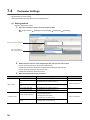
7.4
Parameter Settings . . . . . . . . . . . . . . . . . . . . . . . . . . . . . . . . . . . . . . . . . . . . . . . . . . . . . . . . . . 56
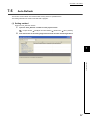
7.5
Auto Refresh. . . . . . . . . . . . . . . . . . . . . . . . . . . . . . . . . . . . . . . . . . . . . . . . . . . . . . . . . . . . . . . 57
CHAPTER 8 FUNCTIONS
8.1
8.2
58
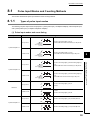
Pulse Input Modes and Counting Methods. . . . . . . . . . . . . . . . . . . . . . . . . . . . . . . . . . . . . . . . 59
8.1.1
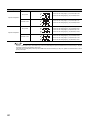
Types of pulse input modes . . . . . . . . . . . . . . . . . . . . . . . . . . . . . . . . . . . . . . . . . . . . . . . . . . .59
8.1.2
Setting a counting method . . . . . . . . . . . . . . . . . . . . . . . . . . . . . . . . . . . . . . . . . . . . . . . . . . . .62
8.1.3
Reading the present value . . . . . . . . . . . . . . . . . . . . . . . . . . . . . . . . . . . . . . . . . . . . . . . . . . . .62
Selecting Counter Type . . . . . . . . . . . . . . . . . . . . . . . . . . . . . . . . . . . . . . . . . . . . . . . . . . . . . . 63
8.2.1
Linear counter function. . . . . . . . . . . . . . . . . . . . . . . . . . . . . . . . . . . . . . . . . . . . . . . . . . . . . . .64
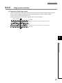
8.2.2
Ring counter function . . . . . . . . . . . . . . . . . . . . . . . . . . . . . . . . . . . . . . . . . . . . . . . . . . . . . . . .65
8.3
Coincidence Output Function . . . . . . . . . . . . . . . . . . . . . . . . . . . . . . . . . . . . . . . . . . . . . . . . . . 68
8.4
Preset Function. . . . . . . . . . . . . . . . . . . . . . . . . . . . . . . . . . . . . . . . . . . . . . . . . . . . . . . . . . . . . 73
8.5
Counter Function Selection . . . . . . . . . . . . . . . . . . . . . . . . . . . . . . . . . . . . . . . . . . . . . . . . . . . 75
8.5.1
Reading the counter function selection count value. . . . . . . . . . . . . . . . . . . . . . . . . . . . . . . . .76
8.5.2
Count error . . . . . . . . . . . . . . . . . . . . . . . . . . . . . . . . . . . . . . . . . . . . . . . . . . . . . . . . . . . . . . . .77
8.6
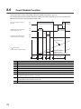
Count Disable Function . . . . . . . . . . . . . . . . . . . . . . . . . . . . . . . . . . . . . . . . . . . . . . . . . . . . . . 78
8.7
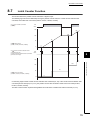
Latch Counter Function . . . . . . . . . . . . . . . . . . . . . . . . . . . . . . . . . . . . . . . . . . . . . . . . . . . . . . 79
8.8
Sampling Counter Function . . . . . . . . . . . . . . . . . . . . . . . . . . . . . . . . . . . . . . . . . . . . . . . . . . . 80
8.9
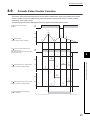
Periodic Pulse Counter Function . . . . . . . . . . . . . . . . . . . . . . . . . . . . . . . . . . . . . . . . . . . . . . . 81
CHAPTER 9 DISPLAY UNIT
83
9.1
Features . . . . . . . . . . . . . . . . . . . . . . . . . . . . . . . . . . . . . . . . . . . . . . . . . . . . . . . . . . . . . . . . . . 83
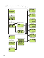
9.2
Menu Transition . . . . . . . . . . . . . . . . . . . . . . . . . . . . . . . . . . . . . . . . . . . . . . . . . . . . . . . . . . . . 83
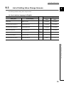
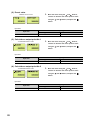
9.3
List of Setting Value Change Screens . . . . . . . . . . . . . . . . . . . . . . . . . . . . . . . . . . . . . . . . . . . 85
CHAPTER 10 PROGRAMMING
88
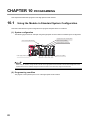
10.1
Using the Module in Standard System Configuration . . . . . . . . . . . . . . . . . . . . . . . . . . . . . . . . 88
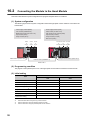
10.2
Connecting the Module to the Head Module . . . . . . . . . . . . . . . . . . . . . . . . . . . . . . . . . . . . . . 96
10.3
Program Example with the Coincidence Detection Interrupt Function . . . . . . . . . . . . . . . . . . 106
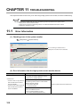
CHAPTER 11 TROUBLESHOOTING
108
11.1
Error Information. . . . . . . . . . . . . . . . . . . . . . . . . . . . . . . . . . . . . . . . . . . . . . . . . . . . . . . . . . . 108
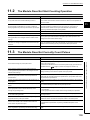
11.2
The Module Does Not Start Counting Operation . . . . . . . . . . . . . . . . . . . . . . . . . . . . . . . . . . 109
11.3
The Module Does Not Correctly Count Pulses . . . . . . . . . . . . . . . . . . . . . . . . . . . . . . . . . . . . 109
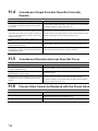
11.4
Coincidence Output Function Does Not Correctly Operate . . . . . . . . . . . . . . . . . . . . . . . . . . 110
11.5
Coincidence Detection Interrupt Does Not Occur. . . . . . . . . . . . . . . . . . . . . . . . . . . . . . . . . . 110
11.6
Present Value Cannot be Replaced with the Preset Value . . . . . . . . . . . . . . . . . . . . . . . . . . . 110
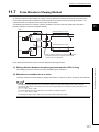
11.7
Pulse Waveform Shaping Method . . . . . . . . . . . . . . . . . . . . . . . . . . . . . . . . . . . . . . . . . . . . . 111
APPENDICES
112
Appendix 1 Details of I/O Signals. . . . . . . . . . . . . . . . . . . . . . . . . . . . . . . . . . . . . . . . . . . . . . . . . . . 112
11
Appendix 1.1
Input signals . . . . . . . . . . . . . . . . . . . . . . . . . . . . . . . . . . . . . . . . . . . . . . . . . . . . . . . . 112
Appendix 1.2
Output signals . . . . . . . . . . . . . . . . . . . . . . . . . . . . . . . . . . . . . . . . . . . . . . . . . . . . . . 114
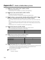
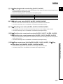
Appendix 2 Details of Buffer Memory Areas . . . . . . . . . . . . . . . . . . . . . . . . . . . . . . . . . . . . . . . . . . 116
Appendix 3 Checking Serial Number and Function Version . . . . . . . . . . . . . . . . . . . . . . . . . . . . . . 118
Appendix 4 Differences Between L Series and Q Series Modules . . . . . . . . . . . . . . . . . . . . . . . . . 119
Appendix 5 When Using GX Developer and GX Configurator-CT . . . . . . . . . . . . . . . . . . . . . . . . . . 120
Appendix 5.1
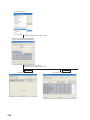
GX Developer operation . . . . . . . . . . . . . . . . . . . . . . . . . . . . . . . . . . . . . . . . . . . . . .120
Appendix 5.2
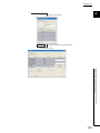
GX Configurator-CT operation . . . . . . . . . . . . . . . . . . . . . . . . . . . . . . . . . . . . . . . . . .123
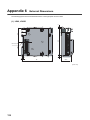
Appendix 6 External Dimensions . . . . . . . . . . . . . . . . . . . . . . . . . . . . . . . . . . . . . . . . . . . . . . . . . . . 126
INDEX
128
REVISIONS . . . . . . . . . . . . . . . . . . . . . . . . . . . . . . . . . . . . . . . . . . . . . . . . . . . . . . . . . . . . . . . . . . . . . . 130
WARRANTY . . . . . . . . . . . . . . . . . . . . . . . . . . . . . . . . . . . . . . . . . . . . . . . . . . . . . . . . . . . . . . . . . . . . . 131
TRADEMARKS . . . . . . . . . . . . . . . . . . . . . . . . . . . . . . . . . . . . . . . . . . . . . . . . . . . . . . . . . . . . . . . . . . . 132
12
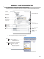
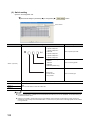
MANUAL PAGE ORGANIZATION
In this manual, pages are organized and the symbols are used as shown below.
The following illustration is for explanation purpose only, and should not be referred to as an actual documentation.
"" is used for
screen names and items.
The chapter of
the current page is shown.
shows operating
procedures.
shows mouse
operations.*1
[ ] is used for items
in the menu bar and
the project window.
The section of
the current page is shown.
Ex. shows setting or
operating examples.
shows reference
manuals.
shows notes that
requires attention.
shows
reference pages.
shows useful
information.
*1
The mouse operation example (for GX Works2) is provided below.
Menu bar
Ex.
[Online]
[Write to PLC...]
Select [Online] on the menu bar,
and then select [Write to PLC...].
A window selected in the view selection area is displayed.
Ex.
[Parameter]
Project window
[PLC Parameter]
Select [Project] from the view selection
area to open the Project window.
In the Project window, expand [Parameter] and
select [PLC Parameter].
View selection area
13
TERMS
Unless otherwise specified, this manual uses the following terms.
Term
Description
High-speed counter module
Another term for the MELSEC-L series high-speed counter module
Head module
Abbreviation for the LJ72GF15-T2 CC-Link IE Field Network head module
Display unit
A liquid crystal display to be attached to the CPU module
Programming tool
Generic term for GX Works2 and GX Developer
GX Works2
GX Developer
GX Configurator-CT
Buffer memory
The product name of the software package for the MELSEC programmable controllers
A setting and monitoring tool added in GX Developer (for high-speed counter modules)
A memory in an intelligent function module, where data (such as setting values and monitoring values)
exchanged with a CPU module are stored
PACKING LIST
The following items are included in the package of this product. Before use, check that all the items are included.
High-speed counter module
Module
14
Before Using the Product
CHAPTER 1 HIGH-SPEED COUNTER MODULE
CHAPTER 1
HIGH-SPEED COUNTER MODULE
1
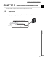
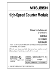
This chapter describes the application and the features of the high-speed counter module.
1.1
Application
The high-speed counter module is capable of counting the number of inputs of a high-speed pulse that cannot be
measured by a sequence using general-purpose input modules.
Temporarily stops the inverter. (Coincidence output)
Encoder (pulse generator)
CH2
Encoder
(pulse generator)
CH1
1.1 Application
15
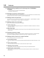
1.2
Features
(1) Offering counting capability over the wide range from -2147483648 to
2147483647
• The module stores a count value in 32-bit signed binary.
• The number of channels is two.
(2) Switching the maximum counting speed
For the LD62D, 500k/200k/100k/10k can be switched and for the LD62, 200k/100k/10k can be switched, thereby
achieving an error-free count even if a pulse has a gradual rising/falling edge.
(3) Allowing selection of pulse input
The pulse input mode can be selected from the following: 1-phase multiple of 1, 1-phase multiple of 2, 2-phase
multiple of 1, 2-phase multiple of 2, 2-phase multiple of 4, and CW/CCW.
(4) Allowing selection of counter types
Either one of the following counter types can be selected.
(a) Linear counter type
This type is capable of counting pulses ranging from -2147483648 to 2147483647 and detects an overflow if
this range is exceeded.
(b) Ring counter type
This type counts pulses repeatedly under the range of the ring counter upper limit value and the ring counter
lower limit value.
(5) Permitting coincidence output
Outputting on/off signals or initiating an interrupt program is possible at the timing when a coincidence output
point, which is set arbitrarily beforehand, matches the current value in comparison with each other.
(6) Allowing selection from the four counter functions
One of the following functions can be selected for use.
(a) Count disable function
This function makes the pulse count stop by inputting a signal while CH Count enable command (Y4, YC) is
on.
(b) Latch counter function
This function latches the current value of a counter at the time of input of a signal.
(c) Sampling counter function
Of input signals, this function counts pulses that are input during a time specified beforehand.
(d) Periodic pulse counter function
While signals are input, this function stores the current value and previous value of a counter at each prespecified period.
16
CHAPTER 1 HIGH-SPEED COUNTER MODULE
(7) Executing the preset function and the counter function selection via external
control signals
1
• Applying a voltage to the preset input terminal allows the preset function to be performed.
• Applying a voltage to the function start input terminal allows the counter function selection to be performed.
(8) Easy settings with GX Works2
GX Works2 allows Initial settings and auto refresh settings to be configured on the window, resulting in the
reduction of programs and making it easier to check the status of module settings and operation.
1.2 Features
17
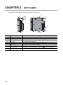
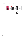
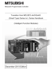
CHAPTER 2
PART NAMES
The following table lists the part names of the high-speed counter module.
1)
1)
2)
3)
4)
5)
7)
6)
1)
No.
1)
Name
Description
1)
Module joint levers
Levers for connecting two modules
2)
A LED
On: A voltage is being applied to the phase A pulse input terminal.
3)
B LED
On: A voltage is being applied to the phase B pulse input terminal.
4)
DEC. LED
On: Pulses are being counted down.
5)
FUNC. LED
On: A voltage is being applied to the function start input terminal.
6)
DIN rail hook
A hook used to mount the module to a DIN rail
7)
8)
18
8)
Connector for external
devices (40 pins)
Serial number display
A connector for I/O signal cables of external devices (
Displays the serial number printed on the rating plate.
Page 41, Section 6.2.3)
CHAPTER 2 PART NAMES
Memo
2
19
CHAPTER 3
SPECIFICATIONS
This chapter describes general specifications, performance specifications, functions, I/O signals, and buffer memory
areas.
3.1
General Specifications
For the general specifications of the high-speed counter module, refer to the following.
Safety Guidelines, provided with the CPU module or head module
20
CHAPTER 3 SPECIFICATIONS
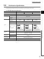
3.2
Performance Specifications
The following table describes the performance specifications of the high-speed counter module.
(1) LD62 (DC input sink output type)
Item
Counting speed switch setting*1
Specifications
200k (100k to 200kPPS)
Number of occupied I/O points
100k (10k to 100kPPS)
16 points (I/O assignment: Intelligent, 16 points)
Number of channels
2 channels
Phase
Count input signal
3
10k (10kPPS or less)
1-phase input (1 multiple/2 multiples), 2-phase input (1 multiple/2 multiples/4 multiples),
CW/CCW input
Signal level
5/12/24VDC 2 to 5mA
(A, B)
Counting speed
200kPPS
(maximum)*2
100kPPS
10kPPS
Counting range
32-bit signed binary (-2147483648 to 2147483647)
Type
UP/DOWN preset counter + Ring counter functions
5
Counter
10
100
Minimum count pulse
width
(duty ratio 50%)
output
(Unit : s)
5
5
(Unit : s)
50 50
(Unit : s)
(Minimum phase difference
(Minimum phase difference
(Minimum phase difference
in 2-phase input 1.25s)
in 2-phase input 2.5s)
in 2-phase input 25s)
32-bit signed binary
Setting value < Count value
Comparison result
Setting value = Count value
Setting value > Count value
External input
External output
Preset
Function start
Coincidence output
5/12/24VDC
2 to 5mA
Transistor (sink type) output, 2 points/channel
12/24VDC 0.5A/point, 2A/common
Internal current consumption (5VDC)
0.31A
Weight
0.13kg
21
3.2 Performance Specifications
Comparison range
Coincidence
2.5 2.5
*1
*2
The value can be configured in intelligent function module switch setting.
The counting speed is affected by the pulse rise/fall time.
The number of pulses that can be counted depending on the counting speed is as follows. Note that the count may be
incorrect when pulses with long rise/fall time are counted.
Counting speed switch
setting
200k
100k
Rise/fall time
10k
Both 1- and 2-phase inputs
t = 1.25s or less
200kPPS
100kPPS
10kPPS
t = 2.5s or less
100kPPS
100kPPS
10kPPS
t = 25s or less
10kPPS
10kPPS
t = 500s
500PPS
t
t
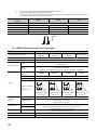
(2) LD62D (differential input sink output type)
Item
Counting speed switch setting*1
Specifications
500k (200k to
200k (100k to
100k (10k to
500kPPS)
200kPPS)
100kPPS)
Number of occupied I/O points
16 points (I/O assignment: Intelligent, 16 points)
Number of channels
2 channels
Phase
Count input signal
10k (10kPPS or less)
1-phase input (1 multiple/2 multiples), 2-phase input (1 multiple/2 multiples/4 multiples),
CW/CCW input
EIA Standard RS-422-A
Signal level
Differential line driver level
(A, B)
(AM26LS31 (manufactured by Texas Instruments Incorporated) or equivalent)
Counting speed
500kPPS
(maximum)*2
200kPPS
100kPPS
10kPPS
Counting range
32-bit signed binary (-2147483648 to 2147483647)
Type
UP/DOWN preset counter + Ring counter functions
5
2
Counter
100
10
Minimum count pulse
width
(duty ratio 50%)
Comparison range
Coincidence
output
1
1
(Unit : s)
2.5 2.5
5
(Unit : s)
5
(Unit : s)
50 50
(Minimum phase
(Minimum phase
(Minimum phase
(Minimum phase
difference in 2-phase
difference in 2-phase
difference in 2-phase
difference in 2-phase
input 0.5s)
input 1.25s)
input 2.5s)
input 25s)
32-bit signed binary
Setting value < Count value
Comparison result
Setting value = Count value
Setting value > Count value
External input
External output
Preset
Function start
Coincidence output
5/12/24VDC 2 to 5mA
(EIA Standard RS-422-A differential line driver can be connected.)
Transistor (sink type) output, 2 points/channel
12/24VDC 0.5A/point, 2A/common
Internal current consumption (5VDC)
0.36A
Weight
0.13kg
22
(Unit : s)
CHAPTER 3 SPECIFICATIONS
*1
*2
The value can be configured in intelligent function module switch setting.
The counting speed is affected by the pulse rise/fall time.
The number of pulses that can be counted depending on the counting speed is as follows. Note that the count may be
incorrect when pulses with long rise/fall time are counted.
Counting speed switch
500k
setting
200k
Rise/fall time
100k
10k
Both 1- and 2-phase inputs
t = 0.5s or less
500kPPS
200kPPS
100kPPS
10kPPS
t = 1.25s or less
200kPPS
200kPPS
100kPPS
10kPPS
t = 2.5s or less
100kPPS
100kPPS
10kPPS
t = 25s or less
10kPPS
10kPPS
t = 500s
500PPS
t
3.2.1
3
t
Number of parameters that can be set
Configure the parameters of the initial setting and the auto refresh of the high-speed counter module within the number
of parameters that can be set to the CPU module or head module, including the number of parameters set for other
intelligent function modules. For the number of parameters that can be set to the CPU module and head module, refer
to the following.
MELSEC-L CPU Module User's Manual (Hardware Design, Maintenance and Inspection)
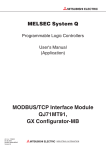
(1) Number of high-speed counter module parameters
The following number of parameters can be set for one high-speed counter module.
Model
Initial setting
Auto refresh
LD62
8
14 (maximum number of parameters)
LD62D
8
14 (maximum number of parameters)
23
3.2 Performance Specifications
3.2.1 Number of parameters that can be set
MELSEC-L CC-Link IE Field Network Head Module User's Manual
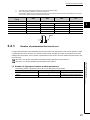
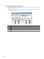
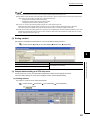
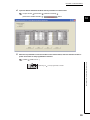
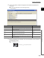
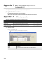
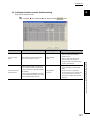
(2) Checking the number of parameters
The number of parameters set for the intelligent function module and the maximum number of parameters can be
checked by the following operation.
Project window
[Intelligent Function Module]
Right-click
[Intelligent Function Module
Parameter List]
1)
No.
24
2)
3)
4)
Description
1)
The total number of parameters that have been selected under "Initialization (Count)"
2)
The maximum number of parameters for initial setting
3)
The total number of parameters that have been selected under "Auto Refresh (Count)"
4)
The maximum number of parameters for auto refresh setting
CHAPTER 3 SPECIFICATIONS
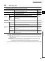
3.3
Function List
The following table lists the functions of the high-speed counter module.
Item
Description
This function counts pulses between -2147483648 and 2147483647 and detects an
Linear counter function
overflow if the count value is outside the range.
This function repeatedly counts pulses between the ring counter upper limit value
Ring counter function
and the ring counter lower limit value.
Coincidence
Coincidence
output function
detection
interrupt
function
program when the present counter value matches with the preset coincidence output
3
Section 8.2.2
Page 68,
Section 8.3
point setting value.
This function stops counting pulses while CH Count enable command (Y4, YC) is
function
on.
Counter function
selection
This function outputs an interrupt signal to the CPU module and starts an interrupt
Count disable
function
Page 65,
point setting value and outputs on or off signal when they match.
This function is performed by a program or an external control signal (preset input).
Latch counter
Page 64,
Section 8.2.1
This function compares the present counter value with the preset coincidence output
This function overwrites the present counter value with the preset value.
Preset function
Reference
This function stores the present counter value to the buffer memory when the
counter function selection start command signal is input.
This function is performed by a program or an external control signal (function input).
Page 73,
Section 8.4
Page 78,
Section 8.6
Page 79,
Section 8.7
This function counts pulses input during the specified sampling period after the
Sampling
counter function selection start command is input and stores the counter value to the
counter function
buffer memory.
Page 80,
Section 8.8
This function is performed by a program or an external control signal (function input).
Periodic pulse
buffer memory areas at the preset cycle while the counter function selection start
command signal is input.
Page 81,
Section 8.9
● These functions can be used together.
However, select either the linear counter function or the ring counter function and any one of the counter functions from
counter function selection.
● The preset function and the function selected from counter function selection can also be performed by the following
external inputs.
• To use the preset function, apply a voltage to the preset input terminal.
• To use any function of the counter function selection, apply a voltage to the function start input terminal.
25
3.3 Function List
counter function
This function stores the present and previous counter values to the corresponding
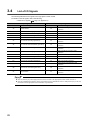
3.4
List of I/O Signals
The following table lists the I/O signals of the high-speed counter module.
For details on the I/O signals, refer to the following.
• Details of I/O signals (
Page 112, Appendix 1)
Input signal
Device No.
Signal name
Output signal
Device No.
Signal name
CH1 Coincidence signal No.1 reset
X0
Module READY
Y0
X1
CH1 Counter value large (point No.1)
Y1
CH1 Preset command
X2
CH1 Counter value coincidence (point No.1)
Y2
CH1 Coincidence signal enable command
X3
CH1 Counter value small (point No.1)
Y3
CH1 Down count command
X4
CH1 External preset request detection
Y4
CH1 Count enable command
X5
CH1 Counter value large (point No.2)
Y5
command
CH1 External preset detection reset
command
CH1 Counter function selection start
X6
CH1 Counter value coincidence (point No.2)
Y6
X7
CH1 Counter value small (point No.2)
Y7
X8
CH2 Counter value large (point No.1)
Y8
X9
CH2 Counter value coincidence (point No.1)
Y9
CH2 Preset command
command
CH1 Coincidence signal No.2 reset
command
CH2 Coincidence signal No.1 reset
command
XA
CH2 Counter value small (point No.1)
YA
CH2 Coincidence signal enable command
XB
CH2 External preset request detection
YB
CH2 Down count command
XC
CH2 Counter value large (point No.2)
YC
CH2 Count enable command
XD
CH2 Counter value coincidence (point No.2)
YD
XE
CH2 Counter value small (point No.2)
YE
XF
Use prohibited
YF
CH2 External preset detection reset
command
CH2 Counter function selection start
command
CH2 Coincidence signal No.2 reset
command
● The I/O numbers (X/Y) above apply when the start I/O number of the high-speed counter module is set to "0".
● The use prohibited signal above is used by the system and is not available for users. If used (turned on) by a user, the
performance of the high-speed counter module is not guaranteed.
26
CHAPTER 3 SPECIFICATIONS
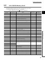
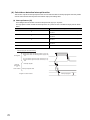
3.5
List of Buffer Memory Areas
The following table lists the buffer memory areas of the high-speed counter module.
For details on the buffer memory areas, refer to the following.
• Details of Buffer Memory Areas (
Address
Address
(decimal)
(hexadecimal)
0
0H
1
1H
Page 116, Appendix 2)
Initial value*1
Read/write*2
CH1 Preset value (L)*3
0
R/W
CH1 Preset value (H) *3
Name
0
R/W
*3
0
R
(H)*3
0
R
2
2H
3
3H
CH1 Present value
4
4H
CH1 Coincidence output point No.1 (L)*3
0
R/W
5
5H
CH1 Coincidence output point No.1 (H)*3
0
R/W
6
6H
CH1 Coincidence output point No.2 (L)*3
0
R/W
7
7H
CH1 Coincidence output point No.2 (H)*3
0
R/W
8
8H
CH1 Overflow detection
0
R
9
9H
CH1 Counter function selection
0
R/W
10
AH
CH1 Sampling/periodic time setting
0
R/W
11
BH
CH1 Sampling/periodic counter flag
0
R
0
R
12
CH
13
DH
CH1 Present value (L)
CH1 Latch count value (L)
CH1 Latch count value
*3
(H)*3
0
R
*3
0
R
EH
CH1 Sampling count value (L)
15
FH
CH1 Sampling count value (H)*3
0
R
16
10H
CH1 Periodic pulse count previous value (L)*3
0
R
17
11H
CH1 Periodic pulse count previous value (H)*3
0
R
18
12H
CH1 Periodic pulse count present value (L)*3
0
R
13H
*3
19
0
R
*3
0
R/W
CH1 Periodic pulse count present value (H)
20
14H
CH1 Ring counter lower limit (L)
21
15H
CH1 Ring counter lower limit (H)*3
0
R/W
22
16H
CH1 Ring counter upper limit (L)*3
0
R/W
23
17H
CH1 Ring counter upper limit (H)*3
0
R/W
24
18H
to
to
System area
31
1FH
32
20H
CH2 Preset value (L)*3
0
R/W
33
21H
CH2 Preset value (H) *3
0
R/W
34
22H
CH2 Present value (L) *3
0
R
35
23H
CH2 Present value (H)*3
36
24H
CH2 Coincidence output point No.1 (L)
0
R
*3
0
R/W
*3
0
R/W
37
25H
CH2 Coincidence output point No.1 (H)
38
26H
CH2 Coincidence output point No.2 (L)*3
0
R/W
39
27H
CH2 Coincidence output point No.2 (H)*3
0
R/W
3.5 List of Buffer Memory Areas
14
3
27
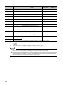
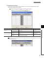
Address
Address
(decimal)
(hexadecimal)
40
28H
41
29H
42
Initial value*1
Read/write*2
CH2 Overflow detection
0
R
CH2 Counter function selection
0
R/W
2AH
CH2 Sampling/periodic time setting
0
R/W
43
2BH
CH2 Sampling/periodic counter flag
44
2CH
Name
CH2 Latch count value
0
R
(L)*3
0
R
*3
45
2DH
CH2 Latch count value (H)
0
R
46
2EH
CH2 Sampling count value (L)*3
0
R
47
2FH
CH2 Sampling count value (H)*3
0
R
48
30H
CH2 Periodic pulse count previous value (L)*3
0
R
49
31H
CH2 Periodic pulse count previous value (H)*3
32H
50
51
33H
52
CH2 Periodic pulse count present value (L)
0
R
*3
0
R
*3
0
R
34H
CH2 Ring counter lower limit
(L)*3
0
R/W
53
35H
CH2 Ring counter lower limit (H)*3
0
R/W
54
36H
CH2 Ring counter upper limit (L)*3
0
R/W
55
37H
CH2 Ring counter upper limit (H)*3
0
R/W
56
38H
to
to
System area
63
3FH
*1
*2
*3
CH2 Periodic pulse count present value (H)
This value is set when the high-speed counter module is powered on or the CPU module is reset.
Whether a value can be read from/written to a program or not is indicated.
R: Readable
W: Writable
Read or write values in 32-bit signed binary. (Be sure to use two words at a time.)
● The system areas listed above and the areas not listed above are used by the system and are not available for users. If
data are written by a user, the performance of the high-speed counter module is not guaranteed.
● Buffer memory data in the high-speed counter module are initialized when the high-speed counter module is powered on
or the CPU module is reset. To save the necessary data, read/write the data by executing the FROM/DFRO/TO/DTO
instructions in the program or performing auto refresh to the device data.
28
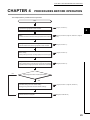
CHAPTER 4 PROCEDURES BEFORE OPERATION
CHAPTER 4
PROCEDURES BEFORE OPERATION
This chapter lists the procedures before operation.
Start
Module installation
Connect the high-speed counter module.
(
Wiring
Connect an external device to the high-speed counter module.
(
Page 35, Section 6.2, Page 47, Section 6.3, Page 49,
Section 6.4)
Adding the model name of the intelligent function module
Page 31, Section 5.1)
4
(
Page 53, Section 7.1)
Switch setting
Set a pulse input mode, counting speed, and counter type.
(
Page 54, Section 7.2)
Intelligent function module detailed setting
Set an output mode if a CPU stop error occurs and CPU module
operation mode if a high-speed counter module error is detected.
(
Page 55, Section 7.3)
Parameter setting and auto refresh setting
Configure the parameter and auto refresh settings.
(
Page 56, Section 7.4, Page 57, Section 7.5)
Programming and debugging
Create and check a program.
(
Page 88, CHAPTER 10)
Add the model name of the high-speed counter module.
NO
Use intelligent function module parameters?
YES
29
Memo
30
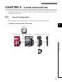
CHAPTER 5 SYSTEM CONFIGURATION
CHAPTER 5
SYSTEM CONFIGURATION
This chapter describes the overall configuration, number of connectable modules, and compatible software versions of
the high-speed counter module.
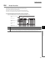
5.1
Overall Configuration
The following figures show examples of system configuration using the high-speed counter module.
(1) When connected to the CPU module
5
Display unit
(optional)
Power supply module
CPU module
High-speed counter module
END cover
5.1 Overall Configuration
Connector
31
(2) When connected to the head module
Power supply module
Head module
High-speed counter module
Connector
32
END cover
CHAPTER 5 SYSTEM CONFIGURATION
5.2
Applicable System
(1) Number of connectable modules
For the number of connectable modules, refer to the following.
MELSEC-L CPU Module User's Manual (Hardware Design, Maintenance and Inspection)
MELSEC-L CC-Link IE Field Network Head Module User's Manual
(2) Compatible software versions
For compatible software versions, refer to the following.
MELSEC-L CPU Module User's Manual (Hardware Design, Maintenance and Inspection)
MELSEC-L CC-Link IE Field Network Head Module User's Manual
5.2.1
5
Restrictions when the high-speed counter module is
connected to the head module
The restrictions are as follows:
• The coincidence detection interrupt function cannot be used.
• Due to the link scan time, a delay occurs. This delay causes variations if the processing is carried out with
counter values that are input using a program. Thoroughly examine the system to make sure that it will not
cause controllability problem.
5.2 Applicable System
5.2.1 Restrictions when the high-speed counter module is connected to the head module
33
CHAPTER 6
INSTALLATION AND WIRING
This chapter describes installation and wiring of the high-speed counter module.
6.1
Installation Environment and Installation Position
For precautions for installation environment and installation position, refer to the following.
MELSEC-L CPU Module User's Manual (Hardware Design, Maintenance and Inspection)
MELSEC-L CC-Link IE Field Network Head Module User's Manual
34
CHAPTER 6 INSTALLATION AND WIRING
6.2
Wiring
This section describes wiring of encoders and controllers to the high-speed counter module.
6.2.1
Wiring precautions
To obtain the maximum performance from the functions of the high-speed counter module and improve the system
reliability, an external wiring with high durability against noise is required.
Here are some precautions when wiring encoders and controllers.
(1) Wiring
• Different terminals are prepared depending on the voltage of the signal to be input. Connecting to a terminal
with a different voltage may cause malfunction of the module or failure of the connected devices.
• In 1-phase input, always connect a pulse input cable on the A-phase side.
• Install a fuse for each external terminal to prevent the external devices or module from being burnt out or
6
damaged if a load shorts in an output circuit. The following fuses have been tested by Mitsubishi.
Fuse model name
Rated current
Contact
312.750
0.75A
Littlefuse KK
216.800
0.8A
www.littelfuse.com
(2) Connectors for external devices
• Connectors for external devices must be soldered or crimped properly. A poor soldering or crimping may
result in malfunction.
and securely tighten the two screws.
• When removing a cable from the high-speed counter module, do not pull the cable by the cable part.
Remove a cable supporting the connector part of the cable by hand. Pulling the cable being connected to the
high-speed counter module can cause malfunction. In addition, a damage of the high-speed counter module
or cables can result.
35
6.2 Wiring
6.2.1 Wiring precautions
• Securely connect the connectors for external devices to the connectors of the high-speed counter module,
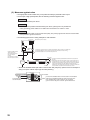
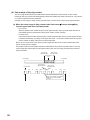
(3) Measures against noise
• The high-speed counter module may count pulses incorrectly if pulse-like noise is input.
• For the input of high-speed pulses, take the following measures against noise:
Measure 1
Use shielded twisted pair cables.
Measure 2
Use the shortest possible shielded twisted pair cables, placing them not parallel with
noise-generating power cables or I/O cables and at a distance of 150mm or more.
Measure3
Ground the shield cable on the encoder side (relay box). Always ground the FG and LG terminals
to the protective ground conductor.
• The following figure shows a wiring example for noise reduction.
Programmable
controller
High-speed counter module
Inverter
Terminal
block
Terminal
block
Install I/O cables at least
150mm away from
high voltage equipment
such as a relay or
inverter.
(Pay attention to wiring in
the control panel as well.)
Avoid using a solenoid valve or inductive load together with the cable in a metallic pipe.
If a sufficient distance from the power line cannot be ensured due to duct wiring,
use shielded cables such as CVVS for the power line.
Relay box
AC motor
Cart
Encoder
Provide the shortest possible distance between the encoder and
relay box.
If the distance from the high-speed counter to the encoder is long,
a voltage drop may occur. Using a measuring instrument such as
a tester on the terminal block of the relay box, check if the voltages
in the encoder operation and stop status are within the rated
voltage range. If a voltage drop is too large, increase the cable size
or use a 24VDC encoder that will consume less current.
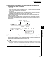
• Ground the shielded twisted pair cable on the encoder side (relay box). (Shown here is an example of
wiring to an open collector output type encoder (24VDC).)
+24V
Current for encoder
To A
To B
To the high-speed
counter module
36
To the encoder
0V
A
B
24V
E
E
Connect the shielded cable of the encoder to the shielded
cable of the shielded twisted pair cable in the relay box.
If the shielded wire of the encoder is not grounded,
ground it to the relay box as shown by the dotted lines.
CHAPTER 6 INSTALLATION AND WIRING
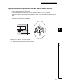
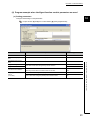
(4) Requirements for compliance with the EMC and Low Voltage Directives
Take the following measures for compliance with the EMC and Low Voltage Directives.
• Install a DC power inside the control panel.
• Use a shielded cable for the DC power when the cable is extended out of the control panel.
• Keep the length of the cables between the high-speed counter module and the external devices to 30m or
less.
• Use a shielded twisted pair cable and ground the shielded part of the cable to the control panel with the
AD75CK-type cable clamping (Mitsubishi).
Inside of control panel
High-speed
counter module
6
20 to 30cm
AD75CK
For details on the AD75CK, refer to the following.
AD75CK-type Cable Clamping Instruction Manual
6.2 Wiring
6.2.1 Wiring precautions
37
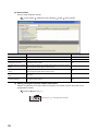
• Take the following noise reduction measures when wiring a connector for external devices.
[Example of wiring using a shielded cable]
The following figure shows an example of wiring for noise reduction using the A6CON1.
Connector
(A6CON1)
From the controller
Shielded
cable
From the encoder
To the external device
To the high-speed counter module
The length between the connector
and shielded cables should be the
shortest possible.
Ground the shortest possible FG wire of 2mm2 or more.
(Ground it to the panel on the high-speed counter module
side.)
[Example of noise reduction measures taken to shielded cables]
Take off the jacket of each shield and connect
Coat the connector pins with heatshrinkable insulation
the shields of the cables with conductive tapes.
tubes to protect signal lines.
(Exposure of signal lines may cause malfunction
due to static electricity.)
Cover the wires with
an insulating tape.
Take a shield out from any of the shielded cables,
and solder it to the FG wire.
Assembling the A6CON1
Cover the wires and conductive tape
with a heatshrinkable tube.
38
CHAPTER 6 INSTALLATION AND WIRING
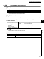
6.2.2
Connectors for external devices
(1) Precautions
• Tighten the connector screws within the specified torque range.
Screw
Tightening torque range
Connector screw (M2.6)
0.20 to 0.29Nm
• Use copper wires having temperature rating of 75 or more for the connectors.
• Use UL listed connectors if necessary for UL compliance.
(2) Applicable connectors
Connectors for external devices that are applicable to the high-speed counter module need to be obtained by a
user.
The following tables list the applicable connectors, and the reference product of a crimping tool.
(a) 40-pin connectors
Type
Model
Soldering type connector
(straight out type)
Crimping type connector
(straight type)
Soldering type connector
(dual purpose (straight/oblique) type)
6
Applicable wire size
A6CON1
0.3 (22 AWG) (Stranded)
A6CON2
0.088 to 0.24 (28 to 24 AWG) (stranded wire)
A6CON4
0.3 (22 AWG) (Stranded)
6.2 Wiring
6.2.2 Connectors for external devices
The A6CON3 (IDC type connector (straight type)) cannot be used.
(b) 40-pin connector crimping tool
Type
Crimping tool
Model
FCN-363T-T005/H
Contact
FUJITSU COMPONENT LIMITED
www.fcl.fujitsu.com/en
For how to wire the connector and how to use the crimping tool, contact the manufacturer.
39
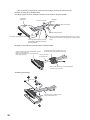
(3) Wiring method
For wiring method, refer to the following.
MELSEC-L CPU Module User's Manual (Hardware Design, Maintenance and Inspection)
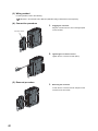
(4) Connection procedure
1.
Plugging the connector
Plug the connector into the slot on the high-speed
counter module.
Connector screw
2.
Tightening the connector screws
Tighten the two connector screws (M2.6).
(5) Removal procedure
1.
Removing the connector
Loosen the two connector screws and pull out the
connector from the module.
40
CHAPTER 6 INSTALLATION AND WIRING
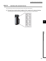
6.2.3
Interface with external devices
This section lists the interface of the high-speed counter module with external devices.
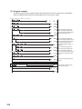
(1) Terminal layout and terminal numbers of the connector for external devices
The following figure shows the terminal layout and numbers on the connector for external devices.
B20
B19
B18
B17
B16
B15
B14
B13
B12
B11
B10
B09
B08
B07
B06
B05
B04
B03
B02
B01
A20
A19
A18
A17
A16
A15
A14
A13
A12
A11
A10
A09
A08
A07
A06
A05
A04
A03
A02
A01
6
6.2 Wiring
6.2.3 Interface with external devices
41
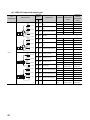
(2) LD62 (DC input sink output type)
Terminal
I/O
classification
Internal circuit
CH1
6.8kΩ
1/3W
3.9kΩ
1/4W
330Ω
1/4W
A20
3.9kΩ
1/4W
330Ω
1/4W
Input
10kΩ
1/3W
5.6kΩ
1/10W
2kΩ
1kΩ 1/8W
1/10W
10kΩ
1/3W
5.6kΩ
1/10W
2kΩ
1kΩ 1/8W
1/10W
42
Signal name
A13
A17,A10
24V
Off
5V or less
0.1mA or less
Phase A pulse input
On
10.8 to 13.2V
2 to 5mA
12V
Off
4V or less
0.1mA or less
B13
A19
A12
Phase A pulse input 5V
B19
B12
ABCOM
A18
A11
Off
5V or less
0.1mA or less
Phase B pulse input
On
10.8 to 13.2V
2 to 5mA
12V
Off
4V or less
0.1mA or less
On
4.5 to 5.5V
2 to 5mA
Off
2V or less
0.1mA or less
On
21.6 to 26.4V
2 to 5mA
Off
5V or less
0.1mA or less
On
10.8 to 13.2V
2 to 5mA
Off
4V or less
0.1mA or less
On
4.5 to 5.5V
2 to 5mA
Off
2V or less
0.1mA or less
Response
Off to on
On to off
time
0.5ms or less
1ms or less
On
21.6 to 26.4V
2 to 5mA
Off
5V or less
0.1mA or less
On
10.8 to 13.2V
2 to 5mA
Off
4V or less
0.1mA or less
On
4.5 to 5.5V
2 to 5mA
Off
2V or less
0.1mA or less
Response
Off to on
On to off
time
0.5ms or less
1ms or less
Phase B pulse input 5V
B17
B10
Preset input 24V
A16
A09
Preset input 12V
B16
B09
Preset input 5V
A15
A08
CTRLCOM
B15,B08
B15
B08
Function start input 24V
0.1mA or less
21.6 to 26.4V
A10
B07
2 to 5mA
2V or less
On
A17
B14
4.5 to 5.5V
Off
24V
A15,A08
B14,B07
On
Phase B pulse input
B11
A07
2 to 5mA
B18
A14
value)
21.6 to 26.4V
A16,A09
A14,A07
current
(guaranteed
On
B17,B10
B16,B09
Operating
Phase A pulse input
A19,A12
B18,B11
(guaranteed
value)
B20
B20,B13
A18,A11
Operation
CH2
A20,A13
B19,B12
6.8kΩ
1/3W
Input voltage
number*1
Function start input 12V
Function start input 5V
2 to 5mA
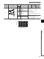
CHAPTER 6 INSTALLATION AND WIRING
Terminal
I/O
classification
Internal circuit
A06,A05
CH1
CH2
A06
A05
Operating
Input voltage
number*1
Signal name
Operation
(guaranteed
value)
current
(guaranteed
value)
EQU1
• Operating voltage: 10.2 to 30V
(coincidence output
• Maximum load current: 0.5A/point,
point No.1)
2A/common*2
• Maximum voltage drop at on: 1.5V
B06,B05
• Response time
EQU2
B06
Output
B05
B02,B01
(coincidence output
Off to on: 0.1ms or less
point No.2)
On to off: 0.1ms or less (rated load, resistive
load)
A02,A01
B02, B01
12/24V
• Input voltage: 10.2 to 30V
• Current consumption: 43mA
A02, A01
(TYP., 24VDC and all points on/common)
0V
• Common to all channels
The terminals A03, A04, B03, and B04 are not assigned.
Coincidence output derating (on ratio) is as follows.
6
100
ON ratio (%)
*1
*2
90
80
70
60
50
40
30
0
10
20
30
40
Ambient temperature (
50 55
)
6.2 Wiring
6.2.3 Interface with external devices
43
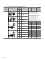
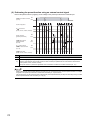
(3) LD62D (differential input sink output type)
Terminal
I/O
number*1
Internal circuit
classification
+5V
+5V
27kΩ
1/10W 4.7kΩ
1/10W
100Ω
1/2W
Digital
isolator
Line
receiver
4.7kΩ
1/10W
27kΩ
1/10W
CH1
CH2
A20
A14
Input voltage
Signal name
Operation
(guaranteed
value)
Phase A pulse input
Operating
current
(guaranteed
value)
EIA Standard RS-422-A Line receiver
(AM26C32 (manufactured by Texas
A20,A14
Instruments Incorporated) or equivalent)
B20,B14
B20
B14
Phase A pulse input
The line receiver specifications are as follows:
• VIT + Differential input on voltage
+5V
+5V
Digital
isolator
27kΩ
1/10W 4.7kΩ
1/10W
A19,A13
100Ω
1/2W
B19,B13
4.7kΩ
Line
1/10W
receiver
27kΩ
1/10W
10kΩ
1/3W
Input
1kΩ
1/10W
5.6kΩ
1/10W
680Ω
1/10W
1kΩ
1/10W
5.6kΩ
1/10W
680Ω
1/10W
Phase B pulse input
(H level threshold voltage) 0.2V
• VIT - Differential input off voltage
(L level threshold voltage) - 0.2V
B19
B13
Phase B pulse input
A18
A12
Preset input 24V
B18
B12
Preset input 12V
B18,B12
A17
A11
Preset input 5V
B17
B11
PRSTCOM
A16
A10
Function start input 24V
B16
B10
Function start input 12V
A17,A11
A16,A10
B16,B10
A15
A09
Function start input 5V
B15
B09
FUNCCOM
A15,A09
B15,B09
44
A13
A18,A12
B17,B11
10kΩ
1/3W
A19
• Vhys hysteresis voltage (VIT +- VIT -) 60mV
(Current type line driver cannot be used.)
On
21.6 to 26.4V
2 to 5mA
Off
5V or less
0.1mA or less
On
10.8 to 13.2V
2 to 5mA
Off
4V or less
0.1mA or less
On
2.5 to 5.5V
2 to 5mA
Off
1V or less
0.1mA or less
Response
Off to on
On to off
time
0.5ms or less
1ms or less
On
21.6 to 26.4V
2 to 5mA
Off
5V or less
0.1mA or less
On
10.8 to 13.2V
2 to 5mA
Off
4V or less
0.1mA or less
On
2.5 to 5.5V
2 to 5mA
Off
1V or less
0.1mA or less
Response
Off to on
On to off
time
0.5ms or less
1ms or less
CHAPTER 6 INSTALLATION AND WIRING
Terminal
I/O
classification
Internal circuit
CH1
CH2
A06
A05
A06,A05
Operating
Input voltage
number*1
Signal name
Operation
(guaranteed
value)
current
(guaranteed
value)
EQU1
• Operating voltage: 10.2 to 30V
(coincidence output
• Maximum load current: 0.5A/point,
point No.1)
2A/common*2
• Maximum voltage drop at on: 1.5V
• Response time
EQU2
B06,B05
Output
B06
B05
(coincidence output
Off to on: 0.1ms or less
point No.2)
On to off: 0.1ms or less (rated load, resistive
load)
B02,B01
B02, B01
12/24V
• Input voltage: 10.2 to 30V
A02,A01
• Current consumption: 43mA
A02, A01
(TYP., 24VDC and all points on/common)
0V
• Common to all channels
The terminals A03, A04, A07, A08, B03, B04, B07, and B08 are not assigned.
Coincidence output derating (on ratio) is as follows.
6
100
ON ratio (%)
*1
*2
90
80
70
60
50
40
30
0
10
20
30
40
Ambient temperature (
50 55
)
6.2 Wiring
6.2.3 Interface with external devices
45
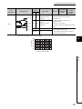
6.2.4
Connectable encoders
Encoders that can be connected to the high-speed counter module are as follows.
(1) To the LD62
• Open collector output type encoder
• CMOS level voltage output type encoder
(Check that the encoder output voltage meets the specifications of the LD62.)
(2) To the LD62D
• Line driver output type encoder
(Check that the encoder output voltage meets the specifications of the LD62D.)
The following encoder cannot be used with the high-speed counter module.
● TTL level voltage output type encoder
46
CHAPTER 6 INSTALLATION AND WIRING
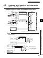
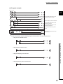
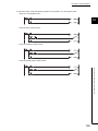
6.3
Examples of Wiring Between the High-Speed Counter
Module and an Encoder
(1) Example of wiring with an open collector output type encoder (24VDC)
LD62
24V
A20(A13)
OUT
12V
B20(B13)
Phase A
Encoder
Shielded twisted pair cable
+24V
Shield
5V
A19(A12)
E
ABCOM
B19(B12)
24V
A18(A11)
Shielded twisted pair cable
12V
B18(B11)
Phase B
OUT
6
+24V
Shield
5V
A17(A10)
E
+24V
24VDC
External power supply
0V
0V
For the wiring between the RD62 and an encoder, separate the power supply cables and the signal cables. The following
figures show its examples:
● Example of correct wiring
LD62
Phase A
24V
Shielded twisted pair cable
ABCOM
OUT
+24V
Shield
0V
Encoder
E
External
power supply
24VDC
0V
● Example of inappropriate wiring
Shielded twisted pair cable
LD62
24V
OUT
Phase A
+24V
ABCOM
Shield
0V
E
Encoder
Because currents flow in
the same direction in the
shielded twisted pair cable,
canceling effect will be lost
and electromagnetic
induction may occur.
24VDC
External
power supply
0V
47
6.3 Examples of Wiring Between the High-Speed Counter Module and an Encoder
In parentheses, terminal numbers of channel 2 are shown.
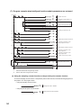
(2) Example of wiring with a voltage output type encoder (5VDC)
LD62
Encoder
24V
A20(A13)
12V
B20(B13)
Phase A
Shielded twisted pair cable
5V
A19(A12)
OUT
GND
Shield
ABCOM
B19(B12)
E
24V
A18(A11)
12V
B18(B11)
Phase B
Shielded twisted pair cable
5V
A17(A10)
OUT
GND
Shield
E
+5V
5VDC
External power supply
0V
0V
In parentheses, terminal numbers of channel 2 are shown.
(3) Example of wiring with a line driver (equivalent to AM26LS31) encoder
Encoder
LD62D
A
A20(A14)
Phase
A
Digital
isolator
A
B20(B14)
Shielded twisted pair cable
A
A
Shield
E
B
A19(A13)
Phase
B
Digital
isolator
B
B19(B13)
Shielded twisted pair cable
B
B
Shield
E
VCC
External power supply
0V
VCC
0V
In parentheses, terminal numbers of channel 2 are shown.
48
CHAPTER 6 INSTALLATION AND WIRING
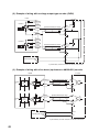
6.4
Examples of Wiring Between a Controller and External
Input Terminals
(1) When the controller (sync load type) has a voltage of 12VDC
Controller
LD62
24V
B17(B10)
Preset
12V
A16(A09)
5V
B16(B09)
Shielded twisted pair cable
Shield
OUT
+12V
E
CTRLCOM
A15(A08)
6
24V
B15(B08)
Function start
12V
A14(A07)
5V
B14(B07)
Shielded twisted pair cable
Shield
OUT
+12V
E
6.4 Examples of Wiring Between a Controller and External Input Terminals
12VDC
In parentheses, terminal numbers of channel 2 are shown.
Controller
LD62D
Preset
24V
A18(A12)
12V
B18(B12)
5V
A17(A11)
Shielded twisted pair cable
Shield
PRSTCOM
B17(B11)
Function start
OUT
+12V
E
24V
A16(A10)
12V
B16(B10)
5V
A15(A09)
FUNCCOM
B15(B09)
Shielded twisted pair cable
Shield
OUT
+12V
E
12VDC
In parentheses, terminal numbers of channel 2 are shown.
49
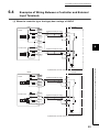
(2) When the controller (source load type) has a voltage of 5VDC
Controller
LD62
24V
B17(B10)
Preset
12V
A16(A09)
5V
B16(B09)
Shielded twisted pair cable
OUT
GND
CTRLCOM
A15(A08)
Function start
Shield
E
24V
B15(B08)
12V
A14(A07)
5V
B14(B07)
Shielded twisted pair cable
OUT
GND
Shield
E
5VDC
In parentheses, terminal numbers of channel 2 are shown.
Controller
LD62D
Preset
24V
A18(A12)
12V
B18(B12)
5V
A17(A11)
Shielded twisted pair cable
OUT
GND
PRSTCOM
B17(B11)
Function start
Shield
E
24V
A16(A10)
12V
B16(B10)
5V
A15(A09)
Shielded twisted pair cable
OUT
GND
FUNCCOM
B15(B09)
Shield
E
5VDC
In parentheses, terminal numbers of channel 2 are shown.
50
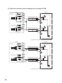
CHAPTER 6 INSTALLATION AND WIRING
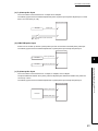
(3) When the controller is a line driver type
LD62D
24V
A18(A12)
Preset
Controller
12V
B18(B12)
5V
A17(A11)
Shielded twisted pair cable
PRSTCOM
B17(B11)
OUT
OUT
Shield
E
24V
A16(A10)
Function start
12V
B16(B10)
5V
A15(A09)
Shielded twisted pair cable
FUNCCOM
B15(B09)
OUT
6
OUT
Shield
E
In parentheses, terminal numbers of channel 2 are shown.
6.4 Examples of Wiring Between a Controller and External Input Terminals
51
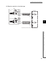
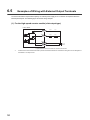
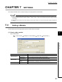
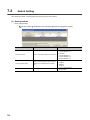
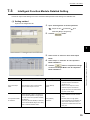
6.5
Examples of Wiring with External Output Terminals
To use the coincidence output terminal (EQU), an external power supply of 10.2 to 30VDC is required to drive the
internal photocoupler. The following figure shows the wiring example:
(1) For the high-speed counter module (sink output type)
LD62, LD62D
EQU1
A06(A05)
Fuse*1
Load
EQU2
B06(B05)
Fuse*1
Load
12/24V
B02, B01
0V
A02, A01
10.2 to
30VDC
In parentheses, terminal numbers of channel 2 are shown.
*1
52
Install a fuse for each external terminal to prevent the external devices or module from being burnt out or damaged if a
load shorts in an output circuit.
CHAPTER 7 SETTINGS
CHAPTER 7
SETTINGS
This chapter describes how to configure settings of the high-speed counter module.
● After writing the contents of the new module, parameter settings, and auto refresh settings into the CPU module, reset
the CPU module and switch its status as STOP RUN STOP RUN, or turn off and on the power supply to activate
the settings.
● After writing the contents of the switch settings, reset the CPU module or turn off and on the power supply to activate the
settings.
7.1
Adding a Module
Add the model name of the high-speed counter module used for the project.
(1) How to add a module
7
Open "New Module".
Project window
[Intelligent Function Module]
Right-click
[New Module...]
7.1 Adding a Module
Item
Module Selection
Mount Position
Title Setting
Description
Module Type
Select "Counter Module".
Module Name
Select the model name of the module to be connected.
Mounted Slot No.
Select the number of the slot where the module is mounted.
Specify start XY
The start I/O number (hexadecimal) of the module mounted on the slot set to
address
"Mounted Slot No." is displayed. This item can be set by user.
Title
Enter a title.
53
7.2
Switch Setting
Set a pulse input mode, counting speed, and counter type for each channel.
(1) Setting method
Open "Switch Setting".
Project window
[Intelligent Function Module]
Item
Model name
[Switch Setting]
Description
Setting value
• 1-Phase Multiple of 1 (default)
• 1-Phase Multiple of 2
Pulse input mode
Select a pulse input mode for each channel.
• CW/CCW
• 2-Phase Multiple of 1
• 2-Phase Multiple of 2
• 2-Phase Multiple of 4
Select a counting speed for each channel.
Counting speed setting
500kpps can be selected for the LD62D
only.
Counter format
54
Select a counter type for each channel.
• 10kpps (default)
• 100kpps
• 200kpps
• 500kpps
• Linear Counter (default)
• Ring Counter
CHAPTER 7 SETTINGS
7.3
Intelligent Function Module Detailed Setting
Perform an output mode setting for an error and CPU module operation mode setting for a hardware error.
(1) Setting method
Open the "I/O Assignment" tab.
1.
Open "I/O Assignment" of the PLC parameter.
Project window
Parameter]
2.
[Parameter]
[PLC
[I/O Assignment]
Click the
button.
7
3.
Select "Clear" or "Hold" for "Error Time Output
Mode".
4.
Select "Stop" or "Continue" for "PLC Operation
5.
Click the
button to complete the settings
of "Error Time Output Mode" and "PLC Operation
Mode at H/W Error".
Item
Description
Setting value
Remarks
• Clear: If a CPU stop error occurs, all
external outputs of coincidence
Error Time Output
Select whether to clear or hold module
• Clear (default)
Mode
output if a CPU stop error occurs.
• Hold
signals turn off.
• Hold: If a CPU stop error occurs,
external outputs of coincidence
signals are held in the status before
the CPU module stops.
• Stop: If a high-speed counter module
• Select whether to stop or continue the
error is detected, the CPU module
CPU module operation if a high-speed
PLC Operation Mode
at H/W Error
counter module error (SP.UNIT DOWN)
is detected.
• The error (SP.UNIT DOWN) is detected
if the module READY flag is not in ready
due to module hardware failure.
stops.
• Stop (default)
• Continue
• Continue: Even if a high-speed
counter module error is detected, the
CPU module continues running a
program for modules other than the
faulty one.
55
7.3 Intelligent Function Module Detailed Setting
Mode at H/W Error".
7.4
Parameter Settings
Set parameters for each channel.
Setting parameters here eliminates the need to program them.
(1) Setting method
Open the "Parameter" window.
1.
Open the "Parameter" window from the project window.
Project window
[Intelligent Function Module]
Model name
[Parameter]
Item to be input in a text box
Item to be selected
from the pull-down list
2.
Double-click the text box of the setting-target item and select or enter a value.
• Items to be set by selecting a value from a pull-down list
Double-click the text box and select an option from the displayed pull-down list.
• Items to be set by entering a value in a text box
Double-click the text box and enter a value.
3.
When using CH2, perform the procedure 2.
Item
Preset value
Coincidence output point
No.1
Basic setting
Coincidence output point
No.2
Setting value
-2147483648 to 2147483647 (default: 0)
Reference
Page 73, Section 8.4
-2147483648 to 2147483647 (default: 0)
Page 68, Section 8.3
-2147483648 to 2147483647 (default: 0)
Ring counter upper limit
-2147483648 to 2147483647 (default: 0)
Ring counter lower limit
-2147483648 to 2147483647 (default: 0)
Page 65, Section 8.2.2
0: Count Disable Function (default)
Counter function selection
Counter function
2: Sampling Counter Function
3: Periodic Pulse Counter Function
Sampling/periodic time
setting
56
1: Latch Counter Function
1 to 65535 (unit: 10ms) (default: 0)
Page 75, Section 8.5
CHAPTER 7 SETTINGS
7.5
Auto Refresh
The function of auto refresh is to transfer buffer memory data to a specified device.
This setting eliminates the need to read data with a program.
(1) Setting method
Open the "Auto_Refresh" window.
1.
Open the "Auto_Refresh" window from the project window.
Project window
2.
[Intelligent Function Module]
Model name
[Auto_Refresh]
Click the text box of the setting-target item and enter the auto refresh target device.
7
7.5 Auto Refresh
57
CHAPTER 8
FUNCTIONS
This chapter describes the details of the functions that can be achieved through the high-speed counter module and
their setting methods.
For details on I/O signals and buffer memory, refer to the following.
• Details of I/O signals (
Page 112, Appendix 1)
• Details of Buffer Memory Areas (
58
Page 116, Appendix 2)
CHAPTER 8 FUNCTIONS
8.1
Pulse Input Modes and Counting Methods
This section describes the pulse input modes and the counting methods.
8.1.1
Types of pulse input modes
The following six pulse input modes are prepared: 1-phase pulse input (1 multiple/2 multiples), CW/CCW pulse input,
and 2-phase pulse input (1 multiple/2 multiples/4 multiples).
(1) Pulse input modes and count timing
Pulse input mode
Count timing
A
At up count
B and
CH Down
count command
(Y3, YB)
At down count
B or
CH Down
count command
(Y3, YB)
Counts on the rising edge () of A.
B and CH Down count command (Y3, YB) are off.
1-phase multiple of 1
A
At up count
B and
CH Down
count command
(Y3, YB)
B or CH Down count command (Y3, YB) is on.
8
Counts on the rising edge () and the falling edge ()
of A.
B and CH Down count command (Y3, YB) are off.
1-phase multiple of 2
A
At down count
At up count
B or
CH Down
count command
(Y3, YB)
A
Counts on the rising edge () and the falling edge ()
of A.
B or CH Down count command (Y3, YB) is on.
Counts on the rising edge () of A.
B is off.
B
CW/CCW
At down count
A
A is off.
Counts on the rising edge () of B.
B
At up count
A
Counts on the rising edge () of A while B is off.
B
2-phase multiple of 1
At down count
A
Counts on the falling edge () of A while B is off.
B
59
8.1 Pulse Input Modes and Counting Methods
8.1.1 Types of pulse input modes
A
Counts on the falling edge () of A.
Pulse input mode
Count timing
At up count
A
Counts on the rising edge () of A while B is off.
Counts on the falling edge () of A while B is on.
B
2-phase multiple of 2
At down count
A
Counts on the rising edge () of A while B is on.
Counts on the falling edge () of A while B is off.
B
Counts on the rising edge () of A while B is off.
At up count
A
Counts on the falling edge () of A while B is on.
Counts on the rising edge () of B while A is on.
B
2-phase multiple of 4
Counts on the falling edge () of B while A is off.
Counts on the rising edge () of A while B is on.
At down count
A
Counts on the falling edge () of A while B is off.
Counts on the rising edge () of B while A is off.
B
Counts on the falling edge () of B while A is on.
For the 1-phase pulse input, check that for up count, the phase B pulse input and CH Down count command (Y3, YB) are
off before performing the phase A pulse input.
If at least one of the B phase pulse input and CH Down count command (Y3, YB) is on, pulses are counted down in the A
phase pulse input.
60
CHAPTER 8 FUNCTIONS
(a) 1-phase pulse input
The count method can be selected from 1 multiple and 2 multiples.
The following figure shows the relationship between phase A pulse input and phase B pulse input or CH
Down count command (Y3, YB).
High-speed counter module
Encoder
Pulse input
A
B
B or CH
(Y3, YB)
Down count command
(b) CW/CCW pulse input
Pulses can be counted up with the A phase pulse input and counted down with the B phase pulse input.
The following figure shows the relationship between A phase pulse input and B phase pulse input.
High-speed counter module
Encoder
Count-up pulse input
A
8
Encoder
Count-down pulse input
B
8.1 Pulse Input Modes and Counting Methods
8.1.1 Types of pulse input modes
(c) 2-phase pulse input
The count method can be selected from 1 multiple, 2 multiples, and 4 multiples.
The phase difference between the A phase pulse and B phase pulse determines whether the pulses are
counted up or down.
The following figure shows the relationship between A phase pulse input and B phase pulse input.
High-speed counter module
Phase A pulse input
A
Encoder
Phase B pulse input
B
61
8.1.2
Setting a counting method
Set a counting method by switch setting.
For details on the setting method, refer to the following.
• Switch Setting (
8.1.3
Page 54, Section 7.2)
Reading the present value
This section describes the details on the present value stored in the buffer memory and the count values selected from
the counter function selection, and their reading method.
(1) Storage location of the count value
The present value is always stored in CH Present value (Un\G2, Un\G3, Un\G34, Un\G35) regardless of the
counter function used.
When the latch counter, sampling counter, or periodic pulse counter function is performed, the count value is
stored in the corresponding buffer memory areas listed in the table below.
Counter function selection count value
Description
Present value
CH1
Buffer memory address
CH2
Latch count
Sampling
value
count value
Un\G2,
Un\G12,
Un\G3
Un\G13
Un\G34,
Un\G35
Periodic pulse
Periodic pulse
count
count current
previous value
value
Un\G14,
Un\G16,
Un\G18,
Un\G15
Un\G17
Un\G19
Un\G44,
Un\G46,
Un\G48,
Un\G50,
Un\G45
Un\G47
Un\G49
Un\G51
(2) Stored data
The present value and the counter function selection count values are stored in the buffer memory areas in 32-bit
signed binary.
The buffer memory data is automatically updated by counting operation. The latest count value can be read from
the buffer memory.
Read the present value and counter function selection count values by two words at a time.
If the values are read by one word at a time, the lower word data and the higher word data will be inconsistent when the
count value is updated during reading, and an incorrect count value may be read.
● Program example
● Inappropriate program example
The present value may change while CH1 Present value (L) (Un\G2) and CH1 Present value (H) (Un\G3) are read.
62
CHAPTER 8 FUNCTIONS
8.2
Selecting Counter Type
Select a counting method in the switch setting.
(1) Setting method
1.
Set "Counter format" to "Linear Counter" or "Ring Counter".
Project window
[Intelligent Function Module]
Model name
[Switch Setting]
8
Item
Linear counter
Description
Pulses are counted between -2147483648 (lower limit value) and
Page 64, Section 8.2.1
Pulses are repeatedly counted between the values stored in CH
Ring Counter
Ring counter lower limit (Un\G20, Un\G21, Un\G52, Un\G53) and
Page 65, Section 8.2.2
CH Ring counter upper limit (Un\G22, Un\G23, Un\G54, Un\G55).
63
8.2 Selecting Counter Type
2147483647 (upper limit value).
Reference
8.2.1
Linear counter function
(1) Operation of the linear counter
• This function counts pulses between -2147483648 (lower limit value) and 2147483647 (upper limit value).
• The preset function and the coincidence output function can be used together.
Present counter value
Overflow
+2147483647
0
Counting down
Counting up
-2147483648
Overflow
(2) Overflow error
• In linear counter, an overflow error occurs if the present counter value falls below -2147483648 (lower limit
value) in counting down or exceeds 2147483647 (upper limit value) in counting up.
• If an overflow error occurs, "1" is stored in CH Overflow detection (Un\G8, Un\G40), the counting operation
stops, and the present value does not change from -2147483648 or 2147483647 even if pulses are input.
• An overflow error can be cleared by performing the preset function.
• When the preset function is performed, "0" is stored in CH Overflow detection (Un\G8, Un\G40) and the
counting operation can be restarted.
• Overflow error status can be checked in the system monitor window. (
64
Page 108, Section 11.1 (1))
CHAPTER 8 FUNCTIONS
8.2.2
Ring counter function
(1) Operation of the ring counter
This function repeatedly counts pulses between the values stored in CH Ring counter lower limit (Un\G20,
Un\G21, Un\G52, Un\G53) and CH Ring counter upper limit (Un\G22, Un\G23, Un\G54, Un\G55).
In ring counter, an overflow error does not occur.
The preset function and the coincidence output function can be used together.
Present counter value
+2147483647
CH
Ring counter upper limit (Un\G22, Un\G23, Un\G54, Un\G55)
0
Counting down
Counting up
CH
Ring counter lower limit (Un\G20, Un\G21, Un\G52, Un\G53)
-2147483648
8
8.2 Selecting Counter Type
8.2.2 Ring counter function
65
(2) Count range of the ring counter
The count range is determined by the relationship between CH Present value (Un\G2, Un\G3, Un\G34,
Un\G35) and the ring counter lower limit/upper limit values when CH Count enable command (Y4, YC) is turned
on or when the preset function is performed.
Normally, the count range is "Ring counter lower limit value Present value Ring counter upper limit value".
(a) When the count range is Ring counter lower limit value Present value Ring
counter upper limit value (normally used)
• For up count
When the present value reaches the ring counter upper limit value, the ring counter lower limit value is
automatically stored in CH Present value (Un\G2, Un\G3, Un\G34, Un\G35).
• For down count
Even when the present value reaches the ring counter lower limit value, the ring counter lower limit value
is held as the lower limit, and "Ring counter upper limit value - 1" is stored in CH Present value (Un\G2,
Un\G3, Un\G34, Un\G35) at the next count-down pulse input.
Both in up count and in down count, the ring counter upper limit value is not stored in CH Present value
(Un\G2, Un\G3, Un\G34, Un\G35).
For example, when the count enable command is valid while the ring counter lower limit value is 0, the ring
counter upper limit value is 2000, and the present value is 500, the count range and the present value will
change as follows.
Ring counter
Ring counter
lower limit value
upper limit value
0
2000
Present value
500
2147483647
-2147483648
Counting range
Ring counter
upper limit value
Present value
500
501
to
1998
1999
(2000)
0
Ring counter
lower limit value
1
2
to
498
The ring counter upper limit value,
2000, is not stored in CH Present
value (Un\G2, Un\G3, Un\G34,
Un\G35).
66
499
CHAPTER 8 FUNCTIONS
(b) When the count range is "Present value < Ring counter lower limit value or ring
counter upper limit value < Present value"
• For up count
Even when the present value reaches the ring counter lower limit value, the ring counter lower limit value
is held as the lower limit, and "Ring counter upper limit value + 1" is stored in CH Present value (Un\G2,
Un\G3, Un\G34, Un\G35) at the next count-up pulse input.
• For down count
When the present value reaches the ring counter upper limit value, the ring counter lower limit value is
automatically stored in CH Present value (Un\G2, Un\G3, Un\G34, Un\G35).
Both in up count and in down count, the ring counter upper limit value is not stored in CH Present value
(Un\G2, Un\G3, Un\G34, Un\G35).
For example, when the count enable command is valid while the ring counter lower limit value is 0, the ring
counter upper limit value is 2000, and the present value is 3000, the count range and the present value will
change as follows.
Ring counter
lower limit value
0
Ring counter
upper limit value
2000
Present value
3000
-2147483648
2147483647
Counting range
Present value
3000
Counting range
Ring counter
upper limit value
3001 to 2147483647 -2147483648 to -2
-1
(2000)
0
Ring counter
lower limit value
2001
2002
8
to
2998
2999
(c) When the count range is "Ring counter lower limit value = Ring counter upper limit
value"
When this condition is established, the count range will be the full range (-2147483648 to 2147483647) which
can be expressed in 32-bit signed binary regardless of the present value.
● While CH Count enable command (Y4, YC) is on, even if a value is written to CH Ring counter lower limit (Un\G20,
Un\G21, Un\G52, Un\G53) or CH Ring counter upper limit (Un\G22, Un\G23, Un\G54, Un\G55), the stored value does
not change.
Turn off CH Count enable command (Y4, YC) before changing the ring counter upper/lower limit value.
● Turn off CH Count enable command (Y4, YC) before changing the count range by the preset function.
67
8.2 Selecting Counter Type
8.2.2 Ring counter function
The ring counter upper limit value,
2000, is not stored in CH
Present value (Un\G2, Un\G3,
Un\G34, Un\G35).
8.3
Coincidence Output Function
This function compares the present counter value with the preset coincidence output point setting value and outputs a
signal when they match.
Up to two coincidence outputs can be set for each channel.
When using external output of the coincidence signal, turn on CH Coincidence signal enable command (Y2, YA)
beforehand.
(1) Operation of the coincidence output
The I/O numbers (X/Y) and the buffer memory addresses in (1) are for coincidence output point No.1.
For those of coincidence output point No.2, refer to the following.
• List of I/O Signals (Page 26, Section 3.4)
• List of Buffer Memory Areas (Page 27, Section 3.5)
ON
CH Count enable command
(Y4, YC)
OFF
CH Coincidence signal enable
command (Y2, YA)
OFF
ON
Counter input pulse
CH Coincidence output point No.1
(Un\G4, Un\G5, Un\G36, Un\37)
CH Counter value small
(point No.1) (X3, XA)
1) 100
ON
OFF
2)
ON
CH Counter value coincidence
(point No.1) (X2, X9)
OFF
CH Coincidence signal No.1 reset
command (Y0, Y8)
OFF
3)
ON
4)
ON
CH Counter value large (point No.1)
OFF
(X1, X8)
CH Present value
(Un\G2, Un\G3, Un\G34, Un\35)
No.
1)
2)
0
1
2
to
98
99
100
101 102 103
Description
Write a coincidence output point setting value to CH Coincidence output point No.1 (Un\G4, Un\G5, Un\G36,
Un\G37) of the high-speed counter module in 32-bit signed binary.
When the count value matches with the coincidence output point setting value, CH Counter value small (point
No.1) (X3, XA) turns off and CH Counter value coincidence (point No.1) (X2, X9) turns on.
Turn on CH Coincidence signal No.1 reset command (Y0, Y8) to reset CH Counter value coincidence (point
3)
No.1) (X2, X9).
If CH Counter value coincidence (point No.1) (X2, X9) remains on, the next coincidence signal cannot be output.
4)
68
When the counter value exceeds the coincidence output point setting value, CH Counter value large (point No.1)
(X1, X8) turns on.
CHAPTER 8 FUNCTIONS
Perform the following before turning on CH Coincidence signal enable command (Y2, YA).
● Set different values between CH Coincidence output point No.1 (Un\G4, Un\G5, Un\G36, Un\G37) and CH Present
value (Un\G2, Un\G3, Un\G34, Un\G35) by any of the following ways:
• Changing the coincidence output point setting
• Changing the present value using the preset function
• Changing the present value by inputting a pulse
● Turn off, on, and then off CH Coincidence signal No.1 reset command (Y0, Y8).
When CH Coincidence signal enable command (Y2, YA) is turned on before counting operation or while the
coincidence output point setting value matches with the present value, coincidence output is performed.
● CH Counter value coincidence (point No.1) (X2, X9) is on immediately after the CPU module is powered on or is reset
because both CH Present value (Un\G2, Un\G3, Un\G34, Un\G35) and CH Coincidence output point No.1 (Un\G4,
Un\G5, Un\G36, Un\G37) are set to "0".
(2) Setting method
Set values for "Coincidence output point No.1" and "Coincidence output point No.2".
Project window
[Intelligent Function Module]
Model name
[Parameter]
8
8.3 Coincidence Output Function
Item
Setting range
Coincidence output point No.1
-2147483648 to 2147483647
Coincidence output point No.2
(3) Output status setting at a CPU stop error
If a CPU stop error occurs, the output status (clear/hold) of external output signals can be set.
The output status setting can be set in the intelligent function module detailed setting.
(a) Setting method
Set "Clear" or "Hold" for "Error Time Output Mode".
Project window
[Parameter]
[PLC Parameter]
[I/O Assignment]
button
69
(4) Coincidence detection interrupt function
This function outputs an interrupt request to the CPU module and starts an interrupt program when the present
counter value matches with the preset coincidence output point setting value.
(a) Interrupt factors (SI)
One intelligent function module can have interrupt factors (SI) up to 16 points.
The high-speed counter module has interrupt factors of 4 points for each coincidence output point as shown
below.
SI No.
0
1
2
3
4 to 15
Interrupt factor
Channel 1: Coincidence detection of coincidence output
point No.1
Channel 1: Coincidence detection of coincidence output
point No.2
Channel 2: Coincidence detection of coincidence output
point No.1
Channel 2: Coincidence detection of coincidence output
point No.2
Reserved
Interrupt program execution timing
CH
CH
Counter value coincidence (point No.1) (X2, X9)
Counter value coincidence (point No.2) (X6, XD)
CH
CH
Coincidence signal No.1 reset command (Y0, Y8)
Coincidence signal No.2 reset command (Y7, YF)
I/O signals
Internal
processing
of
CPU module
Interrupt request
Interrupt request clear
Program in CPU module
70
Interrupt program
CHAPTER 8 FUNCTIONS
(b) Setting interrupt pointers
Assign interrupt factors (SI) and the interrupt pointers of the CPU module in "Intelligent Function Module
Interrupt Pointer Setting" of "PLC Parameter".
Project window
[Parameter]
[PLC Parameter]
[PLC System]
[Intelligent Function Module Setting]
button
8
Item
Interrupt Pointer Count
Start I/O No.
Intelligent Module Side
Start SI No.
Enter the start number of the interrupt pointer of the
CPU module.
Enter the number of interrupt factors (SI).
Enter the start I/O number of the high-speed counter
module.
Enter the start number of the interrupt factor (SI) of
the high-speed counter module.
Setting range
50 to 255
1 to 4
0000H to 0FF0H
0 to 3
Ex. Assigning SI0 to SI3 of the high-speed counter module, whose start I/O number has been set to 20, to the
interrupt pointers I50 to I53
71
8.3 Coincidence Output Function
Interrupt Pointer Start No.
PLC Side
Description
(c) Using only a specific SI No.
• Setting in the intelligent function module interrupt pointer setting in the parameters
Interrupt factors are used starting from the start SI No. by the number of interrupt pointers set in the
"Intelligent Function Module Interrupt Pointer Setting" dialog box.
For example, when "1" is set for "Start SI No." and "2" is set for "Interrupt Pointer Count", only SI1 and SI2
are used.
When these settings are not configured, the interrupt function will not be used.
• Using the IMASK instruction
Using the IMASK instruction allows enabling or disabling interrupt program execution (interrupt mask) for
each interrupt pointer.
For details on the IMASK instruction, refer to the following.
MELSEC-Q/L Programming Manual (Common Instruction)
A coincidence detection interrupt occurs on the rising edge of the counter value coincidence signal (off to on).
Therefore, the next interrupt will not be requested unless the coincidence signal is reset and the counter value coincidence
signal is turned off.
72
CHAPTER 8 FUNCTIONS
8.4
Preset Function
This function overwrites the present counter value with the set value.
The set value is referred to as a preset value.
This function can be used to start counting pulses from the preset value.
The function can be performed using a program or an external control signal.
(1) Performing the preset function using a program
Perform the preset function by turning on CH Preset command (Y1, Y9).
CH Count enable command ON
OFF
(Y4, YC)
Counter input pulse
1)
CH Preset value
(Un\G0, Un\G1, Un\G32, Un\G33)
CH Preset command
(Y1, Y9)
1)
100
2)
ON
OFF
CH Present value
(Un\G2, Un\G3, Un\G34, Un\G35)
No.
0
0
1
2
to
65
66
67
100
101 102 103 104 105
8
Description
Write a value to CH Preset value (Un\G0, Un\G1, Un\G32, Un\G33) in 32-bit signed binary.
On the rising edge (off to on) of CH Preset command (Y1, Y9), the value stored in CH Present value (Un\G2,
2)
Un\G3, Un\G34, Un\G35) is replaced with the value stored in CH Preset value (Un\G0, Un\G1, Un\G32, Un\G33).
8.4 Preset Function
The preset function is performed regardless of the on/off status of CH Count enable command (Y4, YC).
73
(2) Performing the preset function using an external control signal
Perform the preset function by applying an ON voltage to the preset input terminal for external input.
CH Count enable command ON
OFF
(Y4, YC)
Counter input pulse
1)
CH Preset value
(Un\G0, Un\G1, Un\G32, Un\G33)
0
100
2)
Preset command
(preset input terminal)
ON
OFF
CH External preset
request detection
(X4, XB)
ON
OFF
CH External preset
detection reset command
(Y5, YD)
OFF
0
1
No.
1)
2)
4)
ON
CH Present value
(Un\G2, Un\G3, Un\G34, Un\G35)
3)
2
to
65
66
67
100 101 to 123 124 100 101
Description
Write a value to CH Preset value (Un\G0, Un\G1, Un\G32, Un\G33) in 32-bit signed binary.
On the rising edge (off to on) of the preset command (A voltage is applied to the preset input terminal.), the value
2)
stored in CH Present value (Un\G2, Un\G3, Un\G34, Un\G35) is replaced with the value stored in CH Preset
value (Un\G0, Un\G1, Un\G32, Un\G33).
The preset function is performed regardless of the on/off status of CH Count enable command (Y4, YC).
While CH External preset request detection (X4, XB) is on (3)), the preset function cannot be performed even if a voltage
is applied to the preset input terminal or CH Preset command (Y1, Y9) is turned on.
The preset function can be performed when CH External preset request detection (X4, XB) is turned off by turning on CH
External preset detection reset command (Y5, YD) (4)).
74
CHAPTER 8 FUNCTIONS
8.5
Counter Function Selection
The count disable function, the latch counter function, the sampling counter function, or the periodic pulse counter
function can be used by selecting each item in "Counter function selection". The selected counter function is performed
by the counter function selection start command (A voltage is applied to the function start input terminal or CH
Counter function selection start command (Y6, YE) is turned on by a program).
The counter function selection permits using only one function of the four counter functions.
(1) Setting method
Select a counter function in "Counter function selection".
Project window
[Intelligent Function Module]
Item
Model name
[Parameter]
Description
Reference
Count Disabling Function
Stops counting while CH Count enable command (Y4, YC) is on.
Page 78, Section 8.6
Latch Counter Function
Latches the present counter value when a signal is input.
Page 79, Section 8.7
Sampling Counter Function
Counts pulses input during the specified sampling period (T).
Page 80, Section 8.8
Stores the present and previous counter values to CH Periodic
Periodic Pulse Counter Function
pulse count present value (Un\G18, Un\G19, Un\G50, Un\G51) and
CH Periodic pulse count previous value (Un\G16, Un\G17,
Page 81, Section 8.9
8
Un\G48, Un\G49), respectively, at the preset cycle (T).
● The selected counter function can be performed by turning on CH Counter function selection start command (Y6, YE)
or applying a voltage to the function start input terminal. A signal that is input first takes priority.
● Time for the sampling counter function or the periodic pulse counter function can be set by writing a value of 1 to 65535
to CH Sampling/periodic time setting (Un\G10, Un\G42). The unit of time is 10ms.
Ex. Setting "420" for CH Sampling/periodic time setting (Un\G10, Un\G42)
420
10 = 4200(ms)
75
8.5 Counter Function Selection
● When changing the counter function, change the function with the off state of CH Counter function selection start
command (Y6, YE).
8.5.1
Reading the counter function selection count value
The counter function selection count value refers to the count value that is stored when the counter function selection
is performed.
When the latch counter, sampling counter, or periodic pulse counter function is performed, the count value is stored in
the corresponding buffer memory areas listed in the table below.
Counter function selection count value
Description
Present value
CH1
Buffer memory address
CH2
Latch count
Sampling
value
count value
Periodic pulse
Periodic pulse
count
count current
previous value
value
Un\G2,
Un\G12,
Un\G14,
Un\G16,
Un\G18,
Un\G3
Un\G13
Un\G15
Un\G17
Un\G19
Un\G34,
Un\G44,
Un\G46,
Un\G48,
Un\G50,
Un\G35
Un\G45
Un\G47
Un\G49
Un\G51
The present value and the counter function selection count values are stored in the buffer memory areas in 32-bit
signed binary.
The buffer memory data is automatically updated by counting operation. The latest count value can be read from the
buffer memory.
● Read the present value and counter function selection count values by two words at a time. If the values are read by one
word at a time, the lower word data and the higher word data will be inconsistent when the count value is updated during
reading, and an incorrect count value may be read.
• Program example
• Inappropriate program example
The present value may change while CH1 Present value (L) (Un\G2) and CH1 Present value (H) (Un\G3) are
read.
● Although the storage addresses differ between the latch count value and periodic pulse count current value, the stored
values are always the same (updated simultaneously). Therefore, when the latch counter function or periodic pulse
counter function is executed, the latch count value and periodic pulse count current value do not hold their previous
values.
76
CHAPTER 8 FUNCTIONS
8.5.2
Count error
A count error may occur when the selected counter function is performed by external input (A voltage is applied to the
function start input terminal.) or by a program (CH Counter function selection start command (Y6, YE) is turned on).
The following describes how to calculate the count error.
(1) Count error (maximum) due to a delay of response to an external input
1 [ms]
1000
[s]
Pulse input speed [PPS]
Multiplication [count]
(2) Count error (maximum) when the selected counter function is performed by a
program
1 scan time [ms]
1000
[s]
Pulse input speed [PPS]
Multiplication [count]
(3) Count error (maximum) due to an internal clock delay when the sampling
counter function or the periodic pulse counter function is performed
Sampling/periodic time setting value
1000
10 [ms]
[s]
=
(Sampling/periodic time setting value
(unit: 10ms))
1000000
Multiplication [count]
Pulse input speed [PPS]
8.5 Counter Function Selection
8.5.2 Count error
Pulse input speed [PPS]
8
Error in design, 100 [ppm]
Multiplication [count]
1000000
77
8.6
Count Disable Function
This function stops counting pulses while CH Count enable command (Y4, YC) is on.
The following figure shows the relationship among CH Count enable command (Y4, YC), the counter function
selection start command, and the present counter value.
1)
CH Count enable command
(Y4, YC)
6)
OFF
2)
CH Counter function selection
start command (Y6, YE)
3)
7)
9)
ON
OFF
4)
Counter function selection start
command (function start input)
8)
ON
5)
ON
OFF
Pulses actually input
CH Present value
(Un\G2, Un\G3, Un\G34, Un\G35)
Count value stored in
CH Present value
(Un\G2, Un\G3, Un\G34, Un\G35)
0
Count
stop
Count
stop
No.
Count stop
Description
1)
Counting starts when CH Count enable command (Y4, YC) is turned on.
2)
Counting stops when CH Counter function selection start command (Y6, YE) is turned on.
3)
Counting restarts when CH Counter function selection start command (Y6, YE) is turned off.
4)
Counting stops when the counter function selection start command (function start input) is turned on.
5)
Counting restarts when the counter function selection start command (function start input) is turned off.
6)
7)
8)
9)
78
Count
stop
Counting stops when CH Count enable command (Y4, YC) is turned off.
Counting stops regardless of the on/off status of CH Counter function selection start command (Y6, YE) because
CH Count enable command (Y4, YC) is off.
Even though CH Count enable command (Y4, YC) is turned on, counting remains stopped because CH Counter
function selection start command (Y6, YE) is on.
Counting restarts when CH Counter function selection start command (Y6, YE) is turned off.
CHAPTER 8 FUNCTIONS
8.7
Latch Counter Function
The function latches the present counter value when a signal is input.
The following figure shows the relationship among the present counter value, the counter function selection start
command, and CH Latch count value (Un\G12, Un\G13, Un\G44, Un\G45).
CH Count enable command
(Y4, YC)
ON
OFF
150
130
100
100
50
50
CH Present value
(Un\G2, Un\G3, Un\G34, Un\G35)
0
CH Counter function selection start
command (Y6, YE)
Counter function selection start command
(function start input)
0
1)
2)
3)
4)
ON
OFF
8
150
130
8.7 Latch Counter Function
100
100
50
50
CH Latch count value
(Un\G12, Un\G13, Un\G44, Un\G45)
0
0
On the rising edge of CH Counter function selection start command (Y6, YE) or the counter function selection start
command (function start input) of 1) to 4), the present counter value is stored in CH Latch count value (Un\G12,
Un\G13, Un\G44, Un\G45).
The latch counter function is performed regardless the on/off status of CH Count enable command (Y4, YC).
79
8.8
Sampling Counter Function
This function counts pulses input during the specified sampling period (T).
The following figure shows the relationship between the signals and the buffer memory areas.
5)
CH Count enable command
(Y4, YC)
ON
OFF
200
100
CH Present value
(Un\G2, Un\G3, Un\G34, Un\G35)
0
CH Counter function selection start
command (Y6, YE)
Counter function selection start command
(function start input)
1)
ON
OFF
T
T
T
200
2)
100
4)
CH Sampling count value
(Un\G14, Un\G15, Un\G46, Un\G47)
0
-100
3)
CH Sampling/periodic counter flag
(Un\G11, Un\G43)
1
0
No.
1)
2)
3)
4)
5)
80
Description
Input pulses are counted from 0 on the rising edge of CH Counter function selection start command (Y6, YE) or the
counter function selection start command (function start input).
Counting stops when the specified sampling period has elapsed.
While the sampling counter function is performed, "1" is stored in CH Sampling/periodic counter flag (Un\G11,
Un\G43).
Even after the sampling counter function is performed, the value stored in CH Sampling count value (Un\G14,
Un\G15, Un\G46, Un\G47) is held.
The sampling counter function is performed regardless the on/off status of CH Count enable command (Y4, YC).
CHAPTER 8 FUNCTIONS
8.9
Periodic Pulse Counter Function
This function stores the present and previous counter values to CH Periodic pulse count present value (Un\G18,
Un\G19, Un\G50, Un\G51) and CH Periodic pulse count previous value (Un\G16, Un\G17, Un\G48, Un\G49),
respectively, at the preset cycle (T).
The following figure shows the relationship between the signals and the buffer memory areas.
CH Count enable command
(Y4, YC)
ON
6)
OFF
2)
200
200
4)
100
100
CH Present value
(Un\G2, Un\G3, Un\G34, Un\G35)
0
CH Counter function selection start
command (Y6, YE)
Counter function selection start command
(function start input)
1)
0
ON
OFF
T
T
T
8
T
8.9 Periodic Pulse Counter Function
4)
100
100
0
5)
80
3)
20
1)
0
3)
200
200
CH Periodic pulse count, previous value
(Un\G16, Un\G17, Un\G48, Un\G49)
T
2)
200
200
CH Periodic pulse count, present value
(Un\G18, Un\G19, Un\G50, Un\G51)
5)
80
3)
20
5)
100
100
2)
0
0
4)
20
7)
CH Sampling/periodic counter flag
(Un\G11, Un\G43)
1
0
81
No.
1)
Description
The present counter value, 0, is stored in CH Periodic pulse count, present value (Un\G18, Un\G19, Un\G50,
Un\G51).
The present counter value, 200, is stored in CH Periodic pulse count, present value (Un\G18, Un\G19, Un\G50,
2)
Un\G51).
The value 0, which has been stored in CH Periodic pulse count, present value (Un\G18, Un\G19, Un\G50,
Un\G51), is then stored in CH Periodic pulse count, previous value (Un\G16, Un\G17, Un\G48, Un\G49).
The present counter value, 20, is stored in CH Periodic pulse count, present value (Un\G18, Un\G19, Un\G50,
3)
Un\G51).
The value 200, which has been stored in CH Periodic pulse count, present value (Un\G18, Un\G19, Un\G50,
Un\G51), is then stored in CH Periodic pulse count, previous value (Un\G16, Un\G17, Un\G48, Un\G49).
The present counter value, 100, is stored in CH Periodic pulse count, present value (Un\G18, Un\G19, Un\G50,
4)
Un\G51).
The value 20, which has been stored in CH Periodic pulse count, present value (Un\G18, Un\G19, Un\G50,
Un\G51), is then stored in CH Periodic pulse count, previous value (Un\G16, Un\G17, Un\G48, Un\G49).
The present counter value, 80, is stored in CH Periodic pulse count, present value (Un\G18, Un\G19, Un\G50,
5)
Un\G51).
The value 100, which has been stored in CH Periodic pulse count, present value (Un\G18, Un\G19, Un\G50,
Un\G51), is then stored in CH Periodic pulse count, previous value (Un\G16, Un\G17, Un\G48, Un\G49).
6)
7)
The periodic pulse counter function is performed regardless the on/off status of CH Count enable command (Y4,
YC).
While the periodic pulse counter function is performed, "1" is stored in CH Sampling/periodic counter flag (Un\G11,
Un\G43).
Read CH Periodic pulse count, previous value (Un\G16, Un\G17, Un\G48, Un\G49) and CH Periodic pulse count,
present value (Un\G18, Un\G19, Un\G50, Un\G51) by two words at a time.
Ex. Program example
Depending on the relationship between the update timing of the previous value or present value in the module and its read
timing in the program, the previous value and present value may match.
If the previous value and present value match, read the values again. (
82
Page 95, Section 10.1 (7) (b))
CHAPTER 9 DISPLAY UNIT
CHAPTER 9
DISPLAY UNIT
9
This chapter describes display unit functions that can be used for the high-speed counter module.
For details on operations, functions, and menu structure of the display unit, refer to the following.
MELSEC-L CPU Module User's Manual (Function Explanation, Program Fundamentals)
9.1
Features
The display unit is a liquid crystal display that can be connected to the CPU module. Connecting it to the CPU module
allows checking the system status and changing the system setting value even without using software packages.
9.2
Menu Transition
(1) Menu structure
The following diagram shows the "MOD MON/TEST" menu and the "MOD SETTINGS" menu structures.
CPU MON/TEST
CPU SETTINGS
MOD MON/TEST
SPECIFY I/O No.
BUF MEM MON/TES
MODULE LIST
MOD SETTINGS
SPECIFY I/O No.
USER MESSAGE
CH1
PRESET VALUE
CH2
COINCIDENCE NO1
9.1 Features
MODULE LIST
INIT CHANGE
COINCIDENCE NO2
RING COUNT MAX
RING COUNT MIN
OPTIONS
COUNTER FUNC
SAMPLING/PERIOD
83
(2) Screen transition to the initial setting change screen
The following figure shows screen transition to the initial setting change screen.
Preset value setting screen
Standby screen
Coincidence output point
No.1 setting screen
Function selection screen
Coincidence output point
No.2 setting screen
Module setting_start I/O No.
specification screen
Module setting_module
selection screen
Ring counter upper limit
setting screen
Initial setting change screen
Module setting_module
specification screen
Ring counter lower limit
setting screen
Counter function
selection screen
Initial setting change screen
Change item selection menu screen
Parameter-valid drive
confirmation screen
Channel selection screen
84
Sampling/periodic time
setting screen
CHAPTER 9 DISPLAY UNIT
9.3
List of Setting Value Change Screens
9
The following table lists setting value change screens.
(1) User interface language is English
Name
Setting item
Setting range
Screen display
Preset value
PRESET VALUE
Coincidence output point No.1
COINCIDENCE NO1
Coincidence output point No.2
COINCIDENCE NO2
Ring counter upper limit
RING COUNT MAX
Ring counter lower limit
RING COUNT MIN
Counter function selection
COUNTER FUNC
Sampling/periodic time setting
SAMPLING/PERIOD
Format
Numeric
value
Numeric
value
Numeric
value
Numeric
value
Numeric
value
Set by
user
Numeric
value
Upper limit
Lower limit
value
value
2147483647
-2147483648
2147483647
-2147483648
2147483647
-2147483648
2147483647
-2147483648
2147483647
-2147483648
65535
1
9.3 List of Setting Value Change Screens
85
(2) Preset value
1.
"PRESET VALUE" screen
Move the cursor using the
and
buttons,
increase or decrease the cursor position value
using the
and
buttons, and press the
OK
button.
Input item
Setting range
Input item
PRESET VALUE
Upper limit value
Lower limit value
2147483647
-2147483648
(3) Coincidence output point No.1
1.
"COINCIDENCE NO1" screen
Move the cursor using the
and
buttons,
increase or decrease the cursor position value
using the
and
buttons, and press the
OK
button.
Input item
Setting range
Input item
COINCIDENCE NO1
Upper limit value
Lower limit value
2147483647
-2147483648
(4) Coincidence output point No.2
1.
"COINCIDENCE NO2" screen
Move the cursor using the
and
buttons,
increase or decrease the cursor position value
using the
and
buttons, and press the
button.
Input item
Input item
COINCIDENCE NO2
86
Setting range
Upper limit value
2147483647
Lower limit value
-2147483648
OK
CHAPTER 9 DISPLAY UNIT
9
(5) Ring counter upper limit value
1.
"RING COUNT MAX" screen
Move the cursor using the
and
buttons,
increase or decrease the cursor position value
using the
and
buttons, and press the
OK
button.
Input item
Setting range
Input item
Ring counter upper limit value
Upper limit value
Lower limit value
2147483647
-2147483648
(6) Ring counter lower limit value
1.
"RING COUNT MIN" screen
Move the cursor using the
and
buttons,
increase or decrease the cursor position value
using the
and
buttons, and press the
OK
button.
Input item
Setting range
Input item
Upper limit value
Lower limit value
2147483647
-2147483648
(7) Counter function selection
1.
"COUNTER FUNC" screen
Use the
and
buttons to select "COUNT
DISABLE", "LATCH", "SAMPLING", or "PERIODIC
PULSE" and press the
OK
button.
(8) Sampling/periodic time setting
1.
"SAMPLING/PERIOD" screen
Move the cursor using the
and
buttons,
increase or decrease the cursor position value
using the
and
buttons, and press the
OK
button.
Input item
Setting range
Input item
SAMPLING/PERIOD
Upper limit value
65535
Lower limit value
1
87
9.3 List of Setting Value Change Screens
RING COUNT MIN
CHAPTER 10 PROGRAMMING
This chapter describes basic programs of the high-speed counter module.
10.1
Using the Module in Standard System Configuration
This section describes the system configuration and program examples based on conditions.
(1) System configuration
The following figure shows an example using the high-speed counter module in standard system configuration.
High-speed counter module (LD62)
CPU module (L26CPU-BT)
Input module (LX40C6)
Output module (LY41NT1P)
Power supply module (L61P)
X/Y00 X/Y10 X/Y30 X/Y40 X/Y50
to
to
to
to
to
X/Y0F X/Y2F X/Y3F X/Y4F X/Y6F
END cover (L6EC)
When using the L02CPU, assign X/Y30 to X/Y3F for the high-speed counter module to set the same assignment as the
system above. For the LX40C6, assign X/Y40 to X/Y4F and for the LY41NT1P, assign X/Y50 to X/Y6F.
(2) Programming condition
The program counts pulses input to CH1 of the high-speed counter module.
88
CHAPTER 10 PROGRAMMING
(3) Switch setting
Set a pulse input mode, counting speed, and counter type as follows:
Project window
[Intelligent Function Module]
[LD62]
Description
Item
CH2*1
CH1
Pulse input mode
2-Phase Multiple of 1
1-Phase Multiple of 1
Counting speed setting
200kpps
10kpps
Counter format
User defined
Linear Counter
*1
10
[Switch Setting]
Leave unused channels with the default values.
(4) Initial setting
Contents
Item
CH2*1
CH1
2500
0
Coincidence output point No.1
1000
0
Coincidence output point No.2
0
0
Ring counter upper limit*2
5000
0
Ring counter lower limit*2
-5000
0
Counter function selection
User defined
Count Disabling Function
10000ms
0
5000ms
0
Sampling time setting
*3
Periodic time setting*4
*1
*2
*3
*4
10.1 Using the Module in Standard System Configuration
Preset value
Leave unused channels with the default values.
Set these items when using the ring counter function.
Set this item when using the sampling counter function.
Set this item when using the periodic pulse counter function.
89
(5) User devices
Device
Description
D0 and D1
Present value
D2 and D3
Latch count value
D4 and D5
Sampling count value
D6 and D7
Periodic pulse count previous value
D8 and D9
Periodic pulse count present value
D10
Overflow status storage
M10
Initial setting completion signal
X40
Count start signal
X41
Present value read signal
X42
Coincidence output data setting signal
X43
Preset command signal
X44
Count stop signal
X45
Coincidence LED clear signal
X46
Counter function start signal
X47
Counter function stop signal
X48
Latch count data read signal
X49
Latch execution signal
X4A
Sampling count data read signal
X4B
Sampling count start signal
X4C
Periodic pulse count data read signal
X4D
Periodic pulse count start signal
Y50
Coincidence confirmation LED signal
Y51
Overflow occurrence confirmation LED signal
X30
Module READY
X31
CH1 Counter value large (point No.1)
X32
CH1 Counter value coincidence (point No.1)
X33
CH1 Counter value small (point No.1)
X34
CH1 External preset request detection
X35
CH1 Counter value large (point No.2)
X36
CH1 Counter value coincidence (point No.2)
X37
CH1 Counter value small (point No.2)
Y30
CH1 Coincidence signal No.1 reset command
Y31
CH1 Preset command
Y32
CH1 Coincidence signal enable command
Y33
CH1 Down count command
Y34
CH1 Count enable command
Y35
Y36
Y37
LX40C6 (X40 to X4F)
LY41NT1P (Y50 to Y6F)
LD62 (X/Y30 to X/Y3F)
CH1 External preset detection reset command
CH1 Counter function selection start
command
CH1 Coincidence signal No.2 reset command
The input signal X3F is used by the system and is not available for users. If a user uses this signal (turning off and on), the
performance of the high-speed counter module is not guaranteed.
90
CHAPTER 10 PROGRAMMING
(6) Program example when intelligent function module parameters are used
(a) Setting parameters
10
Configure initial settings on the parameters.
Project window
[Intelligent Function Module]
Item
Preset value
Coincidence output point
No.1
No.2
Ring counter upper limit
Ring counter lower limit
Counter function selection
Sampling/periodic time
setting
(unit: 10ms)
[Parameter]
Description
Setting value
Enter a preset value.
2500
Enter a value for the coincidence output point No.1.
1000
Not used
Enter these values when using the ring counter function.
10.1 Using the Module in Standard System Configuration
Coincidence output point
[LD62]
5000
-5000
Select the counter function to be used.
Depends on the function
Select any function when a counter function is not used.
used.
Enter a value when using the sampling counter function.
1000
Enter a value when using the periodic pulse counter function.
500
91
(b) Auto refresh
Set auto refresh destination devices.
Project window
[Intelligent Function Module]
Item
[LD62]
[Auto_Refresh]
Description
Setting value
Present value
Enter the device where the present value is stored.
D0
Latch count value
Enter the device where the latch count value is stored.
D2
Enter the device where the sampling count value is stored when using the
Sampling count value
sampling counter function.
Periodic pulse count previous
Enter the device where the previous periodic pulse count value is stored
value
when using the periodic pulse counter function.
Periodic pulse count present
Enter the device where the present periodic pulse count value is stored
value
when using the periodic pulse counter function.
Sampling/periodic counter
flag
Overflow detection
D4
D6
D8
Not used
Enter the device where the overflow detection result is stored when using
the linear counter function.
D10
(c) Writing intelligent function module parameters
Write the set parameters to the CPU module, and reset the CPU module or power off and then on the
programmable controller.
[Online]
[Write to PLC...]
Or powering off
92
on the programmble controller
CHAPTER 10 PROGRAMMING
(d) Program example
<Start of counting>
10
<Stop of counting>
<Setting for external output of the counter value coincidence signal>
CH1 Coincidence signal No.1 reset
command (Y30) is set or reset.
<Processing for counter value coincidence>
The LED indicating a match is turned on.
CH1 Coincidence signal No.1 reset
command (Y30) is set.
CH1 Coincidence signal No.1 reset
command (Y30) is reset.
<Preset execution (by program)>
CH1 Preset command (Y31) is set
or reset.
A
<Overflow detection>
This program is set only when linear
counter is used.
To use each function, insert the following program into the position "A" in the program above.
• Using the count disable function
10.1 Using the Module in Standard System Configuration
• Using the latch counter function
• Using the sampling counter function
• Using the periodic pulse counter function
93
(7) Program example when intelligent function module parameters are not used
<Initial setting>
CH1 Preset value is set.
CH1 Coincidence output point No.1 is
set to 1000.
*1
CH1 Ring counter lower limit is set.
CH1 Ring counter upper limit is set.
A
Initial setting completion flag is set.
<Start of counting>
<Stop of counting>
<Storing the present value>
The present value is stored in D0 and D1.
<Setting for external output of the counter value coincidence signal>
CH1 Coincidence signal No.1 reset
command (Y30) is set or reset.
<Processing for counter value coincidence>
The LED indicating a match is turned on.
CH1 Coincidence signal No.1 reset
command (Y30) is set.
CH1 Coincidence signal No.1 reset
command (Y30) is reset.
<Preset execution (by program)>
CH1 Preset command (Y31) is set or
reset.
B
<Overflow detection>
*2
Overflow status data is stored in
D10.
*1
*2
Set these values when using the ring counter.
Set this value when using the linear counter.
(a) Using the sampling counter function or the periodic pulse counter function
To use the sampling counter function or the periodic pulse counter function, insert the following program into
the position "A" in the program above.
• Using the sampling counter function
Sampling time is set to 10000ms.
• Using the periodic pulse counter function
Periodic pulse time is set to 5000ms.
94
CHAPTER 10 PROGRAMMING
(b) Using each function
To use each function, insert the following program into the position "B" in the program above.
• Using the count disable function
The count disable function is selected.
10
• Using the latch counter function
The latch count value is read.
The latch counter function is
selected.
• Using the sampling counter function
The sampling count value is read.
The sampling counter function is
selected.
• Using the periodic pulse counter function
When the present value =
previous value, data are read again.
The periodic pulse counter function is
selected.
95
10.1 Using the Module in Standard System Configuration
The present and previous periodic
pulse count values are read.
10.2
Connecting the Module to the Head Module
This section describes the system configuration and program examples based on conditions.
(1) System configuration
The following figure shows a system configuration where the high-speed counter module is connected to the
head module.
Power supply module (Q62P)
Power supply module (L61P)
CPU module (Q10UDHCPU)
Head module (LJ72GF15-T2)
Master/local module (QJ71GF11-T2)
High-speed counter module (LD62)
Input module (QX10)
Input module (LX40C6)
Output module (QY10)
Output module (LY10R2)
END cover (L6EC)
X/Y00
to
X/Y1F
X/Y20
to
X/Y2F
Master station (station No.0)
X/Y30
to
X/Y3F
X/Y1000 X/Y1010 X/Y1020
to
to
to
X/Y100F X/Y101F X/Y102F
Ethernet cable (1000BASE-T)
Intelligent device station (station No.1)
Network No.1
(2) Programming condition
The program counts pulses input to CH1 of the high-speed counter module connected to a head module.
(3) Initial setting
Contents
Item
Preset value
2500
0
Coincidence output point No.1
1000
0
Coincidence output point No.2
0
0
Ring counter upper limit*2
5000
0
Ring counter lower limit*2
-5000
0
Counter function selection
User defined
Count Disabling Function
Sampling time setting*3
10000ms
0
Periodic time setting*4
5000ms
0
*1
*2
*3
*4
96
CH2*1
CH1
Leave unused channels with the default values.
Set these items when using the ring counter function.
Set this item when using the sampling counter function.
Set this item when using the periodic pulse counter function.
CHAPTER 10 PROGRAMMING
(4) User devices
Device
Description
W1000 and W1001
Device to which the present value is to be written at auto refresh
W1002 and W1003
Device to which the latch count value is to be written at auto refresh
10
W1004 to W1005
Device to which the sampling count value is to be written at auto refresh
W1006 and W1007
Device to which the periodic pulse count previous value is to be written at auto refresh
W1008 and W1009
Device to which the periodic pulse count present value is to be written at auto refresh
W1010
Device to which the overflow status storage is to be written at auto refresh
X20
Count start signal
X22
Coincidence output data setting signal
X23
Preset command signal
X24
Count stop signal
X25
Coincidence LED clear signal
X26
Counter function start signal
X27
Counter function stop signal
X29
Latch execution signal
X2B
Sampling count start signal
X2D
Periodic pulse count start signal
Y30
Coincidence confirmation LED signal
Y31
X1000
X1002
Module READY
CH1 Counter value coincidence (point
No.1)
CH1 Coincidence signal No.1 reset
command
Y1001
CH1 Preset command
Y1002
CH1 Coincidence signal enable command
Y1004
Y1006
SB49
QY10 (Y30 to Y3F)
signal
10.2 Connecting the Module to the Head Module
Y1000
Overflow occurrence confirmation LED
QX10 (X20 to X2F)
LD62 (X/Y1000 to X/Y100F)
CH1 Count enable command
CH1 Counter function selection start
command
Data link status of the own station
SWB0.0
Data link status of each station (station No.1)
N0
Nesting (station No.1)
M0
Communication ready flag (station No.1)
T1 to T5
Interlock between the own and other stations
97
(5) Setting parameters for the master station
1.
Create a project on GX Works2.
Select "QCPU(Q mode)" for "PLC Series" and "Q10UDH" for "PLC Type".
[Project]
2.
[New...]
Open the network parameter setting window and set parameters as shown below.
Project window
[Parameter]
[Network Parameter]
[Ethernet/CC IE/MELSECNET]
3.
Open the Network Configuration Setting window and set parameters as shown below.
Project window
[Parameter]
[Ethernet/CC IE/MELSECNET]
98
[Network Parameter]
button
CHAPTER 10 PROGRAMMING
4.
Open the Refresh Parameter window and set parameters as shown below.
Project window
[Parameter]
[Network Parameter]
[Ethernet/CC IE/MELSECNET]
5.
button
10
Write the set parameters to the CPU module on the master station, and reset the CPU module or
power off and then on the programmable controller.
[Online]
[Write to PLC...]
10.2 Connecting the Module to the Head Module
Or powering off
on the programmble controller
99
(6) Setting parameters for the intelligent device station
1.
Create a project on GX Works2.
Select "LCPU" for "PLC Series" and "LJ72GF15-T2" for "PLC Type".
[Project]
2.
[New...]
Open the PLC parameter setting window and set parameters as shown below.
Project window
100
[Parameter]
[PLC Parameter]
"Communication Head Setting"
CHAPTER 10 PROGRAMMING
3.
Add the high-speed counter module (LD62) to the GX Works2 project.
Project window
[Intelligent Function Module]
Right-click
[New Module...]
10
4.
Open the switch setting window for the high-speed counter module and set parameters as shown
below.
Project window
[Intelligent Function Module]
[LD62]
[Switch Setting]
CH2*1
CH1
Pulse input mode
2-Phase Multiple of 1
1-Phase Multiple of 1
Counting speed setting
200kpps
10kpps
Counter format
User defined
Linear Counter
*1
10.2 Connecting the Module to the Head Module
Contents
Item
Leave unused channels with the default values.
101
5.
Open the initial setting window for the high-speed counter module and set parameters as shown
below.
Project window
[Intelligent Function Module]
Item
Preset value
Coincidence output point
No.1
Coincidence output point
No.2
Ring counter upper limit
Ring counter lower limit
Counter function selection
Sampling/periodic time
setting
(unit: 10ms)
102
[LD62]
[Parameter]
Description
Setting value
Enter a preset value.
2500
Enter a value for the coincidence output point No.1.
1000
Not used
Enter these values when using the ring counter function.
5000
-5000
Select the counter function to be used.
Depends on the function
Select any function when a counter function is not used.
used.
Enter a value when using the sampling counter function.
1000
Enter a value when using the periodic pulse counter function.
500
CHAPTER 10 PROGRAMMING
6.
Open the "Auto_Refresh" window for the high-speed counter module and set parameters as
shown below.
Project window
[Intelligent Function Module]
[LD62]
[Auto_Refresh]
10
Item
Description
Present value
Latch count value
Enter the device where the present value is stored.
W1000
Enter the device where the latch count value is stored.
W1002
Enter the device where the sampling count value is stored when using the
Sampling count value
Enter the device where the previous periodic pulse count value is stored
value
when using the periodic pulse counter function.
Periodic pulse count present
Enter the device where the present periodic pulse count value is stored
value
when using the periodic pulse counter function.
flag
Overflow detection
7.
W1004
W1006
W1008
Not used
Enter the device where the overflow detection result is stored when using
the linear counter function.
W1010
Write the set parameters to the head module, and reset the head module or power off and then on
the programmable controller.
[Online]
[Write to PLC...]
Or powering off
on the programmble controller
103
10.2 Connecting the Module to the Head Module
sampling counter function.
Periodic pulse count previous
Sampling/periodic counter
Setting value
(7) Program example
The following figure shows a program example. Write the program to the CPU module on the master station.
Timers for interlock between the own and other stations (T1 to T5) are set to 100ms.
<Checking the data link status of station No.1 (head module)>
<Start of counting>
<Stop of counting>
<Setting for output of the counter value coincidence signal>
CH1 Coincidence signal No.1
reset command (Y1000) is set.
CH1 Coincidence signal enable
command (Y1002) is set.
CH1 Coincidence signal No.1
reset command (Y1000) is reset.
CH1 Coincidence signal enable
command (Y1002) is reset.
<Processing for count value coincidence>
The LED indicating a match is
turned on.
CH1 Coincidence signal No.1
reset command (Y1000) is set.
CH1 Coincidence signal No.1
reset command (Y1000) is reset.
<Preset execution (by program)>
CH1 Preset command (Y1001)
is set.
CH1 Preset command (Y1001)
is reset.
A
<Overflow detection>
This program is set only when
linear counter is used.
104
CHAPTER 10 PROGRAMMING
To use each function, insert the following program into the position "A" in the program above.
• Using the count disable function
10
• Using the latch counter function
• Using the sampling counter function
• Using the periodic pulse counter function
10.2 Connecting the Module to the Head Module
105
10.3
Program Example with the Coincidence Detection
Interrupt Function
This section describes a program example to start an interrupt program at coincidence detection in CH1 Coincidence
detection point No.1.
(1) System configuration
The system configuration is the same as the following.
• System configuration (Page 88, Section 10.1 (1))
(2) Programming condition
(a) Interrupt pointer setting
Project window
[Parameter]
[PLC Parameter]
"Intelligent Function Module Setting"
[PLC System]
button
(b) User devices
Device
D20 to D35
106
Description
Interrupt enable flag storage for IMASK instruction
CHAPTER 10 PROGRAMMING
(3) Program example
Before using an interrupt pointer, enable an interrupt with the IMASK instruction.
10
<Enabling interrupt of I50>
Program for high-speed counter module
<Interrupt program>
Interrupt program
● When the program above is executed, the I50 interrupt program is enabled, and all other interrupt programs are disabled.
To execute any interrupt program other than the I50 interrupt program, set the bit that corresponds to the target interrupt
pointer to "1: enabled".
● For details on the IMASK instruction, refer to the following.
MELSEC-Q/L Programming Manual (Common Instruction)
10.3 Program Example with the Coincidence Detection Interrupt Function
107
CHAPTER 11
TROUBLESHOOTING
This chapter describes errors that may occur while using the high-speed counter module, and those troubleshooting.
The high-speed counter module does not support the following functions performed in the system monitor.
• Display of the "H/W Information" window
• Display of errors and the corresponding actions in the "Module's Detailed Information" window
• Module error collection function
11.1
Error Information
(1) Checking errors in the system monitor
[Diagnostics]
[System Monitor]
An icon showing a moderate error is
displayed if an overflow error is detected.
(2) Error information that the high-speed counter module detects
Description and cause
Where to check the error information
Action
Module status display in the system monitor window
• No display: No overflow detected (no error)
Overflow error
• In linear counter, an up pulse has
been counted from the present
value 2147483647.
• In linear counter, a down pulse has
been counted from the present
value -2147483648.
• Module error: Overflow detected
Overflow detection flag
The following value is stored in CH Overflow
detection (Un\G8, Un\G40).
• 0: No overflow detected
• 1: Overflow detected
Module error status bit of the module information
read by the UNIRD instruction
• 00: No overflow detected (no error)
• 10: Overflow detected (moderate error)
108
Execute a preset to clear the overflow error.
CHAPTER 11 TROUBLESHOOTING
11.2
The Module Does Not Start Counting Operation
Check item
Action
If the LED indicates an error, refer to the troubleshooting in the manual for the
Is any LED of the CPU module indicating an error?
CPU module used and take corrective actions to restore normal operation of
the CPU module.
If the A LED and B LED turn on, check the external wiring and the encoder,
Do the A LED and B LED turn on when a voltage is
and make necessary corrections. If they do not turn on, the cause is a
directly applied to the pulse input terminals for A and B?
hardware failure. Please consult your local Mitsubishi representative,
11
explaining a detailed description of the problem.
Is the external wiring for A and B correct?
Check the external wiring and make necessary corrections.
Is CH Count enable command (Y4, YC) on?
Turn on CH Count enable command (Y4, YC) using a program.
Is the pulse input method same as the pulse input mode
setting specified in the intelligent function module switch
setting?
Is CH Counter function selection start command (Y6,
YE) off or is a voltage not applied to the function start input
terminal?
Is there an overflow error?
11.3
Set the pulse input method same as the pulse input mode specified in the
intelligent function module switch setting.
If the count disable function has been selected, turn off CH Counter function
selection start command (Y6, YE) or the function start input terminal.
Execute a preset to clear the overflow error.
The Module Does Not Correctly Count Pulses
Check item
Action
Check the external wiring and make necessary corrections.
result in an incorrect count.
Reconnect the ABCOM terminal to the external power supply (5V/12V/24V) or
the GND terminal. (
Is the maximum speed of the input pulses within the
counting speed range specified in the intelligent function
module switch setting?
Does the input pulse waveform meet the performance
specifications?
Page 47, Section 6.3, Page 49, Section 6.4)
Correct the counting speed configured in the intelligent function module switch
setting according to the maximum speed of the input pulses.
Observe and check the pulse waveform with a synchroscope. If the input
pulse does not meet the performance specifications, input pulses which meet
the performance specifications.
Are the count value data handled in 32-bit signed binary in
Correct the program so that the count value data are handled in 32-bit signed
the program?
binary.
Are shielded twisted pair cables used for the pulse input
lines?
Is the high-speed counter module affected by noise
through the grounding area?
Use shielded twisted pair cables for the pulse input lines.
• Separate the grounding cable of the high-speed counter module from the
grounded part.
• If the high-speed counter module touches the grounded part, separate it.
Are noise reduction measures taken in the control panel
Take noise reduction measures such as attaching a CR surge suppressor to
or for noise emitting devices?
the magnet switch.
Is there a sufficient distance between the high voltage
Wire the pulse input cables alone when placing them in a duct and keep a
equipment and the pulse input cables?
distance of 150mm or more from the power cables in the control panel.
Are the count values of CH1 and CH2 same when the
same number of pulses are input?
If the count values differ, the cause is a hardware failure. Please consult your
local Mitsubishi representative, explaining a detailed description of the
problem.
Was the preset function performed within the count range
Reset the preset value within the count range and perform the preset function
of the ring counter? (for the ring counter function only)
again.
109
11.2 The Module Does Not Start Counting Operation
Even in 1-phase input, connecting an ABCOM terminal to a pulse signal can
Is the external wiring for A and B correct?
11.4
Coincidence Output Function Does Not Correctly
Operate
Check item
Are CH Coincidence signal No.1 reset command (Y0,
Y8) and CH Coincidence signal No.2 reset command
(Y7, YF) off?
Action
Turn off CH Coincidence signal No.1 reset command (Y0, Y8) and/or CH
Coincidence signal No.2 reset command (Y7, YF).
Are the values in CH Coincidence output point No.1
(Un\G4, Un\G5, Un\G36, Un\G37) and CH Coincidence
Set the value(s) in CH Coincidence output point No.1 (Un\G4, Un\G5,
output point No.2 (Un\G6, Un\G7, Un\G38, Un\G39) set
Un\G36, Un\G37) and/or CH Coincidence output point No.2 (Un\G6, Un\G7,
within the count range of the ring counter? (for the ring
Un\G38, Un\G39) within the count range of the ring counter.
counter function only)
Is CH Coincidence signal enable command (Y2, YA)
on?
Is a voltage applied to the power supply terminal for
external coincidence output?
Turn on CH Coincidence signal enable command (Y2, YA).
Apply a voltage to the power supply terminal for external coincidence output.
Is the external wiring for the coincidence output point No.1
terminal (EQU1) and the coincidence output point No.2
Check the external wiring and make necessary corrections.
terminal (EQU2) correct?
11.5
Coincidence Detection Interrupt Does Not Occur
Check item
Is the intelligent function module interrupt pointer setting
in the PLC parameter correct?
Are program execution control instructions, such as the
IMASK instruction, correctly used?
Are CH Counter value coincidence (point No.1) (X2, X9)
and CH Counter value coincidence (point No.2) (X6,
XD) off?
11.6
Review the intelligent function module interrupt pointer setting.
Review the program.
Reset (turn off) CH Counter value coincidence (point No.1) (X2, X9) and/or
CH Counter value coincidence (point No.2) (X6, XD) using CH
Coincidence signal No.1 reset command (Y0, Y8) and/or CH Coincidence
signal No.2 reset command (Y7, YF).
Present Value Cannot be Replaced with the Preset Value
Check item
Is CH External preset request detection (X4, XB) off?
Is the external wiring for the preset input terminal correct?
110
Action
Action
Reset (turn off) CH External preset request detection (X4, XB) using CH
External preset detection reset command (Y5, YD).
Check the external wiring and make necessary corrections.
CHAPTER 11 TROUBLESHOOTING
11.7
Pulse Waveform Shaping Method
An effective method for pulse shaping is to apply a dummy resistance of several hundreds ohms (/several watts)
across pulse input terminals connected to a pulse generator to increase a load current through the cables. This
method becomes more effective as the load current value increases.
The following figure shows an example of dummy resistance connection when the signal level is at 24VDC.
11
[Dummy resistance connection example at 24VDC]
LD62
6.8k
1/3W
Phase
A
Shielded twisted pair cable
24V
A20(A13)
Shield
ABCOM
B19(B12)
6.8k
1/3W
Shielded twisted pair cable
24V
A18(A11)
Phase
B
Shield
Apply a dummy resistance of several hundred ohms
(/several watts) across the pulse input terminals
(between 24V and ABCOM).
Pulse shaping is effective as counter measures against the following situations.
Pulse shaping removes waveform rounding and stabilizes pulse waveforms.
(2) Waveform is unstable due to a noise
The pulse waveform becomes stable by shaping the waveform, which has an effect on external noise reduction.
The following example describes how to evaluate the resistance constant and rated-power of a dummy resister.
For example, when approx. 30mA load current is set, the corresponding dummy resistance rating is calculated in the
following formula.
R = V I = 24V 30mA = 800
The power applied to the dummy resistance is calculated in the following formula.
P = V I = 24V 30mA = 0.72W
Considering the design margin, select a dummy resistor with the rated power of 2W.
111
11.7 Pulse Waveform Shaping Method
(1) Wiring distance between the pulse generator and the LD62 is long
APPENDICES
Appendix 1
Details of I/O Signals
This section describes the details on the I/O signals from the high-speed counter module to the CPU module.
The I/O numbers (X/Y) in this section are shown on the assumption that the start I/O number of the high-speed counter
module is set to 0.
Appendix 1.1
Input signals
(1) Module READY (X0)
• This signal turns on when the high-speed counter module is ready for counting operation after the CPU
module is powered on or is reset.
• Pulses are not counted while this signal is off.
(2) CH Counter value large (point No.1) (X1, X8)
• This signal turns on when CH Present value (Un\G2, Un\G3, Un\G34, Un\G35) is larger than CH
Coincidence output point No.1 (Un\G4, Un\G5, Un\G36, Un\G37).
• This signal turns off when CH Present value (Un\G2, Un\G3, Un\G34, Un\G35) is equal to or smaller than
CH Coincidence output point No.1 (Un\G4, Un\G5, Un\G36, Un\G37).
(3) CH Counter value coincidence (point No.1) (X2, X9)
• This signal turns on when CH Present value (Un\G2, Un\G3, Un\G34, Un\G35) is equal to CH
Coincidence output point No.1 (Un\G4, Un\G5, Un\G36, Un\G37). And then, the on status will be latched.
• This signal is turned off by CH Coincidence signal No.1 reset command (Y0, Y8).
• This signal is on immediately after the CPU module is powered on or is reset because both CH Present
value (Un\G2, Un\G3, Un\G34, Un\G35) and CH Coincidence output point No.1 (Un\G4, Un\G5, Un\G36,
Un\G37) are set to "0".
(4) CH Counter value small (point No.1) (X3, XA)
• This signal turns on when CH Present value (Un\G2, Un\G3, Un\G34, Un\G35) is smaller than CH
Coincidence output point No.1 (Un\G4, Un\G5, Un\G36, Un\G37).
• This signal turns off when CH Present value (Un\G2, Un\G3, Un\G34, Un\G35) is equal to or larger than
CH Coincidence output point No.1 (Un\G4, Un\G5, Un\G36, Un\G37).
(5) CH External preset request detection (X4, XB)
• This signal is turned on by a preset command from an external input terminal. And then, the on status will be
latched.
• This signal is turned off by CH External preset detection reset command (Y5, YD).
112
APPENDICES
A
(6) CH Counter value large (point No.2) (X5, XC)
• This signal turns on when CH Present value (Un\G2, Un\G3, Un\G34, Un\G35) is larger than CH
Coincidence output point No.2 (Un\G6, Un\G7, Un\G38, Un\G39).
• This signal turns off when CH Present value (Un\G2, Un\G3, Un\G34, Un\G35) is equal to or smaller than
CH Coincidence output point No.2 (Un\G6, Un\G7, Un\G38, Un\G39).
(7) CH Counter value coincidence (point No.2) (X6, XD)
• This signal turns on when CH Present value (Un\G2, Un\G3, Un\G34, Un\G35) is equal to CH
Coincidence output point No.2 (Un\G6, Un\G7, Un\G38, Un\G39). And then, the on status will be latched.
• This signal is turned off by CH Coincidence signal No.2 reset command (Y07, YF).
• This signal is on immediately after the CPU module is powered on or is reset because both CH Present
value (Un\G2, Un\G3, Un\G34, Un\G35) and CH Coincidence output point No.2 (Un\G6, Un\G7, Un\G38,
Un\G39) are set to "0".
(8) CH Counter value small (point No.2) (X7, XE)
• This signal turns on when CH Present value (Un\G2, Un\G3, Un\G34, Un\G35) is smaller than CH
Coincidence output point No.2 (Un\G6, Un\G7, Un\G38, Un\G39).
• This signal turns off when CH Present value (Un\G2, Un\G3, Un\G34, Un\G35) is equal to or larger than
CH Coincidence output point No.2 (Un\G6, Un\G7, Un\G38, Un\G39).
Appendix 1 Details of I/O Signals
Appendix 1.1 Input signals
113
Appendix 1.2
Output signals
(1) CH Coincidence signal No.1 reset command (Y0, Y8)
This signal is turned on to reset CH Counter value coincidence (point No.1) (X2, X9).
(a) Operating timing
The command is valid as long as the signal is on.
(2) CH Preset command (Y1, Y9)
This signal is turned on to perform the preset function.
(a) Operating timing
The command is valid on the rising edge (from off to on) of the signal.
(3) CH Coincidence signal enable command (Y2, YA)
This signal is turned on to output the status of CH Counter value coincidence (point No.1) (X2, X9) and CH
Counter value coincidence (point No.2) (X6, XD) to the external terminal.
(a) Operating timing
The command is valid as long as the signal is on.
(4) CH Down count command (Y3, YB)
• This signal is turned on to count down pulses in 1-phase pulse input mode.
• The module counts down pulses when the phase B pulse input or this signal is turned on.
• For counting up, check that the phase B pulse input and this signal are off.
(a) Operating timing
The command is valid as long as the signal is on.
(5) CH Count enable command (Y4, YC)
This signal is turned on to count pulses.
(a) Operating timing
The command is valid as long as the signal is on.
(6) CH External preset detection reset command (Y5, YD)
This signal is turned on to reset CH External preset request detection (X4, XB).
(a) Operating timing
The command is valid as long as the signal is on.
(7) CH Counter function selection start command (Y6, YE)
This signal is turned on to perform the selected counter function.
(a) Operating timing
• The command is valid on the rising edge (from off to on) of the signal. (latch counter function and sampling
counter function)
• The command is valid as long as the signal is on. (count disable function and periodic pulse counter
function)
114
APPENDICES
A
(8) CH Coincidence signal No.2 reset command (Y7, YF)
This signal is turned on to reset CH Counter value coincidence (point No.2) (X6, XD).
(a) Operating timing
The command is valid as long as the signal is on.
Appendix 1 Details of I/O Signals
Appendix 1.2 Output signals
115
Appendix 2
Details of Buffer Memory Areas
(1) CH Preset value (Un\G0, Un\G1, Un\G32, Un\G33)
• A preset value is stored in this area.
• The setting range is from -2147483648 to 2147483647 (32-bit signed binary).
(2) CH Present value (Un\G2, Un\G3, Un\G34, Un\G35)
• The present counter value is stored in this area.
• The stored value is between -2147483648 and 2147483647 (32-bit signed binary).
(3) CH Coincidence output point No.1 (Un\G4, Un\G5, Un\G36, Un\G37), CH
Coincidence output point No.2 (Un\G6, Un\G7, Un\G38, Un\G39)
• The coincidence output point setting value for comparison with the present counter value is stored in this
area.
• Two coincidence detection output points, CH Coincidence output point No.1 (Un\G4, Un\G5, Un\G36,
Un\G37) and CH Coincidence output point No.2 (Un\G6, Un\G7, Un\G38, Un\G39), can be set for each
channel.
• The setting range is from -2147483648 to 2147483647 (32-bit signed binary).
(4) CH Overflow detection (Un\G8, Un\G40)
• When the counter type is set to linear counter, overflow status is stored in this area.
• Either of the following values is stored based on overflow status.
Status
Stored value
No overflow detected
0
Overflow detected
1
(5) CH Counter function selection (Un\G9, Un\G41)
• A value to select the counter function is stored in this area.
• The following table shows the setting value for each function.
Counter function
Setting value
Count disable function
0
Latch counter function
1
Sampling counter function
2
Periodic pulse counter function
3
(6) CH Sampling/periodic time setting (Un\G10, Un\G42)
• A time value for the sampling counter function or the periodic pulse counter function is stored in this area.
• The setting range is from 1 to 65535 (16-bit signed binary)*1. The unit of time is 10 (ms).
*1
To set a value between 32768 and 65535, store the value in hexadecimal.
For example, store "F424H" to set "62500".
Ex. Storing "420" in this area
420
116
10 = 4200(ms)
APPENDICES
A
(7) CH Sampling/periodic counter flag (Un\G11, Un\G43)
• When the sampling counter function or the periodic pulse counter function is selected, the operating status of
the selected function is stored in this area.
• Either of the following values is stored based on the operating status.
Operating status
Stored value
Function stopped
0
Function being performed
1
(8) CH Latch count value (Un\G12, Un\G13, Un\G44, Un\G45)
• The latch count value is stored in this area during execution of the latch counter function.
• The stored value ranges from -2147483648 to 2147483647 (32-bit signed binary).
(9) CH Sampling count value (Un\G14, Un\G15, Un\G46, Un\G47)
• The sampling count value is stored in this area during execution of the sampling counter function.
• The stored value ranges from -2147483648 to 2147483647 (32-bit signed binary).
(10)CH Periodic pulse count previous value (Un\G16, Un\G17, Un\G48, Un\G49),
CH Periodic pulse count present value (Un\G18, Un\G19, Un\G50, Un\G51)
• The previous and present periodic pulse count values are stored in this area during execution of the periodic
pulse counter function.
• The stored value ranges from -2147483648 to 2147483647 (32-bit signed binary).
• When the counter type is set to ring counter, the count range is stored in this area.
• The setting range is from -2147483648 to 2147483647 (32-bit signed binary).
117
Appendix 2 Details of Buffer Memory Areas
(11)CH Ring counter lower limit (Un\G20, Un\G21, Un\52, Un\G53), CH Ring
counter upper limit (Un\G22, Un\G23, Un\G54, Un\G55)
Appendix 3
Checking Serial Number and Function
Version
For how to check the serial number and the function version, refer to the following.
MELSEC-L CPU Module User's Manual (Hardware Design, Maintenance and Inspection)
MELSEC-L CC-Link IE Field Network Head Module User's Manual
118
APPENDICES
Appendix 4
Differences Between L Series and Q Series
Modules
A
The following table describes the differences between the L series modules and the Q series modules in
specifications.
Item
Coincidence output derating (on ratio)
Coincidence output external auxiliary
power supply and current consumption
Blown fuse detection
*1
*2
LD62
LD62D
QD62
Limited*1
No limitations
43mA (TYP., 24VDC and all points on/common)
8mA (TYP., 24VDC/point)
Not supported*2
Supported
No FUSE LED is equipped.
The FUSE LED is equipped.
XF: Use prohibited
XF: Blown fuse detection flag
QD62D
Coincidence output derating (on ratio) has been set to the high-speed counter module. (
Page 41, Section 6.2.3)
The high-speed counter module does not have a built-in fuse for blown fuse detection. Install a fuse for each external
terminal to prevent the external devices or module from being burnt out or damaged if a load shorts. (
Section 6.2.1)
Page 35,
Appendix 4 Differences Between L Series and Q Series Modules
119
Appendix 5
When Using GX Developer and GX
Configurator-CT
This chapter describes how to operate GX Developer and GX Configurator-CT.
(1) Applicable software versions
For the applicable software versions, refer to the following.
MELSEC-L CPU Module User's Manual (Hardware Design, Maintenance and Inspection)
Appendix 5.1
GX Developer operation
When using GX Developer, configure settings in the following screens.
Screen
Application
Reference
I/O assignment
Set the type and the I/O signal range of the module to be connected.
Intelligent function module
Set an output mode if a CPU stop error occurs and CPU module operation
detailed setting
mode if a high-speed counter module error is detected.
Switch setting for I/O and
Set a pulse input mode, counting speed, and counter type.
intelligent function module
Page 120, Appendix 5.1 (1)
Page 121, Appendix 5.1 (2)
Page 122, Appendix 5.1 (3)
(1) I/O assignment
Open the "I/O assignment" tab.
Parameter
[PLC parameter]
[I/O assignment]
Item
120
Description
Type
Select "Intelli.".
Model name
Enter the model name of the module.
Points
Select "16point".
Start XY
Enter the start I/O number of the high-speed counter module if required.
APPENDICES
A
(2) Intelligent function module detailed setting
Open the "I/O assignment" tab.
Parameter
Item
[PLC parameter]
Description
[I/O assignment]
button
Setting value
Remarks
• Clear: If a CPU stop error occurs, all
external outputs of coincidence
Error time output
Select whether to clear or hold module
• Clear (default)
mode
output if a CPU stop error occurs.
• Hold
signals turn off.
• Hold: If a CPU stop error occurs,
external outputs of coincidence
the CPU module stops.
• Stop: If a high-speed counter module
• Select whether to stop or continue the
error is detected, the CPU module
CPU module operation if a high-speed
H/W error time PLC
operation mode
counter module error (SP.UNIT DOWN)
is detected.
• The error (SP.UNIT DOWN) is detected
if the module READY flag is not in ready
due to module hardware failure.
stops.
• Stop (default)
• Continue
• Continue: Even if a high-speed
counter module error is detected, the
CPU module continues running a
program for modules other than the
faulty one.
121
Appendix 5 When Using GX Developer and GX Configurator-CT
Appendix 5.1 GX Developer operation
signals are held in the status before
(3) Switch setting
Open the "I/O assignment" tab.
Parameter
[PLC parameter]
[I/O assignment]
button
Select "HEX.".
Item
Setting item
Description
Pulse input mode
0: 1-phase multiple of 1
1: 1-phase multiple of 2
0
H
2: CW/CCW
Select a pulse input mode.
3: 2-phase multiple of 1
4: 2-phase multiple of 2
5: 2-phase multiple of 4
Counting speed setting
0: 10kPPS
1: 100kPPS
Switch 1 (for CH1)
Select a counting speed.
2: 200kPPS
3: 500kPPS (LD62D only)
Counter type
0: Linear counter
Select a counter type.
1: Ring counter
Switch 2 (for CH2)
Switch 3
Switch 4
Switch 5
The setting items are the same as those for Switch 1 (for CH1).
Blank
Leave the fields blank if values have been set.
● In counting speed setting, "500kPPS" can be selected for the LD62 only. Do not set "500kPPS" for the LD62. Doing so
will result in incorrect count.
● Switches 3 to 5 fields in "Switch setting for I/O and intelligent function module" are used by the system and are not
available for users. Always leave these fields blank. If a value is set, the performance of the high-speed counter module
is not guaranteed.
122
APPENDICES
Appendix 5.2
GX Configurator-CT operation
A
When using GX Developer, procedures for displaying parameter setting screens of GX Configurator-CT differ from
those of GX Works2.
The following figures show how to display GX Configurator-CT screens using GX Developer.
Note that the setting contents are the same as those of GX Works2. (
Screen
Page 53, CHAPTER 7)
Application
Initial setting
Set values including a preset value.
Auto refresh setting
Transfer buffer memory data to the specified device.
Monitor/Test
Test/monitor the buffer memory and I/O signals.
Appendix 5 When Using GX Developer and GX Configurator-CT
Appendix 5.2 GX Configurator-CT operation
123
GX Developer screen
[Tools] - [Intelligent function utility] - [Start]
Window for selecting the target intelligent
function module and setting parameters
Enter "Start I/O No.", and select
"Module type" and "Module model name".
1)
Initial setting
Initial setting window
124
Auto refresh
Auto refresh setting window
APPENDICES
A
1)
[Online] - [Monitor/Test]
Select monitor/test module dialog box
Monitor/Test
Select a module to be monitored/tested.
Monitor/Test window
Appendix 5 When Using GX Developer and GX Configurator-CT
Appendix 5.2 GX Configurator-CT operation
125
Appendix 6
External Dimensions
The following figures show the external dimensions of the high-speed counter module.
90
45
4
(1) LD62, LD62D
4
(45)
DIN rail center
4
95
28.5
(Unit: mm)
126
APPENDICES
A
Memo
Appendix 6 External Dimensions
127
INDEX
0 to 9
1-phase multiple of 1
1-phase multiple of 2
2-phase multiple of 1
2-phase multiple of 2
2-phase multiple of 4
......................
......................
......................
......................
......................
CH1, CH2 Ring counter lower limit
(Un\G20, Un\G21, Un\52, Un\G53) . . . . . . . . . . . 117
CH1, CH2 Ring counter upper limit
(Un\G22, Un\G23, Un\G54, Un\G55) . . . . . . . . . . 117
CH1, CH2 Sampling count value
(Un\G14, Un\G15, Un\G46, Un\G47) . . . . . . . . . . 117
CH1, CH2 Sampling/periodic counter flag
(Un\G11, Un\G43) . . . . . . . . . . . . . . . . . . . . . . . 117
CH1, CH2 Sampling/periodic time setting
(Un\G10, Un\G42) . . . . . . . . . . . . . . . . . . . . . . . 116
Coincidence detection interrupt function . . . . . . . . . 70
Coincidence output function . . . . . . . . . . . . . . . . . 68
Connector for external devices . . . . . . . . . . . . . . . 41
Count disable function . . . . . . . . . . . . . . . . . . . . . 78
Count error . . . . . . . . . . . . . . . . . . . . . . . . . . . . . 77
Counter function selection . . . . . . . . . . . . . . . . . . 75
CW/CCW . . . . . . . . . . . . . . . . . . . . . . . . . . . . . . 59
59
59
59
60
60
A
Adding a module . . . . . . . . . . . . . . . . . . . . . . . . . 53
Auto refresh . . . . . . . . . . . . . . . . . . . . . . . . . . . . 57
C
CH1, CH2 Coincidence output point No.1
(Un\G4, Un\G5, Un\G36, Un\G37) . . . . . . . . . . . . 116
CH1, CH2 Coincidence output point No.2
(Un\G6, Un\G7, Un\G38, Un\G39) . . . . . . . . . . . . 116
CH1, CH2 Coincidence signal enable command
(Y2, YA) . . . . . . . . . . . . . . . . . . . . . . . . . . . . . . 114
CH1, CH2 Coincidence signal No.1 reset command
(Y0, Y8) . . . . . . . . . . . . . . . . . . . . . . . . . . . . . . 114
CH1, CH2 Coincidence signal No.2 reset command
(Y7, YF) . . . . . . . . . . . . . . . . . . . . . . . . . . . . . . 115
CH1, CH2 Count enable command (Y4, YC) . . . . . 114
CH1, CH2 Counter function selection
(Un\G9, Un\G41) . . . . . . . . . . . . . . . . . . . . . . . . 116
CH1, CH2 Counter function selection start command
(Y6, YE) . . . . . . . . . . . . . . . . . . . . . . . . . . . . . . 114
CH1, CH2 Counter value coincidence (point No.1)
(X2, X9) . . . . . . . . . . . . . . . . . . . . . . . . . . . . . . 112
CH1, CH2 Counter value coincidence (point No.2)
(X6, XD) . . . . . . . . . . . . . . . . . . . . . . . . . . . . . . 113
CH1, CH2 Counter value large (point No.1)
(X1, X8) . . . . . . . . . . . . . . . . . . . . . . . . . . . . . . 112
CH1, CH2 Counter value large (point No.2)
(X5, XC) . . . . . . . . . . . . . . . . . . . . . . . . . . . . . . 113
CH1, CH2 Counter value small (point No.1)
(X3, XA) . . . . . . . . . . . . . . . . . . . . . . . . . . . . . . 112
CH1, CH2 Counter value small (point No.2)
(X7, XE) . . . . . . . . . . . . . . . . . . . . . . . . . . . . . . 113
CH1, CH2 Down count command (Y3, YB) . . . . . . 114
CH1, CH2 External preset detection reset command
(Y5, YD) . . . . . . . . . . . . . . . . . . . . . . . . . . . . . . 114
CH1, CH2 External preset request detection
(X4, XB) . . . . . . . . . . . . . . . . . . . . . . . . . . . . . . 112
CH1, CH2 Latch count value
(Un\G12, Un\G13, Un\G44, Un\G45) . . . . . . . . . . 117
CH1, CH2 Overflow detection (Un\G8, Un\G40) . . 116
CH1, CH2 Periodic pulse count present value
(Un\G18, Un\G19, Un\G50, Un\G51) . . . . . . . . . . 117
CH1, CH2 Periodic pulse count previous value
(Un\G16, Un\G17, Un\G48, Un\G49) . . . . . . . . . . 117
CH1, CH2 Present value
(Un\G2, Un\G3, Un\G34, Un\G35) . . . . . . . . . . . . 116
CH1, CH2 Preset command (Y1, Y9) . . . . . . . . . . 114
CH1, CH2 Preset value
(Un\G0, Un\G1, Un\G32, Un\G33) . . . . . . . . . . . . 116
128
E
External dimensions . . . . . . . . . . . . . . . . . . . . . . 126
F
Fuses . . . . . . . . . . . . . . . . . . . . . . . . . . . . . . . . . 35
I
I/O assignment . . . . . . . . . . . . . . . . . . . . . . . . . 120
Intelligent function module detailed setting . . . . 55,121
Interrupt factors (SI) . . . . . . . . . . . . . . . . . . . . . . . 70
L
Latch counter function . . . . . . . . . . . . . . . . . . . . . 79
Linear counter function . . . . . . . . . . . . . . . . . . . . . 64
M
Module READY (X0) . . . . . . . . . . . . . . . . . . . . . 112
O
Output status setting at a CPU stop error . . . . . . . . 69
Overflow error . . . . . . . . . . . . . . . . . . . . . . . . . . . 64
P
Parameter settings . . . . . . . . . . . . . . . . . . . . . . . . 56
Performing the preset function using a program . . . 73
Performing the preset function using an external control
signal . . . . . . . . . . . . . . . . . . . . . . . . . . . . . . . . . 74
Periodic pulse counter function . . . . . . . . . . . . . . . 81
Preset function . . . . . . . . . . . . . . . . . . . . . . . . . . 73
Pulse input modes . . . . . . . . . . . . . . . . . . . . . . . . 59
R
Reading the counter function selection count value . . 76
Reading the present value . . . . . . . . . . . . . . . . . . . 62
Ring counter function. . . . . . . . . . . . . . . . . . . . . . . 65
I
S
Sampling counter function . . . . . . . . . . . . . . . . . . . 80
Selecting counter type . . . . . . . . . . . . . . . . . . . . . . 63
Switch setting . . . . . . . . . . . . . . . . . . . . . . . . 54,122
4
4
7
8
129
REVISIONS
*The manual number is given on the bottom left of the back cover.
Print date
*Manual number
April 2010
SH(NA)-080920ENG-A
December 2010
SH(NA)-080920ENG-B
Revision
First edition
Partial correction
SAFETY PRECAUTIONS, Section 1.1, 1.2, CHAPTER 2, CHAPTER 3, Section 3.2, 3.2.1,
3.3, 3.4, 3.5, CHAPTER 4, CHAPTER 5, Section 5.1, 5.2, 5.2.1, CHAPTER 6, Section 6.1,
6.2, 6.2.1, 6.2.2, 6.2.3, 6.2.4, 6.3, 6.4, 6.5, CHAPTER 7, Section 7.1, 7.2, 7.3, 7.4, 7.5,
CHAPTER 8, Section 8.1, 8.1.1, 8.1.2, 8.1.3, 8.2, 8.2.1, 8.2.2, 8.3, 8.4, 8.5, 8.5.1, 8.5.2,
8.6, 8.7, 8.8, 8.9, CHAPTER 9, Section 9.1, 9.2, 9.3, CHAPTER 10, Section 10.1, 10.2,
10.3, CHAPTER 11, Section 11.1, 11.2, 11.3, 11.4, 11.5, 11.6, 11.7, Appendix 1,
1.1, 1.2, 2, 3, 4, 5, 5.1, 5.2
February 2012
SH(NA)-080920ENG-C
Partial correction
COMPLIANCE WITH EMC AND LOW VOLTAGE DIRECTIVES, RELEVANT MANUALS,
Section 7.2, 8.2, 10.1, 10.2
October 2014
SH(NA)-080920ENG-D
Partial correction
SAFETY PRECAUTIONS, Section 5.1, 6.2.1, 6.2.2, Chapter 7
Japanese manual version SH-080912-D
This manual confers no industrial property rights or any rights of any other kind, nor does it confer any patent licenses.
Mitsubishi Electric Corporation cannot be held responsible for any problems involving industrial property rights which may
occur as a result of using the contents noted in this manual.
2010 MITSUBISHI ELECTRIC CORPORATION
130
WARRANTY
Please confirm the following product warranty details before using this product.
1. Gratis Warranty Term and Gratis Warranty Range
If any faults or defects (hereinafter "Failure") found to be the responsibility of Mitsubishi occurs during use of the product
within the gratis warranty term, the product shall be repaired at no cost via the sales representative or Mitsubishi Service
Company.
However, if repairs are required onsite at domestic or overseas location, expenses to send an engineer will be solely at
the customer's discretion. Mitsubishi shall not be held responsible for any re-commissioning, maintenance, or testing
on-site that involves replacement of the failed module.
[Gratis Warranty Term]
The gratis warranty term of the product shall be for one year after the date of purchase or delivery to a designated place.
Note that after manufacture and shipment from Mitsubishi, the maximum distribution period shall be six (6) months, and
the longest gratis warranty term after manufacturing shall be eighteen (18) months. The gratis warranty term of repair
parts shall not exceed the gratis warranty term before repairs.
[Gratis Warranty Range]
(1) The range shall be limited to normal use within the usage state, usage methods and usage environment, etc., which
follow the conditions and precautions, etc., given in the instruction manual, user's manual and caution labels on the
product.
(2) Even within the gratis warranty term, repairs shall be charged for in the following cases.
1. Failure occurring from inappropriate storage or handling, carelessness or negligence by the user. Failure caused
by the user's hardware or software design.
2. Failure caused by unapproved modifications, etc., to the product by the user.
3. When the Mitsubishi product is assembled into a user's device, Failure that could have been avoided if functions
or structures, judged as necessary in the legal safety measures the user's device is subject to or as necessary by
industry standards, had been provided.
4. Failure that could have been avoided if consumable parts (battery, backlight, fuse, etc.) designated in the
instruction manual had been correctly serviced or replaced.
5. Failure caused by external irresistible forces such as fires or abnormal voltages, and Failure caused by force
majeure such as earthquakes, lightning, wind and water damage.
6. Failure caused by reasons unpredictable by scientific technology standards at time of shipment from Mitsubishi.
7. Any other failure found not to be the responsibility of Mitsubishi or that admitted not to be so by the user.
2. Onerous repair term after discontinuation of production
(1) Mitsubishi shall accept onerous product repairs for seven (7) years after production of the product is discontinued.
Discontinuation of production shall be notified with Mitsubishi Technical Bulletins, etc.
(2) Product supply (including repair parts) is not available after production is discontinued.
3. Overseas service
Overseas, repairs shall be accepted by Mitsubishi's local overseas FA Center. Note that the repair conditions at each FA
Center may differ.
4. Exclusion of loss in opportunity and secondary loss from warranty liability
Regardless of the gratis warranty term, Mitsubishi shall not be liable for compensation of damages caused by any cause
found not to be the responsibility of Mitsubishi, loss in opportunity, lost profits incurred to the user by Failures of
Mitsubishi products, special damages and secondary damages whether foreseeable or not, compensation for accidents,
and compensation for damages to products other than Mitsubishi products, replacement by the user, maintenance of
on-site equipment, start-up test run and other tasks.
5. Changes in product specifications
The specifications given in the catalogs, manuals or technical documents are subject to change without prior notice.
131
TRADEMARKS
Microsoft, Windows, Windows Vista, Windows NT, Windows XP, Windows Server, Visio, Excel, PowerPoint, Visual Basic,
Visual C++, and Access are either registered trademarks or trademarks of Microsoft Corporation in the United States,
Japan, and other countries.
Intel, Pentium, and Celeron are either registered trademarks or trademarks of Intel Corporation in the United States and
other countries.
Ethernet is a registered trademark of Xerox Corp.
All other company names and product names used in this manual are trademarks or registered trademarks of their
respective companies.
SPREAD
Copyright(C) 1996 FarPoint Technologies,Inc.
132
SH(NA)-080920ENG-D
SH(NA)-080920ENG-D(1410)MEE
MODEL:
LD62(D)-U-E
MODEL CODE: 13JZ49
HEAD OFFICE : TOKYO BUILDING, 2-7-3 MARUNOUCHI, CHIYODA-KU, TOKYO 100-8310, JAPAN
NAGOYA WORKS : 1-14 , YADA-MINAMI 5-CHOME , HIGASHI-KU, NAGOYA , JAPAN
When exported from Japan, this manual does not require application to the
Ministry of Economy, Trade and Industry for service transaction permission.
Specifications subject to change without notice.