1
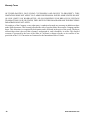
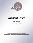
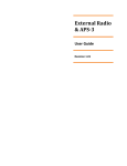
AW400Rx
User Manual
Version 1.0
Last Revised April 22, 2009
All contents in this manual are copyrighted by ArWest Communications.
All rights reserved.The information contained herein may not be used, accessed, copied,
stored, displayed, sold, modified, published, or distributed, or otherwise reproduced without
express written consent from ArWest Communications.
www.arwestcom.com
TABLE OF CONTENTS
Preface . . . . . . . . . . . . . . . . . . . . . . . . . . . . . . . . . . . . . . . . . . . . . . . . . . . . . . . . .5
Terms and Conditions. . . . . . . . . . . . . . . . . . . . . . . . . . . . . . . . . . . . . . . . . . . . . . . . . . . . . . . . 5
Regulatory Information . . . . . . . . . . . . . . . . . . . . . . . . . . . . . . . . . . . . . . . . . . . . . . . . . . . . . . 6
FCC Class A Compliance . . . . . . . . . . . . . . . . . . . . . . . . . . . . . . . . . . . . . . . . . . . . . . . . . 6
Canadian Emissions Labeling Requirements . . . . . . . . . . . . . . . . . . . . . . . . . . . . . . . . . . 7
WEEE Directive . . . . . . . . . . . . . . . . . . . . . . . . . . . . . . . . . . . . . . . . . . . . . . . . . . . . . . . . 7
Glossary . . . . . . . . . . . . . . . . . . . . . . . . . . . . . . . . . . . . . . . . . . . . . . . . . . . . . . . . . . . . . . . . . . 9
Related Information . . . . . . . . . . . . . . . . . . . . . . . . . . . . . . . . . . . . . . . . . . . . . . . . . . . . . . . . 10
Technical Assistance . . . . . . . . . . . . . . . . . . . . . . . . . . . . . . . . . . . . . . . . . . . . . . . . . . . 10
Return Material Authorization . . . . . . . . . . . . . . . . . . . . . . . . . . . . . . . . . . . . . . . . . . . . 10
Chapter 1. Product Features. . . . . . . . . . . . . . . . . . . . . . . . . . . . . . . . . . . . . . .11
1.1. Introduction . . . . . . . . . . . . . . . . . . . . . . . . . . . . . . . . . . . . . . . . . . . . . . . . . . . . . . . . . . . 11
1.1.1. Operating at Ultra High Frequency Band . . . . . . . . . . . . . . . . . . . . . . . . . . . . . . . 12
1.1.2. Modulation Technique . . . . . . . . . . . . . . . . . . . . . . . . . . . . . . . . . . . . . . . . . . . . . 12
1.1.3. Media Access Control (MAC) . . . . . . . . . . . . . . . . . . . . . . . . . . . . . . . . . . . . . . . 13
1.1.4. Operating Modes . . . . . . . . . . . . . . . . . . . . . . . . . . . . . . . . . . . . . . . . . . . . . . . . . . 13
1.1.5. Management Tools . . . . . . . . . . . . . . . . . . . . . . . . . . . . . . . . . . . . . . . . . . . . . . . . 13
1.1.6. Security . . . . . . . . . . . . . . . . . . . . . . . . . . . . . . . . . . . . . . . . . . . . . . . . . . . . . . . . . 14
Chapter 2. General Description . . . . . . . . . . . . . . . . . . . . . . . . . . . . . . . . . . . .15
2.1. Physical Interfaces . . . . . . . . . . . . . . . . . . . . . . . . . . . . . . . . . . . . . . . . . . . . . . . . . . . . . . 15
2.1.1. Serial Data Interface . . . . . . . . . . . . . . . . . . . . . . . . . . . . . . . . . . . . . . . . . . . . . . . 15
2.1.2. Power Interface . . . . . . . . . . . . . . . . . . . . . . . . . . . . . . . . . . . . . . . . . . . . . . . . . . . 15
2.1.3. Power Consumption . . . . . . . . . . . . . . . . . . . . . . . . . . . . . . . . . . . . . . . . . . . . . . . 15
2.1.4. Antennas . . . . . . . . . . . . . . . . . . . . . . . . . . . . . . . . . . . . . . . . . . . . . . . . . . . . . . . . 15
Chapter 3. Command Line Interface . . . . . . . . . . . . . . . . . . . . . . . . . . . . . . . .17
3.1. Command Line Interface Convention . . . . . . . . . . . . . . . . . . . . . . . . . . . . . . . . . . . . . . . 18
3.1.1. Software Switching to Command Mode . . . . . . . . . . . . . . . . . . . . . . . . . . . . . . . . 18
3.1.2. Switching to Data Mode . . . . . . . . . . . . . . . . . . . . . . . . . . . . . . . . . . . . . . . . . . . . 19
3.2. Networking Commands . . . . . . . . . . . . . . . . . . . . . . . . . . . . . . . . . . . . . . . . . . . . . . . . . . 20
3.2.1. CONNECT . . . . . . . . . . . . . . . . . . . . . . . . . . . . . . . . . . . . . . . . . . . . . . . . . . . . . . 20
3.2.2. LINK . . . . . . . . . . . . . . . . . . . . . . . . . . . . . . . . . . . . . . . . . . . . . . . . . . . . . . . . . . . 20
3.3. Serial Interfacing Commands . . . . . . . . . . . . . . . . . . . . . . . . . . . . . . . . . . . . . . . . . . . . . 21
www.arwestcom.com
3
3.3.1. DPORT . . . . . . . . . . . . . . . . . . . . . . . . . . . . . . . . . . . . . . . . . . . . . . . . . . . . . . . . . 21
3.3.2. MPORT . . . . . . . . . . . . . . . . . . . . . . . . . . . . . . . . . . . . . . . . . . . . . . . . . . . . . . . . 22
3.4. Special Commands . . . . . . . . . . . . . . . . . . . . . . . . . . . . . . . . . . . . . . . . . . . . . . . . . . . . .
3.4.1. ALARM . . . . . . . . . . . . . . . . . . . . . . . . . . . . . . . . . . . . . . . . . . . . . . . . . . . . . . . .
3.4.2. BOOT . . . . . . . . . . . . . . . . . . . . . . . . . . . . . . . . . . . . . . . . . . . . . . . . . . . . . . . . . .
3.4.3. HELP . . . . . . . . . . . . . . . . . . . . . . . . . . . . . . . . . . . . . . . . . . . . . . . . . . . . . . . . . .
3.4.4. SAVE . . . . . . . . . . . . . . . . . . . . . . . . . . . . . . . . . . . . . . . . . . . . . . . . . . . . . . . . . .
3.4.5. SLEEP . . . . . . . . . . . . . . . . . . . . . . . . . . . . . . . . . . . . . . . . . . . . . . . . . . . . . . . . .
22
22
23
23
23
23
3.5. Diagnostics and Identification Commands . . . . . . . . . . . . . . . . . . . . . . . . . . . . . . . . . . 24
3.5.1. INFO. . . . . . . . . . . . . . . . . . . . . . . . . . . . . . . . . . . . . . . . . . . . . . . . . . . . . . . . . . . 24
3.5.2. STATE . . . . . . . . . . . . . . . . . . . . . . . . . . . . . . . . . . . . . . . . . . . . . . . . . . . . . . . . . 25
Appendix A. Technical Specifications . . . . . . . . . . . . . . . . . . . . . . . . . . . . . . 27
A.1. Technical Specifications . . . . . . . . . . . . . . . . . . . . . . . . . . . . . . . . . . . . . . . . . . . . . . . .
A.1.1. Radio receiver . . . . . . . . . . . . . . . . . . . . . . . . . . . . . . . . . . . . . . . . . . . . . . . . . . .
A.1.2. Modem. . . . . . . . . . . . . . . . . . . . . . . . . . . . . . . . . . . . . . . . . . . . . . . . . . . . . . . . .
A.1.3. Compliance . . . . . . . . . . . . . . . . . . . . . . . . . . . . . . . . . . . . . . . . . . . . . . . . . . . . .
A.1.4. General. . . . . . . . . . . . . . . . . . . . . . . . . . . . . . . . . . . . . . . . . . . . . . . . . . . . . . . . .
A.1.5. Mechanical Properties For End-product . . . . . . . . . . . . . . . . . . . . . . . . . . . . . . .
27
27
28
28
29
30
A.2. External Connectors. . . . . . . . . . . . . . . . . . . . . . . . . . . . . . . . . . . . . . . . . . . . . . . . . . . . 30
A.2.1. Antenna Connector . . . . . . . . . . . . . . . . . . . . . . . . . . . . . . . . . . . . . . . . . . . . . . . 30
A.2.2. User Ports’ Connector . . . . . . . . . . . . . . . . . . . . . . . . . . . . . . . . . . . . . . . . . . . . . 31
Appendix B. Safety Warnings . . . . . . . . . . . . . . . . . . . . . . . . . . . . . . . . . . . . . 33
B.1. General Warnings. . . . . . . . . . . . . . . . . . . . . . . . . . . . . . . . . . . . . . . . . . . . . . . . . . . . . . 34
Appendix C. UHF Radio Usage . . . . . . . . . . . . . . . . . . . . . . . . . . . . . . . . . . . . 35
Appendix D. Warranty Terms . . . . . . . . . . . . . . . . . . . . . . . . . . . . . . . . . . . . . 37
4
www.arwestcom.com
PREFACE
Thank you for purchasing this product. The materials available in this Manual (the “Manual”) have been
prepared by ArWest Communications (“ArWest Communications”) for owners of ArWest
Communications products. It is designed to assist owners with the use of the AW400Rx and its use is
subject to these terms and conditions (the “Terms and Conditions”).
Note: Please read these Terms and Conditions carefully.
Terms and Conditions
COPYRIGHT – All information contained in this Manual is the intellectual property of, and copyrighted
material of ArWest Communications. All rights are reserved. You may not use, access, copy, store,
display, create derivative works of, sell, modify, publish, distribute, or allow any third party access to, any
graphics, content, information or data in this Manual without ArWest Communications’ express written
consent and may only use such information for the care and operation of your AW400Rx. The
information and data in this Manual are a valuable asset of ArWest Communications and are developed
by the expenditure of considerable work, time and money, and are the result of original selection,
coordination and arrangement by ArWest Communications.
TRADEMARKS – AW400Rx, ArWest Communications® are trademarks or registered trademarks of
ArWest Communications. Windows® is a registered trademark of Microsoft Corporation. Product and
company names mentioned herein may be trademarks of their respective owners.
DISCLAIMER OF WARRANTY – EXCEPT FOR ANY WARRANTIES IN THIS MANUAL OR A
WARRANTY CARD ACCOMPANYING THE PRODUCT, THIS MANUAL AND THE AW400Rx
A R E P ROV I D E D “A S - I S .” T H E R E A R E N O OT H E R WA R R A N T I E S . A RW E S T
COMMUNICATIONS DISCLAIMS ANY IMPLIED WARRANTY OF MERCHANTABILITY OR
FITNESS FOR ANY PARTICULAR USE OR PURPOSE. ARWEST COMMUNICATIONS AND ITS
DISTRIBUTORS SHALL NOT BE LIABLE FOR TECHNICAL OR EDITORIAL ERRORS OR
OMISSIONS CONTAINED HEREIN; NOR FOR INCIDENTAL OR CONSEQUENTIAL DAMAGES
RESULTING FROM THE FURNISHING, PERFORMANCE OR USE OF THIS MATERIAL OR THE
AW400Rx. SUCH DISCLAIMED DAMAGES INCLUDE BUT ARE NOT LIMITED TO LOSS OF
TIME, LOSS OR DESTRUCTION OF DATA, LOSS OF PROFIT, SAVINGS OR REVENUE, OR
LOSS OF THE PRODUCT'S USE. IN ADDITION, ARWEST COMMUNICATIONS IS NOT
RESPONSIBLE OR LIABLE FOR DAMAGES OR COSTS INCURRED IN CONNECTION WITH
O B TA I N I N G S U B S T I T U T E P RO D U C T S O R S O F T WA R E , C L A I M S B Y OT H E R S ,
INCONVENIENCE, OR ANY OTHER COSTS. IN ANY EVENT, ARWEST COMMUNICATIONS
SHALL HAVE NO LIABILITY FOR DAMAGES OR OTHERWISE TO YOU OR ANY OTHER
PERSON OR ENTITY IN EXCESS OF THE PURCHASE PRICE FOR THE AW400Rx.
www.arwestcom.com
5
Preface
Regulatory Information
FCC Class A Compliance
LICENSE AGREEMENT – Use of any computer programs or software supplied by ArWest
Communications or downloaded from a ArWest Communications website (the “Software”) in connection
with the AW400Rx constitutes acceptance of these Terms and Conditions in this Manual and an
agreement to abide by these Terms and Conditions. The user is granted a personal, non-exclusive, nontransferable license to use such Software under the terms stated herein and in any case only with a single
AW400Rx or single computer. You may not assign or transfer the Software or this license without the
express written consent of ArWest Communications. This license is effective until terminated. You may
terminate the license at any time by destroying the Software and Manual. ArWest Communications may
terminate the license if you fail to comply with any of the Terms or Conditions. You agree to destroy the
Software and manual upon termination of your use of the AW400Rx. All ownership, copyright and other
intellectual property rights in and to the Software belong to ArWest Communications. If these license
terms are not acceptable, return any unused software and manual.
CONFIDENTIALITY – This Manual, its contents and the Software (collectively, the “Confidential
Information”) are the confidential and proprietary information of ArWest Communications. You agree to
treat ArWest Communications' Confidential Information with a degree of care no less stringent that the
degree of care you would use in safeguarding your own most valuable trade secrets. Nothing in this
paragraph shall restrict you from disclosing Confidential Information to your employees as may be
necessary or appropriate to operate or care for the AW400Rx. Such employees must also keep the
Confidentiality Information confidential. In the event you become legally compelled to disclose any of
the Confidential Information, you shall give ArWest Communications immediate notice so that it may
seek a protective order or other appropriate remedy.
WEBSITE; OTHER STATEMENTS – No statement contained at the ArWest Communications website
(or any other website) or in any other advertisements or ArWest Communications literature or made by an
employee or independent contractor of ArWest Communications modifies these Terms and Conditions
(including the Software license, warranty and limitation of liability).
SAFETY – Improper use of the AW400Rx can lead to injury to persons or property and/or malfunction
of the product. The AW400Rx should only be repaired by authorized ArWest Communications warranty
service centers. Users should review and heed the safety warnings in Chapter B on page 33.
MISCELLANEOUS – The above Terms and Conditions may be amended, modified, superseded, or
canceled, at any time by ArWest Communications. The above Terms and Conditions will be governed by,
and construed in accordance with, the laws of the State of California, without reference to conflict of
laws.
Regulatory Information
The following sections provide information on this product's compliance with government regulations.
FCC Class A Compliance
This equipment has been tested and found to comply with the limits for a Class A digital device, pursuant
to part 15 of the FCC Rules. These limits are designed to provide reasonable protection against harmful
interference when the equipment is operated in a commercial environment. This equipment generates,
6
www.arwestcom.com
Preface
Regulatory Information
Canadian Emissions Labeling Requirements
uses, and can radiate radio frequency energy and, if not installed and used in accordance with the
instruction manual, may cause harmful interference to radio communications. Operation of this
equipment in a residential area is likely to cause harmful interference in which case the user will be
required to correct the interference at his own expense.
Note: Any changes or modifications to the equipment not expressly approved by the party responsible for
compliance could void your authority to operate such equipment.
Canadian Emissions Labeling Requirements
This Class A digital apparatus meets all requirements of the Canadian Interference-Causing Equipment
Regulations.
Cet appareil numérique de la classe A respecte toutes les exigences du Réglement sur le matériel
brouilleur du Canada.
WEEE Directive
The following information is for EU-member states only:
The use of the symbol indicates that this product may not be treated as household waste. By ensuring this
product is disposed of correctly, you will help prevent potential negative consequences for the
environment and human health, which could otherwise be caused by inappropriate waste handling of this
product. For more detailed information about the take-back and recycling of this product, please contact
your supplier where you purchased the product or consult.
www.arwestcom.com
7
DECLARATION of CONFORMITY
According to ISO/IEC Guide 22 and EN45014
Manufacturer’s Name:
Manufacturer’s Address:
ArWest Communications Corporation
1731 Technology Drive
San Jose, CA 95110
USA
declares, that the products
Product Name:
AW400Tx OEM transceiver and AW400Rx OEM receiver
Product Number:
01-00012-200, 01-00011-110
Product Options:
All
conforms to the following Product Specification:
EMC:
Directive 89/336/EEC
EN 300 113 -1, EN 300 113 - 2
EN 301 489 -1, EN 301 489 - 5
Supplementary Information:
The product herewith complies with the essential requirements of the directive 1999/5/EC of the European
Parliament and of the Council of 9 March 1999 on radio equipment and telecommunications terminal
equipment (R&TTE) and the mutual recognition of their conformity and carries the CE marking accordingly
1) These products were tested in a typical configuration with ArWest Communications Corporation products
2) AW400Rx is identical to AW400Tx, but without transmitting part
This Declaration of Conformity is based on the following documents:
Doc No
3157867MPK-001
3157867MPK-001
3157867MPK-002
3157867MPK-002
Type of Product
Test Specification
AW400Tx/AW400Rx EN 300 113-2
AW400Tx/AW400Rx EN 300 113-1
AW400Tx/AW400Rx EN 301 489-1
AW400Tx/AW400Rx EN 301 489-5
San Jose, March 30, 2009
Laboratory / Date of issue
Intertek / Menlo Park 24.12.2008
Intertek / Menlo Park 24.12.2008
Intertek / Menlo Park 31.08.2008
Intertek / Menlo Park 31.08.2008
Vladimir Zhukov, Product Regulations Manager
USA contact: ArWest Communications Corporation, 1731 Technology Drive, San Jose, CA 95110. Phone: +1 408 452 7719
Revision 1.2
Preface
Glossary
WEEE Directive
Glossary
µC
AGC
ALC
AWGN
BER
BERT
CLI
CMOS
CRC
CTS
CW
DBPSK
DC
DCD
DQPSK
DSP
DSR
DTE
DTR
ETSI
FCC
FEC
FIFO
FSK
GMSK
GUI
HPA
I/O
IF
LED
LLC
LNA
MAC
MSK
MTBF
MTTR
PA
PCB
PDA
PLL
PMP
PSK
PTP
www.arwestcom.com
Micro Controller
Automatic Gain Control
Automatic Output Power Level Control
Additive White Gaussian Noise
Bit Error Rate
Bit Error Rate Test
Command Line Interface
Complementary Metal-Oxide Semiconductor
Cyclic Redundancy Code
Clear To Send
Continues Wave
Differential Binary Phase Shift Keying
Direct Current
Data Carrier Detect
Differential Quadrature Phase Shift Keying
Digital Signal Processing
Data Set Ready
Data Terminal Equipment
Data Terminal Ready
European Telecommunications Standardization Institute
Federal Communications Commission
Forward Error Correction
First-Input-First-Output
Frequency Shift Keying
Minimum Shift Keying with Gaussian filtering
Graphical User Interface
High Power Amplifier
Input/Output
Intermediate Frequency
Light Emitting Diode
Logic Link Control
Low Noise Amplifier
Media Access Control
Minimum-shift keying
Mean Time Between Failures
Mean Time To Repair
Power Amplifier
Printed Circuit Board
Personal Digital Assistant
Phase-Lock Loop
Point-to-Multipoint
Phase Shift Keying
Point-to-Point
9
Preface
Related Information
Technical Assistance
QAM
QPSK
RF
RSSI
RTK
RTS
RX
SCADA
SRAM
TDD
TDM
TDMA
TPC
TPO
TTL
TX
UART
VHF
UIM
VSWR
FIRMWARE
SOFTWARE
Quadrature Amplitude Modulation
Quadrature Phase Shift Keying
Radio Frequency
Received Signal Strength Indication
Real-time Kinematics
Request To Send
Receive(r)
Supervisor Control and Data Acquisition
Static Random Access Memory
Time Division Duplex
Time Division Multiplexing
Time Division Multiple Access
Turbo Product Codes
Transmitter Output Power
Transistor-Transistor-Logic
Transmit(ter)
Universal Asynchronous Receiver/Transmitter
Ultra High Frequency (300-3000 MHz)
User Identify Module
Voltage Standing Wave Ratio
A software program or a set of instructions embedded on a hardware device
Computer program for communication with a hardware device
Related Information
Technical Assistance
If you have a problem and cannot find the information you need in the product documentation, contact
your local dealer. Alternatively, request technical support using the ArWest Communications World Wide
Web site at: www.arwestcom.com
Return Material Authorization
Initially, the customer contacts support to r e p or t a p r o b l e m . P l e a s e r e f e r t o s u p p o r t :
[email protected]
If support determines the problem cannot be resolved over e-mail/internet, it will authorize the return of
the unit for repair or replacement, depending on the nature of the problem.
10
www.arwestcom.com
Chapter 1
PRODUCT FEATURES
1.1. Introduction
AW400Rx DSP based integrated UHF receiver is the single board OEM wireless receiver intended for
SCADA, outdoor telemetry applications and receiving of differential corrections and additional
information by terrestrial radio channels between two GNSS receivers.
Figure 1-1. AW400Rx
The UHF receiver is capable of receiving RF signals through a 50 Ohm impedance external antenna port.
AW400Rx delivers a reliable radio link at up to 38.4 kbps over the air for the 25 kHz channel spacing, 30
kpbs for 20 kHz, 19.2 kbps for 12.5 kHz, and 9.6 kbps for 6.25 kHz. The module requires a regulated DC
voltage power supply 3.6 V ± 5%.
The delivered product is a wireless system, which includes:
• AW400Rx – UHF Radio receiver;
• AWLaunch – Windows based Unit Configuration and Maintenance Software Application running
on a IBM PC compatible computer and connecting to the device over RS-232 interface or USBto-Serial adapter.
The setting can be done through the built-in Command Line interface (CLI), or through the configuration
and maintenance application software running either on PC – AWLaunch.
The diagnostic feature of the AW400Rx system provides the information to monitor and maintain user’s
communications link. The output transmit power, receive signal strength (RSSI), antenna/feedline
condition, and data decode performance are transmitted online without application interruption.
The product is designed for maximum performance and reliability even in the harshest environments.
Plug and play at its best, robust, withstanding the most adverse of conditions.
www.arwestcom.com
11
Product Features
Introduction
Operating at Ultra High Frequency Band
1.1.1. Operating at Ultra High Frequency Band
AW400Rx operates in UHF frequency band covering both licensed and unlicensed frequencies. The
following are its key benefits:
1. Operating in UHF frequency band will provide a non-line of sight connection.
2. Single radio system covers the whole UHF frequency band from 406 to 470 MHz;
3. User selectable channel spacing (25 kHz, 20 kHz, 12.5 kHz or 6.25 kHz);
1.1.2. Modulation Technique
The design is based on high-level modulation techniques which include:
Modulation/ Channel Spacing
6.25 kHz
12.5 kHz
20 kHz
25 kHz
DBPSK – Differential Binary Phase Shift Keying
2.4 kbps
4.8 kbps
7.5 kbps
9.6 kbps
DQPSK – Differential Quadrature Phase Shift Keying
4.8 kbps
9.6 kbps
15 kbps
19.2 kbps
D8PSK – Eight Phase Shift Keying
7.2 kbps
14.4 kbps 22.5kbps 28.8 kbps
D16QAM – Sixteen Quadrature Amplitude Modulation 9.6 kbps
19.2 kbps 30 kbps
38.4 kbps
GMSK – Minimal Shift Keying with Gaussian Filtering 2.4 kbps
4.8 kbps
7.5 kbps
9.6 kbps
4FSK- Four Level Frequency Shift Keying
9.6 kbps
15.0 kbps 19.2 kbps
N/A1
1. N/A – Not Applicable
12
www.arwestcom.com
Product Features
Introduction
Media Access Control (MAC)
1.1.3. Media Access Control (MAC)
The following Media Access protocols are available for AW400Rx modem:
1. Simplex protocols (Simplex Base, Simplex Remote, and Repeater) are developed primarily for
GNSS applications.
2. Sleep mode is an investment provided by MAC sub-layer that provides additional power saving.
The wakeup from Sleep mode is user selectable either by an internal real-time clock, or by an
external controller through the data interface control lines (RTS or DTR), or by SLEEP input line
(CMOS/TTL compatible input lines).
1.1.4. Operating Modes
The operating modes for AW400Rx can be set through the CLI, and/or through AWLaunch. The
following operating mode are available for AW400Rx:
• The sleep mode has automatic transmitter activation by an internal real-time clock, or by an
external controller through the data interface control lines (RTS and DTR), or by the triggering of
the external Sense Inputs.
1.1.5. Management Tools
The built-in management tools along with AWLaunch (configuration and monitoring software
application) will provide the following benefits:
1. Easy user’s interface for system configuration and monitoring using well developed CLI or intuitive GUI.
2. An ability to monitor status, alarms and radio performance through the intuitive GUI.
3. Software upgrades and improvements can be downloaded from AWLaunch to the units connected
with PC/PDA.
www.arwestcom.com
13
Product Features
Introduction
Security
1.1.6. Security
The system provides wireless media access protection as well as data encryption. The following are its
key features and benefits:
1. The Key Sequence generated by Pseudo-random generator scrambles the fully formatted frame
(including Frame’s CRC). This provides the wireless media access protection.
2. User selectable Frequency Hopping Pattern provides another level of the wireless media access
protection.
At the same time it allows operators to increase the number of links deployed in the same location.
14
www.arwestcom.com
Chapter 2
GENERAL DESCRIPTION
2.1. Physical Interfaces
2.1.1. Serial Data Interface
The serial asynchronous interface allows connection to external serial devices. It is shared between user
data and unit’s command/status information. All commonly supported baud rates, parity and bit
configurations are available up to 115.2 kbps.
2.1.2. Power Interface
The power interface allows connection to an unregulated DC power source. The DC power source (thirdparty or user supplied) must provide DC power of 3.6V±5% DC.
The standalone unit’s RF interface is a 50-ohm impedance matched standard MMCX connector as
required by regulation.
2.1.3. Power Consumption
Power consumption of the UHF radio receiver is less than 1000mW (refer to Table 2-1 for details).
Table 2-1. Power Consumption
Operating Mode / Description
Consumption
Sleep Mode
300 mW
Standby Mode, ordered by SLEEP input pin
500 µW
2.1.4. Antennas
Antenna type depends on the site requirements, and may be directional or omni-directional.
www.arwestcom.com
15
General Description
Physical Interfaces
Antennas
16
www.arwestcom.com
Chapter 3
COMMAND LINE INTERFACE
The built-in user-friendly Command Line Interface (CLI) allows user to perform a full configuration of
the unit and read the statistics and alarm status. It is the most powerful tool to configure the unit. It makes
changes to all possible settings that system will not be able to determine automatically.
The CLI commands allow user to configure and reconfigure the unit’s settings. The user configuration
parameters that could be changed through the CLI are:
• Data Port Settings
- Baud Rate
- Data Bits (8, 7)
- Parity (Odd, Even, None)
- Flow control (None or RTS/CTS)
• Alarm Settings
• Radio Operation Modes
• Sleep modes
- On/Off
- Activate by internal real-time clock
- Activate through RTS/CTS lines
- Activate by external sense lines
- Activate by any combination of the parameters mentioned before
Note: The unit’s configuration that is set or modified through the CLI will be lost after unit’s reboot, unless the
saving operation is used to store a new setting in the unit’s configuration file.
The CLI commands also provide filing operations, which include:
• Downloading
- Unit’s Configuration files
- Software Images
• Uploading Unit’s Configuration files
• Saving into the configuration files the configuration parameters modified through the CLI.
www.arwestcom.com
17
Command Line Interface
Command Line Interface Convention
Software Switching to Command Mode
3.1. Command Line Interface Convention
The following convention is implemented in AW400Rx Command Line Interface (CLI):
• The Carriage Return/Line Feed (CR/LF, 0x0D/0x0A) is a command delimiter.
• The Carriage Return/Line Feed (CR/LF, 0x0D/0x0A) is a reply delimiter followed by the “CLI>”
prompt if Echo option is On.
• The Carriage Return/Line Feed (CR/LF, 0x0D/0x0A) is a reply delimiter if Echo option is Off
(default option).
• The 2-digit number followed by “@” in the unit’s reply indicates the error code (refer to Table 31 for description), if Echo Off is selected, otherwise the error message is displayed.
• A successfully performed command is replied by @00 code, if Echo Off is selected, otherwise the
set value is replied.
• A command with the certain [Parameter Name] and blank [Parameter List] displays the current
settings for a given parameter.
• To set the mode ordered by CLI commands as permanent User Setting (the setting automatically
selected for the boot-up unit) the SAVE command must be asserted.
• [/?] orders to show the help information for the given command.
• Commands are not key sensitive; small, none capital characters can be used to enter CLI
commands.
Table 3-1. Command Line Interface Error Codes
Error Code
Short Description
0x01
Command Syntax Error. A command followed by “/?” displays a command usage.
0x02
The parameter has a format error. A command with the certain [Parameter Name]
followed by “/?” displays the format and range of the variable.
0x03
The parameter is out of allowed range. A command with the certain [Parameter
Name] followed by “/?” displays the format and range of the variable.
0x04
The command is not valid for specific radio model. To display the list of available
commands, the HELP command must be used (see “Software Switching to
Command Mode” ).
0x05
Unspecified Error
3.1.1. Software Switching to Command Mode
Software Switching to Maintenance Mode can be utilized if Data/Maintenance Port (DP/MP) control line
is set to High Z (or 3.3v) level. To switch to Maintenance mode the special byte-sequences with special
meanings are used:
• Escape-Sequence: “+++” with 20 ms guard time before and after the command characters
• Escape-Acknowledge: “@00<CR><LF>” 20 ms toggling on CTS control line needed to
acknowledge switching from Data to Maintenance mode and vice versa. In Maintenance mode,
the unit’s serial port must keep CTS line always active.
18
www.arwestcom.com
Command Line Interface
Command Line Interface Convention
Switching to Data Mode
Happy Flow
1. In data-mode the unit starts looking for the Escape-sequence if there is no data from DTE for
more than 20 ms (Start Guard Time).
2. If the unit detects the Escape-Sequence:
• The transmitter continues sending over the air the data received from DTE before EscapeSequence and buffers the data from DTE;
• The Receiver immediately stops forwarding to DTE the data received over the air and buffers it
instead.
3. The radio unit waits for 20 ms and then sends Escape-Acknowledge to DTE if there is no data
from DTE during 20 ms of Stop Guard Time.
4. The unit goes to Maintenance mode and discards Escape-Sequence from input buffer. The modem
is immediately ready to receive commands. At the same time it continues buffering the data
received over the air since step 2.
Escape-Sequence in Data
During its waiting in step 3, the unit receives data from DTE:
• The unit sends buffered Escape-Sequence from DTE to the air;
• The unit sends all buffered data received from the air since step 2 to DTE and stays in data-mode
(i.e. transmits data received from DTE over the air – including the just received, unexpected, data
and forwards data received over the air to DTE.)
3.1.2. Switching to Data Mode
• DTE sends the CLI command „DATAMODE<CR><LF>“to the unit.
• Unit answers with Escape-Acknowledge („@00<CR><LF>“) and immediately goes to datamode,
so that the DTE can start sending data as soon as the Escape-Acknowledge has been received.
• If no valid CLI commands received from DTE within 1 minute, the unit will automatically switch
back to data-mode.
Note: The data received over the air could be lost due to Rx buffer overflow if the unit stays in Maintenance
mode longer then 15 second.
www.arwestcom.com
19
Command Line Interface
Networking Commands
CONNECT
3.2. Networking Commands
3.2.1. CONNECT
To connect the radio unit through the local maintenance serial port or to establish the link with the remote
unit in the Point-to-Multipoint network, the CONNECT command must be used.
CONNECT [Unit_Numb] [/?]
Where the Unit_Numb is an assigned decimal number for the unit to be connected. To get the complete
unit list, the CONNECT command must be used with no parameter. The list of units in the Point-to-Point
link with the connection established with remote unit is shown in Figure 3-1:
Unit
Serial Number
BS
003578659922
1
003574459923
Connect
C
Figure 3-1. Connection List
To disconnect from the remote unit and connect to the local unit, the parameter (Unit_Numb) must be
equal to 0x00.
3.2.2. LINK
The LINK command is responsible for configuring radio’s operation mode. It has six parameters listed
below.
LINK [Parameter Name] [Parameters List] [/?]
Parameter Name
20
Parameter List
CHAN
Selects the Channel Number: CN = 1 to 32.
Each Channel is defined by three parameters: Carrier Frequency, Channel
Spacing and Allowed Output Power level.
CN = 0 is reserved to set up the Frequency Automatic scanning mode.
The LINK CHAN 0 command also forces the radio modem to continue scanning
starting from the channel currently selected by automatic scanning algorithm.
In Automatic scanning mode, to check the channel currently used or scanned,
the STATE command must be used
FEC
0 – Disable Forward Error Correction, a default setting (see note below)
1 – Enable Forward Error Correction (see note below)
FHOP
(1 – 32) – Frequency Hoping Pattern number LINK FHOP command can be processed
only if the Channel Map (up to 32 channels) is defined by AWLaunch or by MAP
command.
PROT
1 – “Simplex Receiver” a default setting (see note below)
7 – “TRMB Receiver” (used with GMSK modulation)
12 – “Transparent w/EOT” Receiver (used with GMSK and 4FSK)
14 – “STL Receiver” (used with 4FSK modulation)
SCRAM
0 – No Scrambling (a default setting)
(1 – 255) – Seed for Pseudo-Random Sequence Generator
www.arwestcom.com
Command Line Interface
Serial Interfacing Commands
DPORT
Note: LINK FHOP and LINK CHAN commands can be processed only if Frequency Map is defined.
Auto-scanning may not start automatically, only when scanning requested via CLI command (see
LINK CHAN 0 and STATE commands).
The frequency defined by CHAN parameter is not valid if Frequency Hoping mode is selected.
The radio link with GMSK and 4FSK modulations are used by Non-ArWest protocols only.
Enabling FEC via LINK FEC command provides different options for different protocols:
- Enables Read-Solomon encoding for frame’s header used by ArWest proprietary protocols
- Enables Hamming encoding for Trimble and Pacific Crest compatible protocols
- Enables Trellis encoding for Satel compatible protocol
For ArWest proprietary protocols, the Read-Solomon FEC encoding is always applied to data
payload.
LINK ADDR and LINK CLKCORR commands are not recommended for using on site of End Users.
3.3. Serial Interfacing Commands
3.3.1. DPORT
The DPORT is an object that responsible for data port interface configurations like Bit Rate, Flow
Control, etc.
DPORT [Parameter Name] [Parameters List] [/?]
Parameter Name
Parameter List
RATE
0 – Maintenance Port baud rate, a default setting
1 – 1200 baud
2 – 2400 baud
3 – 4800 baud
4 – 9600 baud
5 – 14400 baud
6 – 19200 baud
7 – 38400 baud
8 – 57600 baud
9 – 115200 baud, a default setting
BITS
Set number of bits in one byte (8 or 7)
8 is a default setting
PARITY
0 – None, a default setting
1 – Odd
2 – Even
FLOW
0 – None, a default setting
1 – Not used
2 – HW (RTS/CTS)
www.arwestcom.com
21
Command Line Interface
Special Commands
MPORT
3.3.2. MPORT
The MPORT is an object that responsible for maintenance serial port interface configurations such as data
rate and number of bits in a byte.
MPORT [Parameter Name] [Parameters List] [/?]
Parameter Name
RATE
Parameter List
0 – Auto.
1 – 1200 baud
2 – 2400 baud
3 – 4800 baud
4 – 9600 baud
5 – 14400 baud
6 – 19200 baud
7 – 38400 baud
8 – 57600 baud
9 – 115200 baud, a default setting
Note: ArWest radio modem’s does not support data flow and parity on the maintenance serial port.
MPORT operates using 8 bits in one byte fixed (not configurable).
The radio modem with none-dedicated maintenance serial port must keep CTS line always active in
MPORT mode (DP/MP is low).
3.4. Special Commands
3.4.1. ALARM
The ALARM command is intended to set up the alarm indication mode and alarm control lines’ behavior.
ALARM [Parameter Name] [Parameters List] [/?]
Parameter Name
Parameter List
TTL1
0 – TTL_OUT1 = logic “1”
1 – TTL_OUT1 = TTL_IN, received from remote unit (default settings)
TTL2
0 – TTL_OUT2 = logic “1”
1 – TTL_OUT2 = TTL_IN2, received from remote unit (default settings)
2 – TTL_OUT2 = SYNC Loss
3 – TTL_OUT2 = BER > BERTH or SYNC Loss
BERTH
1– BER Threshold >10 –3 (default threshold level for BER)
2 – BER Threshold BER >10 –2
The Alarm LED must indicate the SYNC Loss and BER exceeding the defined threshold.
Note: The BERTH 1 / 2 is optional for TTL2 = 3 condition, otherwise the BERT alarm is off
22
www.arwestcom.com
Command Line Interface
Special Commands
BOOT
3.4.2. BOOT
The BOOT command is intended to reboot the unit using selected user settings. Two options are
available, to use the default user settings defined by dealer or to use the settings defined by end-user
BOOT [Parameter Name] [Parameters List] [/?]
Parameter Name
CFG
Parameter List
0 – selects the default user settings
1 – selects user modified settings
The BOOT command with no parameters selects the user settings defined by the prior “parameterized”
BOOT commands.
3.4.3. HELP
The HELP command types the list of all available commands:
HELP
– Display this usage
BOOT
– Reboot the unit
LINK
– RF Link Operation Mode
DPORT
– Data Port Configuration
MPORT
– Maintenance Port Configuration
ALARM
– Alarm Indication and Alarm Control Configuration
SLEEP
– Sleep Mode Configuration
CONNECT – Connect to Specified Unit
STATE
– Display Status and Statistics
SAVE
– Save Current Configuration into Configuration File
INFO
– Display Product ID along with Hardware/Software Versions
DATAMODE – Exit Maintenance Mode
[COMMAND] /? – Display Command Usage
3.4.4. SAVE
The SAVE command is intended to store the unit’s currently used configuration into the User
Configuration file. The configuration stored in the User Configuration file is activated by automatically
after unit’s reboot.
3.4.5. SLEEP
The SLEEP command determines the sleep mode parameters. The sleeping AW400Rx can be activated
by real-time CLK, DTR/RTS lines, and command received through TTL inputs. The user can select one,
two, or all three conditions.
www.arwestcom.com
23
Command Line Interface
Diagnostics and Identification Commands
INFO
SLEEP [Parameter Name] [Parameters List] [/?]
Parameter Name
Parameter List
CLK
0 – Do not activate by internal real-time clock
(1 – 255) – Activate by internal real-time clock after 100 to 25500 msec of sleeping
HW
0 – Do not activate through DTR/RTS lines
1 – Activate through DTR/RTS lines
TTL
0 – Do not activate by external sense lines
1 – Activate by external sense lines
GTS
0 – Disable Sleep mode (default)
(1 – 255) – Go to sleep mode if there is no activity in 10 to 2550 msec
3.5. Diagnostics and Identification Commands
3.5.1. INFO
The INFO command is used to retrieve the Radio ID along with its Hardware version, the loaded realtime software version/revision and BootLoader’s version/revision.
INFO [Parameter Name] [Parameters List] [/?]
Parameter Name
Parameter List
ID
Product ID
SN
Six bytes Serial Number (SN)
HW
1.0 – hardware version in numeric “Major.Minor” format
SW
Ver. 1.0 Rev. A – displays software’s version in numeric “Major.Minor” format and
revision in numeric format (range from 01 to 99) for engineering releases and alphabetic
format (A to Z) for manufacturing releases
BL
Ver. 1.0 Rev. A – displays BootLoader’s version in numeric “Major.Minor”format and
revision in numeric format (range from 01 to 99) for engineering releases and alphabetic
format (A to Z) for manufacturing releases
The INFO command without Parameter Name indicates all values:
AW400Rx UHF Radio Modem.
Product ID = 33
S/N = 000000 020303
Hardware = Ver. 1.0
Software = Ver. 1.8 Rev. 14
BootLoader = Ver. 2.0 Rev. 02
24
www.arwestcom.com
Command Line Interface
Diagnostics and Identification Commands
STATE
3.5.2. STATE
The STATE command is used to check the state of the wireless link, the unit in the link, and the alarm
control lines. To specify a radio unit (local or remote), the CONNECT command must be used in prior of
STATE command using.
STATE [Parameter Name] [Parameters List] [/?]
Parameter Name
Parameter List
RSSI
-52 to -116 dBm – Indicates the Receive Signal Strength in dBm
BER
1.0E-6 to 9.9E-3 – Indicates the BER level
FREQ
406.000000 to 470.000000 MHz – Displays the central frequency of the
operating channel
CHAN
1 to 9601 – Displays the selected or currently scanned frequency channel
TEMP
-30°C to 100°C – Displays the temperature inside of enclosure
SYNC
1 – Indicates the established link, 0 – if link is not established yet
The STATE command without Parameter Name indicates all values:
RSSI = -110 dBm
BER = < 2.3E-5
FREQ = 140.000000 MHz
CHAN = 10
TEMP = 70C
SYNC = 1
MODE = FIXED
Note: The indicated receive signal strength (RSSI) is equal to -147 dBm if there is no signal received from
transmitter.
www.arwestcom.com
25
Command Line Interface
Diagnostics and Identification Commands
STATE
26
www.arwestcom.com
Appendix A
TECHNICAL SPECIFICATIONS
AW400Rx DSP based integrated UHF receiver is the single board OEM wireless receiver intended for
SCADA, outdoor telemetry applications and transmission /receiving of differential corrections and
additional information by terrestrial radio channels between two GNSS receivers.
It supports the following modulation methods: GMSK, DBPSK, DQPSK, D8PSK, D16QAM.
A.1. Technical Specifications
A.1.1. Radio receiver
Table A-1. Radio receiver Specifications
Component
Details
Frequency Range
406-470 MHz
Channel Spacing
25/20/12.5/6.25 kHz
Carrier Frequency Stability
±1 ppm
Modulation
GMSK/4FSK/DBPSK/DQPSK/ D8PSK/D16QAM
Communication Mode
Simplex
Table A-2. Radio Receiver Specifications
Component
Details
Receiver Sensitivity for DBPSK
(BER 1x 10⁻⁴)
-113 dBm for 25 kHz Channel Spacing,
-113 dBm for 20 kHz Channel Spacing
-114 dBm for 12.5 kHz Channel Spacing,
-114 dBm for 6.25 kHz Channel Spacing
Receiver Sensitivity for DQPSK
(BER 1x 10⁻⁴)
-110 dBm for 25 kHz Channel Spacing
-110 dBm for 20 kHz Channel Spacing
-111 dBm for 12.5 kHz Channel Spacing
-111 dBm for 6.25 kHz Channel Spacing
Receiver Dynamic Range
-119 to -10dBm
www.arwestcom.com
27
A.1.2. Modem
Figure A-1. Modem Specifications
Component
Details
Interface
DSP UART (serial port)
Interface Connector
16-lead Connector
Data Speed of Serial Interface
9600 - 115200 bps
Data Rate of Radio Interface
(25 kHz Channel Spacing)
9600 bps – DBPSK/GMSK
19200 bps – DQPSK
28800 bps – D8PSK
38400 bps – D16QAM
Data Rate Radio Interface
(20 kHz Channel Spacing)
7500 bps – DBPSK/GMSK
15000 bps – DQPSK
22500 bps – D8PSK
30000 bps – D16QAM
Data Rate Radio Interface
(12.5 kHz Channel Spacing)
4800 bps – DBPSK/GMSK
9600 bps – DQPSK
14400 bps – D8PSK
19200 bps – D16QAM
Data Rate Radio Interface
(6.25 kHz Channel Spacing)
2400 bps – DBPSK
4800 bps – DQPSK
7200 bps – D8PSK
9600 bps – D16QAM
Forward Error Correction (FEC)
Reed-Solomon Error Correction
Data scrambling
Yes
A.1.3. Compliance
Component
Details
FCC
FCC Part 90
Industry Canada
RSS-210
ETSI
ETSI EN 300 113-2, ETSI EN 301 489-1, ETSI EN 301 489-5
www.arwestcom.com
Technical Specifications
Technical Specifications
General
A.1.4. General
Component
Details
Input Voltage
3.6 V ± 5%
Power Consumption (max)
1W
Operation Temperature
-40oC - +60oC
Storage Temperature
-40oC - +80oC
Dimensions
L: 80 mm x W: 46.5 mm x H: 7.6 / 9.5 mm
Weight
40 g
Features
•
•
•
•
•
•
•
DSP-Modem
Multi-Modulation Technologies
Zero-IF Technologies
406-470 MHz Frequency Range
Up to 115200 bps Data Rate
Embedded Firmware Compensation for Operation at Extremely Low and High Temperatures
Compact Design
www.arwestcom.com
29
Technical Specifications
External Connectors
Mechanical Properties For End-product
A.1.5. Mechanical Properties For End-product
Dimensions for PCB Mounted Enclosure:
80 mm x W: 46.5 mm x H: 7.6/9.5 mm (3.15" x 1.83" x 0.3")
BOTTOM
1.83 in
46.50 mm
2.95 in
75.00 mm
SIDE
.37 in
9.50 mm
.3 in
7.6 mm
3.15 in
80.00 mm
Connector, 16-lead,
Thru-hole 2x8, Header,
".050"
A.2. External Connectors
A.2.1. Antenna Connector
J2 is Antenna Input / Output Connector: MMCX RIGHT ANGLE PCB JACK, AMPHENOL P/N 90824100.
30
www.arwestcom.com
Technical Specifications
External Connectors
User Ports’ Connector
A.2.2. User Ports’ Connector
The user ports’ connector is used to provide connection with an external DTE or with the PC running
AWLaunch management software applications.
Note: The RS232-to-TTL adapter must be used to provide physical level compatibility between COM port of
PC running AWLaunch and AW400Rx user interface port.
AW400Rx in PCB mounted enclosure uses 16-Lead Header Connector, ECS Corp. P/N 9616-D1-01-03.
PIN
#
Signal
Designator
Signal name
Description
I/O
Comments
1
GND
GND
Ground
-
2
DSP UART 1
TXD
Transmit Data
TTL Input Serial Data Input
3
DSP UART 2
RXD
Receive Data
TTL
Output
4
DPORT-5
DTR or DP/
MP
Data Terminal
Ready
TTL Input Control line can be used as a backup method for
entering Command mode:
(0V) - Data Mode, (3.3V) - Command Mode
An internal 10K pull-down enables Data Mode if
this signal is left unconnected.
5
DPORT1
CTS
Clear to Send
TTL
Output
6
TTLI1
SLEEP
Sleeps/wakes radio TTL Input In sleep mode, all radio functions are disabled
Receive only
consuming less than 50µA. An internal 10K pulldown wakes up the radio if this signal is left
unconnected. At wake up, any user programmed
configuration settings are refreshed from flash
memory, clearing any temporary settings that may
have been set:
(3.3V) – Sleep Radio; (0V) – Wake Radio
As an option could be used as TTL Input Line 1.
7
DPORT3
DCD
Data Carrier
Detect
TTL
Output
8
DPORT4
RTS
Request to Send
TTL Input Gates the flow of receive data from the radio to the
user on or off. An internal 10K pull-down enables
data receive if this signal is left unconnected. In
normal operation, this signal should be asserted:
(0V) – Receive data (RxD) enabled
(3.3V) – Receive data (RxD) disabled
9
DPORT2
DSR
Data Set Ready
TTL
Output
10
RES CONT
RESCONT
Reset Control
TTL Input Reset the radio by shortening this pin to the ground.
11
TTLO1
TTLOUT1
TTL Output Line 1 TTL
Output
www.arwestcom.com
Signal and Chassis Ground
Output for received serial data
Used to control transmit flow from the user to the
radio:
(0V) – Transmit buffer not full, continue
transmitting
(3.3V) – Transmit buffer full, stop transmitting
Used by remotes to indicate that the remote has
successfully acquired the signal from base station:
(0V) 1 – Carrier detected (synchronized)
(3.3V) 0 – No carrier detected (not synchronized)
Used to control transmit flow from the user to the
radio:
(0V) 1 – Receive buffer has data to transfer;
(3.3V) 0 – Receive buffer is empty
Reserve line
31
Technical Specifications
External Connectors
User Ports’ Connector
PIN
#
Signal
Designator
Signal name
Description
I/O
Comments
12
TTLO2
TTLOUT2
TTL Output Line 2 TTL
Output
Reserve line
13
-
-
-
-
-
14
-
-
-
-
-
15
-
-
-
-
-
16
VCC36
PWR
Power Supply
External
Regulated positive 3.6 V DC from ext. Power
Supply.
32
www.arwestcom.com
Appendix B
SAFETY WARNINGS
Read these instructions.
•
•
•
•
•
•
•
•
•
•
Keep these instructions.
Heed all warnings.
Follow all instructions.
Clean only with a damp cloth.
Do not block any of the ventilation openings. Install in accordance with the manufacturer's
instructions.
Do not install near any heat sources such as radiators, heat registers, stoves, or other apparatus
(including amplifiers) that produce heat.
Protect the power cord from being walked on or pinched particularly at plugs, convenience
receptacles, and the point where they exit from the apparatus.
Only use attachments/accessories specified by the manufacturer.
Refer all servicing to qualified service personnel. Servicing is required when the apparatus has
been damaged in any way, such as power-supply cord or plug is damaged, liquid has been spilled
or objects have fallen into the apparatus, or has been dropped.
Apparatus shall not be exposed to dripping or splashing and no objects filled with liquids, shall be
placed on the apparatus.
www.arwestcom.com
33
Safety Warnings
General Warnings
B.1. General Warnings
This product should never be used:
•
•
•
•
Without the user thoroughly understanding operator’s manual.
After disabling safety systems or altering the product.
With unauthorized accessories.
Contrary to applicable laws, rules, and regulations.
DANGER: THE AW400RX SHOULD NEVER BE USED IN DANGEROUS ENVIRONMENTS.
34
www.arwestcom.com
Appendix C
UHF RADIO USAGE
Many countries require a license for radio users (such as the United States). Be sure you comply with all
local laws while operating a UHF radio.
The quality and strength of the UHF signals translates into range for UHF communications.
The system’s range will greatly depend on the local conditions. Topography, local communications and
even meteorological conditions play a major role in the possible range of communications.
If needed, use a scanner to find clear channels for communication.
www.arwestcom.com
35
UHF Radio Usage
36
www.arwestcom.com
Appendix D
WARRANTY TERMS
ArWest Communications Corp., Inc. (“Company”) warrants, to the end-user only, that the Narrow Band
Radio Modems (“Radios”) purchased (a) conforms to the Company’s published specifications for the
model purchased, and (b) is free from defects in material or workmanship. The duration of this warranty
is twelve (12) months from date of purchase and any claim for breach of warranty must be brought to the
Company’s attention within such twelve (12) month1 period and the Receiver must be returned for action
on any such claim within twelve (12) months from the date of purchase. Within a reasonable period of
time after a claim, the Company will correct any failure of the Radio to conform to specifications or any
defect in materials or workmanship, or replace the Radio, or, at its option, provide a full refund of the
purchase price. A repaired or replaced product is warranted for 90 days from the date of return shipment
to the buyer, or for the balance of the original warranty period, whichever is longer. These remedies are
the buyer’s exclusive remedies for breach of warranty.
To obtain warranty service, the buyer must return the Radio, postage-paid, with proof of the date of
original purchase and the buyer's return address to the Company or an authorized service center. The
Company will not be responsible for any loss or damage to the product incurred while it is in transit or is
being shipped for repair. It is the buyer's responsibility to arrange for insurance, if the buyer so desires.
The Company does not warrant (a) any product, components or parts not manufactured by the Company,
(b) defects caused by failure to provide a suitable installation environment for the Radio, (c) damage
caused by disasters such as fire, flood, wind, and lightning, (e) damage caused by unauthorized
attachments or modification, (f) damage during shipment, (g) any other abuse or misuse by the buyer, (h)
that the Radio will be free from any claim for infringement of any patent, trademark, copyright or other
proprietary right, including trade secrets.
THE FOREGOING WARRANTIES ARE IN LIEU OF ALL OTHER WARRANTIES, EXPRESS OR
I M P L I E D , I N C L U D I N G BU T N OT L I M I T E D TO T H E I M P L I E D WA R R A N T I E S O F
MERCHANTABILITY AND FITNESS FOR A PARTICULAR PURPOSE, AND IF APPLICABLE,
IMPLIED WARRANTIES UNDER ARTICLE 35 OF THE UNITED NATIONS CONVENTION ON
CONTRACTS FOR THE INTERNATIONAL SALE OF GOODS.
IN NO CASE SHALL THE COMPANY BE LIABLE FOR ANY SPECIAL, INCIDENTAL, OR
CONSEQUENTIAL DAMAGES ARISING DIRECTLY OR INDIRECTLY OUT OF THE
OWNERSHIP, USE OR OPERATION OF THE RADIO REGARDLESS OF WHETHER SUCH
DAMAGES ARE PREDICATED OR BASED UPON BREACH OF WARRANTY, BREACH OF
CONTRACT, NEGLIGENCE, STRICT TORT, OR ANY OTHER LEGAL THEORY. SUCH
DAMAGES INCLUDE, BUT ARE NOT LIMITED TO, LOSS OF PROFITS, LOSS OF SAVINGS OR
REVENUE, LOSS OF USE OF THE RADIO OR ANY ASSOCIATED EQUIPMENT, COST OF
CAPITAL, COST OF ANY SUBSTITUTE EQUIPMENT, FACILITIES OR SERVICES, THE CLAIMS
1. The warranty against defects in ArWest adapter, antenna, battery, charger, or cable is 90 days.
www.arwestcom.com
37
Warranty Terms
OF THIRD PARTIES, INCLUDING CUSTOMERS AND INJURY TO PROPERTY. THIS
LIMITATION DOES NOT APPLY TO CLAIMS FOR PERSONAL INJURY. SOME STATES DO NOT
ALLOW LIMITS ON WARRANTIES, OR ON REMEDIES FOR BREACH IN CERTAIN
TRANSACTIONS. IN SUCH STATES, THE LIMITS IN THIS PARAGRAPH AND THE PRECEDING
PARAGRAPH MAY NOT APPLY.
No employee of the Company, or any other party, is authorized to make any warranty in addition to those
made in this document. This warranty allocates the risks of product failure between the Company and the
buyer. This allocation is recognized by both parties and is reflected in the price of the goods. The buyer
acknowledges that it has read this warranty, understands it, and is bound by its terms. This limited
warranty is governed by the laws of the State of California, without reference to its conflict of law
provisions or the U.N. Convention on Contracts for the International Sale of Goods.
38
www.arwestcom.com
Warranty Terms
www.arwestcom.com
39
1731 Technology Drive, San Jose, CA 95110 USA
Tel+1 408 452 7719
Fax: +1 408 452 7743
www.arwestcom.com
Copyright © ArWest Communications, 2009
All rights reserved. No unauthorized duplication.