1
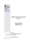
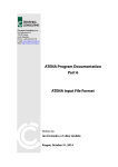
The resulting figure can be copied to the clipboard or printed using the same procedure as
it is described in Section 5.2.
5.7 Diagrams of internal forces
The ATENA program version 1.2.0 and younger contains a unique feature that enables the
calculation of moment, shear and normal forces diagrams for beam-like structures. The
user only has to specify the center line, to which the internal forces are to be calculated.
This moment line can be only defined in the pre-processing window, but it does not have
to specified before the analysis. It can be defined any time during the whole analysis
process just by switching into the pre-processing model using the button
.
The moment line definition starts in the pre-processing window by selecting the item
Moment lines in the data access tree in the left side of the program window. After that the
procedure is an analogy to the definition of reinforcement bars or cuts (see Section 3.7 or
5.6). It is again possible to define the line geometry by mouse or by numerical values. The
graphical input can be activated using the button
.
In this example the numerical input is used, and it is started by the Add button in the
Moment lines table window, which appears at the bottom of the program window, after
the item Moment lines is highlighted in the data access tree.
Step 3: click on Add to
define moment line
segments
Step 5: after the definition
of all segments click Add
to include the created
moment line into the
table.
After all moment lines are
defined use End to return
Step 4: define coordinates and
geometry of each segment.
After each segment click Add
and use End to close the input
window.
Step 1: highlight
the item
Moment lines
Step 2: select the button Add to
define new moment lines
Figure 79: The procedure for the definition of moment lines for the calculation of internal
forces.
48