1
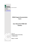
Cervenka Consulting Ltd.
Na Hrebenkach 55
150 00 Prague
Czech Republic
Phone: +420 220 610 018
E-mail: [email protected]
Web: http://www.cervenka.cz
ATENA Program Documentation
Part 4-1
Tutorial for Program ATENA 2D
Written by:
Jan Červenka
Prague, May 16, 2001
Copyright © 2000-2001 by Cervenka Consulting.
Trademarks:
Microsoft and Microsoft Word are registered trademarks of Microsoft Corporation
.
Table of Contents
1.
INTRODUCTION
1
2.
STARTING PROGRAM
1
3.
PRE-PROCESSING
2
3.1
Introduction
2
3.2
Material parameters
5
3.3
Geometrical joints
10
3.4
Geometrical lines
13
3.5
Geometrical macro-elements
15
3.6
Mesh generation
19
3.7
Bar-reinforcement
20
3.8
Supports and actions
23
3.9
Loading history and solution parameters
27
3.10
Monitoring points
30
4.
FE NON-LINEAR ANALYSIS
4.1
Introduction
33
4.2
Starting analysis
34
4.3
Interactive window
35
4.4
Adding new load steps
36
5.
POST-PROCESSING
5.1
Introduction
37
5.2
Post-processing window
37
5.3
Load-displacement diagrams
42
5.4
Text output
43
5.5
Analysis log files
44
5.6
Cuts
45
5.7
Diagrams of internal forces
48
6.
CONCLUSIONS
51
7.
PROGRAM DISTRIBUTORS AND DEVELOPERS
52
8.
LITERATURE
55
33
37
1. Introduction
This tutorial provides a basic introduction to the usage of the program ATENA 2D and it
is specifically targeted to ATENA 2D beginners. This tutorial contains a step by step
explanation how to perform a non-linear analysis on an example problem of a reinforced
beam without smeared reinforcement. The geometrical and material properties correspond
to the experimental setup by Leonhard in 1962. More details about the problem or
experiment can be also obtained from the original report [5] or from the program developer
or distributor.
The step by step demonstration is performed on an example of simply supported beam,
which is loaded by two loads as it is shown in Figure 1. The problem is symmetric around
its vertical axis, therefore, only one symmetric half of the beam will be analyzed.
The steps necessary for the data preparation, non-linear analysis and post-processing are
depicted on subsequent figures, which show the computer screen for each step and user
action. There is always also a short description for each figure. In the post-processing stage
only some basic post-processing methods are described. ATENA offers many options for
viewing results from FE non-linear analysis. These options can be easily accessed from the
post-procesing window by self-explanatory buttons and toolbars. For more details, it is
recommended to consult the ATENA 2D user's manual or the hotline desk at the program
distributor or developer.
Figure 1: Geometry of the structure.
2. Starting Program
Executing the program CCATENAGUIX.EXE from the directory where the program is
installed can start ATENA 2D. The letter X indicates the program version number, or the
program can be more conveniently started from Start | Programs menu on your
computer desktop.
1
3. Pre-processing
3.1 Introduction
This chapter explains the basic steps, which are to be performed in order to define a
complete geometrical and then a finite element model for non-linear FE analysis by
ATENA. The purpose of the geometrical model is to describe the geometry of the
structure, its material properties and boundary conditions. The analytical model for the
finite element analysis will be created during the pre-processing with the help of the fully
automated mesh generator. The geometrical model is created in the following steps. First,
geometrical joints are defined. These joints are later connected into boundary lines. It is
possible to create straight, arc or circular lines. The subsequent step is to define macroelements or regions, by specifying a list of boundary lines, which surround the macroelement.
Before starting the definition of the geometrical model it is a good idea to introduce the
graphical user interface of ATENA 2D pre-processor. The pre-processing window is
shown in the subsequent Figure 2.
Main Menu
Button for view
settings
Combo box for display
of supports and loads
Miscellanou
s Toolbars
Toolbar for graphical
input and editing.
Selection of active
load-case
Main view window containing the
created geometrical and FE model.
Access tree for data
definition
Tables for data input and modification.
Table for the active item in the data access tree is shown.
Figure 2: Graphical user interface of ATENA 2D pre-processor.
2
ATENA 2D contains four main toolbars:
File toolbar:
New
problem
Open
file
Save
file
Text
output
Graphical
output
Solution toolbar:
Mesh
generation
Non-linear
finite element
solution
Preprocessing
Post-processing
Zoom and view toolbar:
Previous zoom
Zoom in
at mouse
location
Zoom out
at mouse
location
Zoom
window
Move
3
Zoom in
around
center
Zoom out
around
center
View
all
Selection toolbar:
Select
joints
Select bar
reinforcement
Select
lines
Select
moment
lines
Exit
selection
mode
Select
by
crossing
Select by
skewed
rectangle
Select
macroelements
Select
cuts
Select
by
clicking
Select
openings
Partial
selection
on/off
Select by
rectangle
Invert selection
all objects of the
selected type
Selection mode
add, remove, invert
Deselect
all items of
selected type
Select all
objects of
selected type
Deselect all
selected
objects
After examination of the user interface layout, it is possible to start with the definition of
the geometrical model of the analyzed structure. It is a good practice to provide a short
description of the problem to be analyzed. In ATENA 2D this can be done be selecting the
General data item in the data access tree. This opens the following table in the table
window.
Figure 3: General data table shows general information about the structure.
4
Figure 4: The editing dialog for general data appears after selecting the Edit button from the
General data table.
3.2 Material parameters
Next step should be the definition of material groups and material properties. Selecting the
item Materials from the data access tree opens the Materials table.
Figure 5: The Materials table, from which new materials can be added or existing
materials can be modified or removed.
Clicking the Add button on the material table window creates a new material. For the
current problem it is necessary to define three material types: one plane stress elastic
material for the steel plates at support and loading points, concrete material for the beam
and reinforcement material.
Figure 6: Selection of plane stress elastic isotropic material for the steel plates.
5
Figure 7: The dialog for the definition of material properties for the steel plates.
Figure 8: Selection of material model for the bar reinforcement.
Figure 9: The dialog for the definition of reinforcement material parameters. The bi-linear
elastic-perfectly plastic stress-strain diagram is selected for this problem.
6
Figure 10: Selection of SBETA material model for the concrete beam. The SBETA model
corresponds to the material formulation, which was implemented in the program SBETA.
SBETA was a previous DOS version of ATENA.
Figure 11: Default values of material parameters are generated based on the cube strength of
concrete. For this case, the cube strength should be 33.5 MPa.
Figure 12: The dialog window for the definition of basic properties for SBETA material. The
parameters were generated based on the concrete cube strength. The tensile strength should be
edited to 1.64 MPa for the Leonhard's beam.
7
Figure 13: The dialog window for the tensile properties for SBETA material.
Figure 14: The dialog window for the compressive properties of SBETA material.
Figure 15: The dialog window for the shear properties of SBETA material.
8
Figure 16: The dialog window for the miscellaneous properties of SBETA material.
Figure 17: The three materials, which were defined previously, can be viewed or modified
from the Material table window.
9
3.3 Geometrical joints
Next step in the input data preparation should be the definition of geometrical joints. The
geometrical joints will be later connected to geometrical lines and macro-elements (i.e.
regions). Selecting the appropriate item (i.e. Joints) in the access data tree can start the
definition of geometrical joints. After that it is possible to continue in two ways: either by
, which will be followed by mouse picking at new joint locations,
selecting the button
or by clicking the Add button in the Joints table window.
Figure 18: The dialog for specifying the coordinates and properties for the newly created joints.
Table 1 contains the coordinates for the geometrical joints, which are necessary to fully
define the geometry of the Leonhard's shear beam.
10
Table 1: Coordinates of the geometrical joints.
Joint Num. Coordinate x [m]
Coordinate y [m]
1
0.0000
0.0000
2
0.0000
0.3200
3
0.2500
-0.0300
4
0.2500
0.0000
5
0.3000
-0.0300
6
0.3500
-0.0300
7
0.3500
0.0000
8
1.0725
0.3200
9
1.0725
0.3500
10
1.1100
0.3500
11
1.1475
0.3500
12
1.1475
0.3200
13
1.2750
0.0000
14
1.2750
0.3200
In case a typing mistake is made during the input of coordinates, it is possible to edit
wrong geometrical joints. There are two possibilities to access joint coordinates and other
properties.
The first possibility is to use the Joints table window. In this case, the geometrical joint to
be edited is selected by double-clicking on it in the table or using the Edit button.
The other possibility is to select the joint in the window containing the view of the
structure. In this method, the Joint item in the data access tree should be highlighted, and
the edit button
must be selected from the toolbar for graphical input and editing. Then
geometrical joint properties can be modified just by clicking at an appropriate joint. The
same philosophy can be used to edit other geometrical entities as lines, macro-elements
and reinforcement bars.
11
Use this button to
scale the view
such that the joints
fill the whole
window
Figure 19: The program window after the definition of all geometrical joints.
Zoom to fit
button
Figure 20: The program window after the selection of the zoom to fit button.
12
3.4 Geometrical lines
After the definition of the geometrical joints, it is possible to proceed with the definition of
geometrical lines, which will connect the previously specified joints.
Figure 21: The definition of geometrical lines begins by selecting the Line item in the data
access tree. The graphical definition of geometrical lines starts by clicking the button
.
If needed spring
support can be
added along
lines.
If needed mesh
refinement around
lines can be selected.
Figure 22: The line prototype dialog box appears after clicking the button
. In this dialog a
mesh refinement method or line springs can be specified. All subsequently created lines will
use this set of prototype properties.
13
Figure 23: In the graphical mode, a geometrical line is defined by first selecting a line
beginning and a line end joint by mouse. The order of end points is not important in ATENA.
Figure 24: Program display after the definition of the first boundary line.
14
Figure 25: The program display after the definition of all geometrical lines.
3.5 Geometrical macro-elements
After the definition of geometrical lines, the next step is to connect these lines to form
regions. In ATENA 2D regions are called macro-elements. The regions can be again
defined in two ways: either from the Macro-element table window by selecting the button
Edit and by providing a list of boundary lines, or graphically using the mouse to select the
boundary lines for macro-elements.
The second and more convenient approach starts by highlighting the item Macro-elements
should be selected. After that
in the data access tree (see Figure 26). Then the button
a dialog window, which is shown in Figure 27, appears for the specification of macroelement properties. These properties will be used in the subsequently created regions. We
will start with the definition of regions for the steel plates that are located at the loading
point and at the vertical supports. Mouse clicking selects lines that form a macro-element.
It is possible to note that the shape of the mouse pointer changes when it is close to a
particular line.
The button
can be used to edit macro-element properties. The button
removing macro-elements, and the buttons
setting new prototype properties respectively.
15
and
is for
for getting information and
Figure 26: Program display at the beginning of the macro-element definition.
quad-, triangular or mixed
mesh can be selected here.
This value specifies the
requested element size for
automatic mesh generation
A material model for the new
macro-elements
Element type for quadrilateral
elements
Figure 27: The dialog window, which appears after the selection of the button
from the
toolbar for graphical input and editing. This dialog is used for the definition of macro-element
prototype, the properties of which will be used for the subsequently created macro-elements. In
this case we will start with the definition of regions (i.e. macro-elements) for the supporting
steel plates.
16
Figure 28: Selection of boundary lines for first macro-element representing the steel plate at the
vertical support.
Figure 29: Program display after the first steel plate is defined and during the process of
creating the second steel plate, which is located at the point of load application.
17
After the definition of macro-elements for the steel plates, it is necessary to change the
macro-element prototype properties, since for the beam the concrete material is more
suitable than the elastic isotropic one. Clicking the button
properties.
changes the prototype
Figure 30: The dialog for changing the macro-element prototype properties for the beam
region, where concrete material model should be used.
Figure 31: The program display after the definition of the last macro-element with the concrete
material.
18
3.6 Mesh generation
After the definition of macro-elements is completed it is possible to start an automatic
. The
mesh generation. The automatic mesh generation is executed using the button
mesh generator in ATENA 2D is fully automatic. Based on element sizes that are defined
for each macro-element a finite element mesh is generated automatically. The created
mesh size can be controlled by local refinements around geometrical lines and joints. It is
useful to note that when the generator recognizes that the macro-element is composed of
four edges with same number of divisions along the opposite edges, it attempts to generate
a mesh using the mapping technique. This feature can be useful in some cases when nice
and uniform meshes are required. This feature of the mesh generator, however, is not
exploited in this example, and we rely on the capabilities of the fully automated meshing.
Figure 32: Generated finite element mesh using the element size of 0.08 m.
19
3.7 Bar-reinforcement
In the next step reinforcing bars will be defined. It should be noted that reinforcement bars
can be defined any time during the input data preparation. It is not necessary to wait till the
macro-elements are defined and mesh is generated. The reinforcement bar definition starts
by highlighting the Bar reinforcement item in the data access tree (see Figure 33). Then
it is again possible to define the bar geometry by mouse or by numerical values. The
graphical input can be activated using the button
.
In this example the numerical input is used, and it is started by the Edit button in the Bar
reinforcement table window.
Use these buttons for graphical input and editing.
This button starts the numerical input
of reinforcing bars.
Figure 33: The program window at the beginning of the reinforcement bar definition.
In this example, there is only one reinforcing bar along the bottom side of the beam. The
bar distance from the beam bottom surface is 0.05 m. In reality, this bar models two bars
with diameter of 26 mm. The steps necessary to create a new reinforcement bar in ATENA
2D are documented in the subsequent figures.
20
Geometric non-linearity
can be selected here.
Figure 34: The dialog for the definition of reinforcement bars contains two property
sheets. The sheet Properties is used for the definition of material model and
reinforcement cross-sectional area.
Click Add button
to define the coordinates
of the bar beginning.
Figure 35: The sheet Topology is used for the definition of bar geometry. A reinforcement
bar is composed of segments, and each segment can be a line, arc or a circle.
21
Select segment type Line, and then define the end point coordinates
Figure 36: This figure shows the definition of the bar end point.
Figure 37: The program display after the definition of the reinforcement bar.
22
3.8 Supports and actions
This section describes the definition of supports and loads for our example problem.
The analyzed beam is supported at the bottom steel plate in the vertical direction. Since we
are analyzing only a symmetric half of the beam, it is necessary to enforce the axis of
symmetry along the line 5. Horizontal displacements along this line should be equal to
zero.
The beam is loaded at the top steel plate. We are interested in determining the maximal
load-carrying capacity of the beam, which means we want to be able to trace the structural
response also in the post-peak regime. The easiest method to accomplish this is by loading
the beam by prescribed displacements at the top steel plate. It is possible to apply the
loading by vertical forces, which will be increased in each load step. In order to be able to
go into post-peak, advanced non-linear solution strategies such as Arc-length method
would be necessary. Such techniques are available in ATENA 2D, but they will not be
used in this example, where Newton-Raphson method and displacement load control is
sufficient.
A loading history in ATENA 2D is defined in analogy to previous version SBETA. This
means that first load cases are defined, and then they are combined together to form a
loading history for an analyzed structure.
For this example, two load cases are defined: one containing the vertical and horizontal
supports, and second with the prescribed deformations at the top steel plate.
Figure 38: The load-case definition starts by highlighting the Load-cases item in the data
access tree and clicking the Add button in the Load cases table.
23
Figure 39: The first load case will contain the horizontal and vertical supports.
Figure 40: The second load case will contain the prescribed deformation at the top steel plate.
Figure 41: The list of created load-cases in the Load cases table.
24
Active load case selection
Figure 42: An appropriate active load case must be selected before the definition of supports.
Supports should be in the load case 1.
(2) Choose joint and
line selection mode
(3) Choose
selection
(1) Highlight
Joint item
(4) Select joint
5 for support
application
(5) Click
Replace button
and set fixed in
Y direction
Figure 43: The definition of the vertical support at the bottom steel plate.
25
(2) Select
line 5 for
support
application
(1) Highlight
Line item in the
data access tree
(3) Click Replace
button and specify
fixed support in x
direction.
Figure 44: The definition of horizontal support along the line 5.
(1) Select load
case 2
(2) Deselect all previously
selected entities!!!!
(4) Select
joint 10 for
the load
application
(3) Highlight
item Joint
(5) Click Replace and
define direction and
displacement value
Figure 45: The definition of the prescribed displacement at the top steel plate in load case 2.
26
3.9 Loading history and solution parameters
This section describes the definition of loading history for the analysis of Leonhardt's shear
beam. The loading history consists of load steps. Each load step is defined as a
combination of load cases, which had been defined previously. Each load step contains
also a definition of solution parameters, which define solution methods that are to be used
during the load steps. ATENA 2D contains a standard set of solution parameters. The
standard solution parameters can be examined in the table of Solution parameters. This
table appears in the table window after highlighting the Solution Parameters item in the
data access tree.
Figure 46: The program display with the table of solution parameters. Standard solution
parameters can be examined by clicking the button Show. New set of solution parameters can
be created using the button Add.
27
Figure 47: The first property sheet for the new set of solution parameters for Leonhardt's beam
analysis.
Figure 48: The second property sheet for the new set of solution parameters parameters for
Leonhardt's beam analysis.
28
Figure 49: The table with the newly created solution parameters.
Figure 50: Load steps are specified using the button Add from the table of Analysis
steps. This table appears in the table window after highlighting the Analysis steps item in
the data access tree.
Figure 51: Each step will be composed of load cases 1 and 2. The multiplier 3 will be used to
multiply the applied actions and the newly created solution parameters will be used during the
load steps.
29
Figure 52: The Analysis steps table after the definition of twenty load steps with the above
parameters. It is possible to add more load steps later during the analysis.
3.10 Monitoring points
During non-linear analysis it is useful to monitor forces, displacements or stresses in the
model. The monitored data can provide important information about the state of the
structure. For instance from monitoring of applied forces it is possible to determine if the
maximal load was reached or not. Monitoring points can be defined by highlighting the
Monitoring points item in the data access tree. Then it is again possible to use graphical
or alpha-numerical specification of the monitoring point location. The graphical input is
activated by the button
, and follows by the selection of the exact location by mouse.
The alpha-numerical input starts by the button Add from the table of Monitoring points.
For this example, the first monitoring point should be added near the joint where the
prescribed displacements are applied. The second component (i.e. y direction) of nodal
applied forces should be monitored at this point. It is not necessary to define a location
exactly at the finite element node. The program automatically selects the closest FE node.
In case monitoring at integration points is required, the closest finite element integration
point is selected.
The second monitoring point should be located at the middle of the beam near its bottom
surface, where the largest vertical displacements can be expected. The second component
(i.e. y-displacement) of nodal displacements should be monitored at this location.
These two monitoring points will allow us to monitor the load-displacement curve during
the non-linear finite element analysis. It makes it possible to see the changes of action
forces and displacement at each load step and even in each iteration. The program display
after the definition of the monitoring points is shown in Figure 55.
30
Figure 53: The definition of the first monitoring point.
Figure 54: The dialog window for the definition of the second monitoring point.
31
Figure 55: The program display after the definition of monitoring points.
This buttons returns to
the view of the whole
structure.
This button activates
the zoom rectangle
Figure 56: The way, in which the program selects the closest node for monitoring becomes
more apparent after zooming at the middle section of the beam. The button
view to the state when the whole structure is displayed.
32
returns the
4. FE non-linear analysis
4.1 Introduction
This section describes the process of running a non-linear finite element analysis of the
Leonhardt beam using the data that have been prepared in the previous sections of this
tutorial.
Before finite element analysis it may be useful and interesting to view the finite element
mesh numbering. The finite element model numbers can be displayed through the view
setting button
, which appears at the left top corner of the view window. This actions
opens a dialog window (see Figure 57) that can be use to select the data to be displayed in
the view window. Among others it is possible to turn on/off numbering of finite elements,
nodes or geometrical entities, turn on/off the display of reinforcement bars or monitoring
points.
Figure 57: The dialog box for activating the display of finite element node and element
numbers.
33
Figure 58: The finite element mesh along with node and element numbers. The size of
characters can be modified from the menu item Options | Settings.
4.2 Starting analysis
The finite element analysis is started using the button
. After clicking this button an
initialization dialog window appears on the computer screen. This dialog window is shown
in Figure 59, and it can be used to select the load step when the analysis will be terminated
and data to be displayed in the L-D diagram. In addition, the load steps can be specified, in
which results should be saved, in this dialog. Please note that it is not possible to perform a
post-processing for the steps, in which the results were not saved.
Figure 59: The dialog window before the finite element analysis.
34
4.3 Interactive window
After the button Analyse in the dialog, which is shown in Figure 59 is selected, the actual
finite element analysis is started. The analysis progress can be monitored using the
interactive window that is shown in Figure 60.
Figure 60: The interactive window for monitoring the progress of non-linear analysis.
Figure 61: The interactive window after selecting a different format of the L-D diagram. The
L-D diagram in this figure shows the iterative changes of the monitored quantities.
35
4.4 Adding new load steps
After the first 20 load steps are completed it is possible to specify additional 20 load steps.
In order to define additional load steps it is necessary first to switch to the pre-processing
mode using the button
. After the specified steps are completed the program
automatically enters the post-processing mode. It is necessary to switch into the input
mode before new steps can be defined.
The new load steps are defined in analogy to the process described in Section 3.9 by
adding new analysis steps in the Analysis steps table.
Figure 62: The dialog box for the new analysis steps. Same properties are used as in Section
3.9.
Figure 63: The table with the analysis steps after the definition of additional 20 steps.
After the definition of new load steps, the analysis can be restarted again by clicking the
button
.
36
5. Post-processing
5.1 Introduction
After the finite element analysis is completed or terminated, the program automatically
enters into the post-processing mode. The post-processing can be entered also by clicking
the button
. This action is meaningful only after the analysis has been performed,
otherwise there would be no results to visualize.
5.2 Post-processing window
The layout of the post-processing window is shown in Figure 64. The first step in postprocessing is to select the analysis step (i.e. load step), from which the results are
requested. The program loads the data for the requested load step into the computer
memory and fills in appropriately the lists of available output quantities. The type of
analysis and used material models determines the available output data.
Select load step, which results are to be visualized.
Select scalar data for rendering, contour areas or isolines
Figure
64: The post-processing window containing contour areas, cracks and
reinforcement stresses for the last load step 40.
37
Figure 65: The display of reinforcement bar stresses and cracks is activated by clicking an
appropriate label in the toolbar along the left side of the program window.
Select display of principal strain vectors and
values.
Figure 66: The post-processing window with rendering and principal vectors of maximal
principal strains for the last load step 40.
38
The zoom button can be used to display
a detailed picture of a critical part of
the structure
Figure 67: The post-processing window with zoom, rendering and principal vectors of
maximal principal strains for the last load step 40. If a user selects the item show with label, the
numerical values of the principal strains will be displayed as well.
These buttons can be used to turn on the
display of loads and boundary
conditions (available only for
undeformed shapes).
If an output in element nodes is selected, the
results are not interpolated between elements, and
it is possible to observe the inter-element strain
jumps
Figure 68: The post-processing window with rendering of element data for the last load step
40. This figure shows also the undeformed configuration with support and loading conditions.
The undeformed shape is selected by the following button
39
.
It is possible to open several post-processing windows at the same time. Each window can
be used to show results from different load steps. A new post-processing window can be
opened using the menu item Windows | New | View.
The active post-processing window can be printed from the menu item File | Graphic
printout… or copied to the clipboard from Edit | Copy picture. The copied picture can be
for instance pasted to a Microsoft Word document. The picture remains in vector format so
it can be easily scaled or resized while preserving its resolution for printing.
It is possible to modify some parameters controlling the display on the screen or on paper
with the help of the dialog Options | Settings. This dialog and some of its features are
described in the subsequent figures.
Figure 69: The dialog sheet General contains various checkboxes affecting the clipboard and
printing functions. The block Run enables the user to edit the program input file before the
numerical calculation are started. This option should be used only by the experience users, since
wrong editing can cause a program crash and can result in a loss of data.
Figure 70: The dialog sheet Font controls the size of labels on the computer monitor and in the
printer.
40
Figure 71: The dialog sheet Crack display enables the definition of line thickness that will be
used for drawing cracks with the largest opening.
41
5.3 Load-displacement diagrams
The important information about the structural behavior can be obtained from the data
collected during the analysis at the monitoring points. In our case the force at the point of
load application and the maximal vertical displacement were monitored. The loaddisplacement diagram can be displayed as another post-processing window from the menu
item Windows | New | Graph. An empty window appears on the computer screen. Next
step is to select which monitored quantities are to be plotted on X and Y-axes.
Figure 72: The load-displacement diagram.
The buttons in the top right hand corner of the graph window can be used to modify the
diagram appearance. The button
load steps, while the button
the iterative process. The buttons
display.
selects the display of monitoring data at the end of
displays the quantities as they had been changing during
can be used to change the quadrant for the graph
The selected diagram can be printed or copied to the clipboard in the same manner as it
was described in Section 5.2. The numerical values of the monitored quantities can be
obtained from the text output that is described in Section 5.4.
42
5.4 Text output
This section describes another form of output from the program ATENA 2D. The text
output can be used to obtain numerical data at finite element nodes, elements, integration
points or monitoring points. The text output is selected from the menu item File |
Text printout…. This selection opens the window that is shown in Figure 73. The
window is composed of two main sub-windows. The left-hand window contains a tree
structure of the available data types. The requested data should be checked in this tree, and
then by clicking the button Generate, an alphanumerical output will be created in the
right-hand window. The contents of this window can be printed, saved to a file or copied to
another program using the system clipboard.
Figure 73: The program window for the definition of alfa-numerical output.
43
5.5 Analysis log files
The program ATENA 2D consists of several modules. The two main modules are the
graphical user interface (GUI) and the analysis module. These two modules communicate
with each other through the Microsoft component object model (COM) interfaces and also
through four file streams. The contents of these streams for each analysis step can be
examined using the menu item Calculations | Step information. This action
opens the following window on your computer screen:
Figure 74: The step information window contains the input and output files from the finite
element analysis.
It is possible to view the contents of these data streams for each analysis step, which can be
selected from the pull-down list at the top of the window. The content of each data stream
can be examined by selecting an appropriate bookmark at the top part of the window.
The input stream contains the commands that were passed from the GUI to the analysis
module. In the first step, it contains the definition of the numerical model. In the
subsequent load steps it contains the definition of supports, loads and solution parameters.
The format of this file is described in the ATENA Input File Format manual [4]. The
advanced users can modify the contents of this file before executing the analysis if proper
settings are defined in Options | Settings. Only users experienced with the program
ATENA and the format of this file should modify the input file, otherwise they can
damage their data, which may then become unusable.
The output stream contains the output from the analysis module. Normally this stream is
empty since it is used later when text output is requested.
44
The message stream contains the information about the analysis progress as they appeared
also in the interactive window during the non-linear analysis.
The error stream contains error and warning messages from the analysis modules. This
stream should be examined for errors that might have occurred during the numerical
calculations.
5.6 Cuts
Starting from version 1.2.0 or younger, the program ATENA 2D enables the definition of
cuts, along which scalar quantities can be evaluated and displayed. The cut can be a single
straight line, an arc, or a polygon consisting of straight lines or arcs. The cuts must be
defined in the pre-processing window, but does not have to be defined before the
numerical analysis. It is possible to define them even after some results and load steps are
calculated, just by switching between the pre- and post-processing windows.
The cut definition starts in the pre-processing window by selecting the item Cuts in the
data access tree in the left side of the program window. After that the procedure is an
analogy to the definition of reinforcement bars (see Section 3.7). It is again possible to
define the cut geometry by mouse or by numerical values. The graphical input can be
activated using the button
.
In this example the numerical input is used, and it is started by the Add button in the Cut
table window, which appears at the bottom of the program window, after the item Cuts is
highlighted in the data access tree.
Step 3: select Add to start the
definition of cut segments
Step 5: use Add to add
the cut to the table and
End to finish the cut
definition.
Step 4: input cut
coordinates. Finish each
segment definition with
Add. Use End after the
last segment.
Then use Add to add cut
to the table.
Step 1:
select the
item Cuts
Step 2: select the button Add to add a
cut to the table of cuts.
Figure 75: The beginning of the numerical definition of cuts.
45
Use the procedure above to define two cuts with the following end point coordinates:
Table 2: The coordinates of points for the cut definition.
Cut 1
Cut 2
Beginning
End
Beginning
End
x [m]
0.705
0.705
1.275
1.275
y [m]
0.000
0.320
0.000
0.320
Then the program window shows the structure with two vertical cuts denoted by yellow
color.
Figure 76: The program window shows two cuts after the cut definition.
When the cuts are defined, it is possible to switch into the post-processing mode (the
button
). In this window it is possible to select which quantities are displayed along the
cut lines. Same data as in the scalar plot are always displayed along the cuts, therefore the
cut display is controlled from the Scalar sheet in the post-processing toolbar that is
normally located along the left edge of the program window. The combo-box item Show
cuts with labels must be selected in order to see the display of cut data (see Figure 77).
46
The item Show cuts with labels displays the
cut lines and the evolution of the selected
quantity.
These two boxes controls, which data are
evaluated along the cuts.
Figure 77: The post-processing window with the display of cut lines.
If necessary the display of certain cuts can be deactivated using the main menu item
Options | Activity. In this dialog it is possible to define which cuts, reinforcements or
moment lines are to be displayed on your computer screen.
Figure 78: The visibility of cuts, moment lines or reinforcement bars can be specified from the
main menu item Options | Activity.
47
The resulting figure can be copied to the clipboard or printed using the same procedure as
it is described in Section 5.2.
5.7 Diagrams of internal forces
The ATENA program version 1.2.0 and younger contains a unique feature that enables the
calculation of moment, shear and normal forces diagrams for beam-like structures. The
user only has to specify the center line, to which the internal forces are to be calculated.
This moment line can be only defined in the pre-processing window, but it does not have
to specified before the analysis. It can be defined any time during the whole analysis
process just by switching into the pre-processing model using the button
.
The moment line definition starts in the pre-processing window by selecting the item
Moment lines in the data access tree in the left side of the program window. After that the
procedure is an analogy to the definition of reinforcement bars or cuts (see Section 3.7 or
5.6). It is again possible to define the line geometry by mouse or by numerical values. The
graphical input can be activated using the button
.
In this example the numerical input is used, and it is started by the Add button in the
Moment lines table window, which appears at the bottom of the program window, after
the item Moment lines is highlighted in the data access tree.
Step 3: click on Add to
define moment line
segments
Step 5: after the definition
of all segments click Add
to include the created
moment line into the
table.
After all moment lines are
defined use End to return
Step 4: define coordinates and
geometry of each segment.
After each segment click Add
and use End to close the input
window.
Step 1: highlight
the item
Moment lines
Step 2: select the button Add to
define new moment lines
Figure 79: The procedure for the definition of moment lines for the calculation of internal
forces.
48
Use the above steps to define a centerline that is composed of only one linear segment
starting at the coordinates (0;0.16) and extending up to the point (1.275;0.16).
Figure 80: The pre-processing window after the specification of one moment line: coordinates
(0;0.16) -> (1.275;0.16).
The diagram of the internal forces distribution can be obtained only when the program is in
a post-processing mode, therefore, the next step is to select the button
visualization mode.
to enter the
There is a special sheet: Moment lines, in the post-processing toolbar along the left side of
the program window. If it is selected and if the top box shows the note: show and label the
diagrams of moment, normal and shear forces are displayed on the screen as it is shown in
Figure 81. Please note that if a display of iso-lines or vector plot has been previously
selected, it remains on the screen, and the internal forces diagram is drawn over the
original picture. In many cases this is what the user wants, otherwise the iso-line or vector
display must be deactivated using the appropriate sheets in the left side toolbar.
49
Select the item show and label to see the MNQ diagram.
This box controls how the forces are calculated. It can be
either from element stresses or from the stresses that are
interpolated to the finite element nodes.
These check-boxes select which diagram appears on the
monitor: M – moment, N – normal force, Q – shear force.
Figure 81: The diagram of internal forces in the post-processing window.
The program ATENA 2D offers two methods for the calculation of the internal forces. A
suitable method can be selected from the second box in the Moment lines sheet in the
post-procesing toolbar, which is normally located along the left side of the program
window. The first method calculates the internal forces from stresses that are interpolated
and averaged at nodes. The second approach calculates the forces directly from stresses at
element nodes. In this method there is no averaging of stresses between elements. The first
method tends to smooth the stress field, and therefore, it can hide some spikes from being
considered in the internal forces calculation.
50
6. Conclusions
This tutorial provided a step by step introduction to the usage of ATENA 2D on an
example of a reinforced concrete beam without shear reinforcement. Although this
example is relatively simple from geometrical and topological point of view, it is not a
simple problem from the numerical point of view. Due to the missing shear reinforcement
the beam fails by a diagonal shear crack, which is very difficult to capture using smeared
crack approach. This example demonstrates the powerful simulation capabilities of
ATENA for modeling the brittle failure of concrete structures. Even with very coarse
mesh, which was used in this demonstration example, the diagonal shear crack was
successfully captured. Further improvement of the results can be achieved by decreasing
the finite element size to at least 6-8 elements over the beam height. It is also possible to
select different quadrilateral elements: CCQ10 or CCQ10SBeta, which should exhibit even
better behavior in shear dominated problems.
The objective of this tutorial is to provide the user with basic understanding of the program
behavior and usage. For more information the user should consult the user’s manual [2] or
contact the program distributor or developer. Our team is ready to answer your questions
and help you to solve your problems.
The theoretical derivations and formulations that are used in the program are described in
the theory manual [1].
The experienced users can also find useful information in the manual for the analysis
module only [4].
51
7. Program distributors and developers
Program developer: CERVENKA CONSULTING
Predvoje 22, Prague 6, 162 00, CZECH REPUBLIC
phone/fax: +420 220 610 018
e-mail: [email protected], WWW: www.cervenka.cz
Program distributors:
JAPAN:
Research Center for Computational Mechanics, Inc.
(RCCM)
Mr. Shinjiro Yoshikawa
general director
Togoshi N1-Bldg.
1-7-1 Hiratsuka Shinagawa-ku
Tokyo 142-0041 JAPAN
phone: +813 3785 3033
fax: +813 37 85 60 66
e-mail: [email protected]
WWW: www.rccm.co.jp
GERMANY:
WOELFEL Beratende Ingenieure GmbH + Co.
Bereich Technische Programme
Max-Planck Strasse 15,
D-97204 Hoechberg GERMANY
phone: +49 931 49708-360
fax: +49 931 49708-650
e-mail: [email protected]
WWW: www.woelfel.de
GREAT BRITAIN: Integrated Structural Software ISS
Prioryfield House, 20 Canon Street
TA1 1SW, Taunton, Somerset
52
United Kingdom
Fax: +44-1823-271719
Tel: +44-1823-271717
E-mail: [email protected]
WWW: www.issrobot.co.uk
SOUTH KOREA: YEON Engineering
65, 2nd Floor, ChoungHyo-dong, Kyongju, Kyo
Kyongbuk, South Korea, Zip. 780-250
Fax: +82-54-775-1654
Tel: +82-54-775-1652-3
E-mail: [email protected]
WWW: www.yeons.co.kr
CHINA:
Prof. Xuehue An
Beijing AHSM Science & Technology Development Co.,Ltd.
105, Building No.12,
DongShengYuanGongYu,
HaiDianQu, Beijing, 100083, China
e-mail: [email protected]
AUSTRALIA: Greg Palmer BE PhD
Palmer Technologies Pty Ltd
PO Box 1513
Coorparoo DC Q 4151
www.palmertech.com.au
e-mail: [email protected]
phone: +61 7 38474048
fax: +61 7 3394 4936
Albert Allan,
Australian Engineering
Suite 7, 4 Botany street,
Randwick 2031 NSW AUSTRALIA
e-mail: [email protected]
53
FINLAND:
Juha Airola
A&S Virtual Systems Oy
Hameentie 153 C
FIN-00560 Helsinky, Finland
Tel: +358 9 2518 0230
Fax: +358 9 2518 0239
e-mail: [email protected]
WWW: www.virtualsystems.fi
54
8. Literature
[1] ATENA Program Documentation, Part 1, ATENA Theory Manual, CERVENKA
CONSULTING, 2000
[2] ATENA Program Documentation, Part 2-1, ATENA 2D User’s Manual, CERVENKA
CONSULTING, 2000
[3] ATENA Program Documentation, Part 3, ATENA Examples of Application,
CERVENKA CONSULTING, 2000
[4] ATENA Program Documentation, Part 6, ATENA Input File Format, CERVENKA
CONSULTING, 2000
[5] Leonhardt and Walther, Schubversuche an einfeldringen Stahlbetonbalken mit und
Ohne Schubbewehrung, Deutscher Ausschuss fuer Stahlbeton, Heft 51, Berlin 1962,
Ernst&Sohn.
55