1
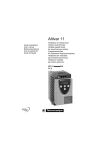
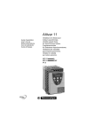
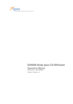
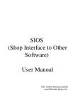
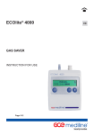
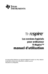
Cardiac Output
User Manual
Part Number: xxxxxxx ENG
Version / Revision: A
Cardiac Output
User Manual
Disclaimer
Information in this manual is subject to change without notice and does not represent
a commitment on the part of nSpire Health. The software described in this document
is furnished under a license agreement. The software may be used or copied only in
accordance with the terms of the agreement. It is against the law to copy the
software on any medium except as specifically allowed in the license or
nondisclosure agreement. No part of this manual may be reproduced or transmitted
in any form or by any means, electronic or mechanical, including photocopying and
recording, for any purpose without the express written permission of nSpire Health
The software is provided "as is" without warranty of any kind, either expressed or
implied including but not limited to the implied warranties of merchantability or fitness
for a particular purpose. Some states do not allow the exclusion of implied
warranties, so the above exclusion may not apply to you. This warranty gives you
specific legal rights and you may also have other rights which vary from state to
state.
nSpire Health does not warrant that the functions contained in the system will meet
your requirements or that the operation of the system will be uninterrupted or error
free.
In no event will nSpire Health be liable to you for any damages, including any lost
profits, lost savings or other incidental or consequential damages arising out of the
use or inability to use such system even if nSpire Health or an authorised nSpire
Health dealer or distributor has been advised of the possibility of such damages, or
for any claim by any other party.
In the event you should have any claim, whether based on the license agreement,
express or implied warranty or otherwise, you agree to accept refund of your money
in full satisfaction of your claim.
Some states do not allow the limitation or exclusion or liability for incidental or
consequential damages so the above limitation or exclusion may not apply to you.
www.nspirehealth.com
Manufactured for
nSpire Health Inc
1830 lefthand Circle,
Longmont, Colorado, 80501,
USA
Tel: 1.800.574.7374
Email: [email protected]
Authorized Representative
nSpire Health Ltd
Unit 10, Hartforde Court
John Tate Road
Hertford, SG13 7NW
U.K.
Tel: (+44) (0) 1992.526.300
Email: [email protected]
nSpire Health GmbH,
Schlimpfhofer Strasse 14
D-97723 Oberthulba
Germany
Tel:
(+49) 097.36.8181.17
(+49) 097.36.8181.27
Email: [email protected]
Cardiac Output
User Manual
Preface
Thank you for purchasing the Cardiac Output option.
The product complies to the newest state of technical development. In order to improve the lifetime of
this product, only materials of extremely high quality are used. All materials are environmentally safe
and can be recycled.
The manual provides instructions for set up and use the cardiac output option together with the ZAN
600 device.
The instructions in this manual assume the user is familiar with the intended use and application of
pulmonary-laboratory systems.
To avoid damage to the devices or incorrect measurement, it is strongly recommended to follow the
introductions in the manual and the technical description.
Your nSpire Health-Team
Schlimpfhofer Str.14
97723 Oberthulba/Germany
Tel. +49 9736 8181-0
Fax +49 9736 8181-20
[email protected]
WWW.NSPIREHEALTH.COM
nSpire Health GmbH
Cardiac Output
User Manual
Table of Contents
1
HISTORY ...................................................................................................................................................... 2
2
THEORETICAL BACKGROUND............................................................................................................. 2
3
OVERVIEW OVER THE PROCEDURE .................................................................................................. 5
3.1
4
MEASURED AND COMPUTED PARAMETERS .................................................................................... 5
HARDWARE SET UP.................................................................................................................................. 7
4.1
REQUIRED COMPONENTS ............................................................................................................ 7
4.2
ASSEMBLY STEP 1....................................................................................................................... 8
4.3
ASSEMBLY STEP 2....................................................................................................................... 9
4.4
ASSEMBLY STEP 3..................................................................................................................... 10
4.5
ASSEMBLY STEP 4..................................................................................................................... 11
4.6
ASSEMBLY STEP 5..................................................................................................................... 12
4.7
ASSEMBLY STEP 6..................................................................................................................... 13
5
SOFTWARE OVERVIEW ........................................................................................................................ 14
6
MEASUREMENT GUIDELINES............................................................................................................. 15
7
PERFORMING A MEASUREMENT ...................................................................................................... 15
7.1
SYMBOL DEFINITION .................................................................................................................. 16
8
EVALUATION............................................................................................................................................ 17
9
END OF MEASUREMENT....................................................................................................................... 17
10
REVIEWING CARDIAC OUTPUT MANOEUVRES........................................................................ 18
ZAN 600 Cardiac Output
1 - 19
Part No. *****.A
Cardiac Output
User Manual
Cardiac Output Using the Fick Principle
1 History
The Fick principle was first described in 1870 by Adolph E. Fick. a German
physiologist (1829-1901), after introducing his law of diffusion in 1855, which allows
to calculate the diffusion of a gas across a membrane and which has been named
after him.
Depending on how the gas measurement is done, two different ways to use the
Fick principle are in use.
The direct Fick method uses blood gas analysis and is an invasive Method. The so
called 'indirect Fick' uses measurement of inhaled and exhaled gas in the breath to
measure the cardiac output and is a non-invasive method.
nSpire Health provides a procedure based on the 'indirect Fick principle'.
2 Theoretical Background
In a simplified model of the human blood circuit, all blood from the body is pumped by the right heart
through the lung and from here to the left heart from where it is pumped through the body again. All
blood, which runs through the lung must be pumped through the left heart to the body again or the
lung is flooded with blood and the person will die. Therefore in healthy humans we can approximately
say that all the blood, which passes the lung is the amount of blood pumped by the heart, the cardiac
output.
Simplified model of the human blood circuit
The indirect Fick method is a way to approximate the amount of blood that perfuses the lung by
measuring the CO2 exhalation.
For CO2 we can write:
ZAN 600 Cardiac Output
2 - 19
Part No. *****.A
Cardiac Output
User Manual
The mass of CO2 in the pulmonary artery Mp is equal to the mass of CO2 exhaled Mex and the mass of
CO2 returning to the left heart Mh.
Masses of a gas can be expressed as concentration multiplied by volume
Using this:
In a closed circuit we can say:
A volume divided by a time is a stream. Dividing both sides of the equation by the time
Abbreviations:
CardOut
=
VCO2
=
CardOut
VCO2
Cp
Ch
= Cardiac output
= CO2 stream measured during tidal breathing
= CO2 concentration in the blood of the pulmonary artery
= CO2 concentration in the blood of the pulmonary vein
Now there is a formula to calculate the cardiac output from the CO2 exhalation, the CO2 concentration
in the blood which arrives in the lung and the CO2 concentration in the blood which leaves the lung.
The CO2 concentration in exhalation stream can be measured directly. What is needed, is to find out
about the CO2 concentrations in the lung vessels before and after it has passed the alveoli.
ZAN 600 Cardiac Output
3 - 19
Part No. *****.A
Cardiac Output
User Manual
CO2 diffusion from the vessel (V) to the alveolus (A)
Carefull examinations proved that the CO2 concentration in the blood which leaves the lung can be
calculated with appropriate accuracy from the the CO2 concentration the at the end of exhalation (end
tidal CO2 concentration).
Indirect Fick Method (non invasive) using a Rebreathing Bag (R) (CO2)
The CO2 concentration of the blood which arrives the lung can be calculated from the the CO2
concentration the at the end of the equilibration while rebreathing into a Douglas bag.
There are two different methods to determine the equilibration point. The extrapolation method by
Defares and the plateau by Collier .The Collier method turned out toprovide the best results for adult
individuals.
Plateau method (Collier) to determine the cardiac output
The method is a good way to approximate the cardiac output especially under load and without
invasive techniques. It is easy to perform the test for both, the test person and the researcher.
The disadvantage is, that the test is not very exact compared to direct methods or Doppler ultra sound
measurement, which both have some problems to provide results under load. The pulmonary shunt
volume is not included in the model which leads to the effect, that the results are more accurate under
load then in rest condition.
ZAN 600 Cardiac Output
4 - 19
Part No. *****.A
Cardiac Output
User Manual
3 Overview over the Procedure
Performing the procedure is easy. All the test person has to do is perform tidal breathing.
The procedures starts with the invocation of the CardOut subroutine or emptying of the bag and then
starting the CardOut programme.
The system is measuring the tidal breath volume and computes the mean values of VT, VCO2 and
PETCO2.
After the test has been started, the system fills the breathing bag with a volume 1.5 times more than
an average tidal breath, with the test gas. The test gas is composed of 10% CO2 and 90% O2
The automatic valve switches to rebreathing position and the measurement is displayed in the
measurement window.
After 12 seconds the system assumes the equilibration to be completed, switches the valve back to
normal breathing position and computes the result line, displayed in the window.
The result line can be adjusted manually to the perfect position. If equilibration takes longer or shorter
than 12 seconds, the time the systems samples data can be modified changing a parameter in the
config.ini file.
After the measurement the system waits 60 seconds to start normal data sampling again, to avoid
artificially high O2 values getting mixed with regular CPET measurement values.
Although the test gas is not harmful to the test person, breathing 10% CO2 is not very comfortable.
Some people feel a increasing hunger for breath and force breathing. With regards to the test, this is a
beneficial effect and leads to quicker equilibration. In any case the test person must be instructed
carefully, so he knows about the effects of the test gas and does not get scared during the procedure.
3.1 Measured and computed parameters
Name
Unit
Meaning
Origin
Vt
[l/min]
Volume flow
measured
VCO2
[l/min]
CO2 volume flow
(is the mean of the last n breaths before start
of equilibration manoeuvre. n is configurable)
measured
PmvCO2
[mm Hg]
mixed venous CO2 partial pressure
(alveolar partial CO2 pressure measured at
rebreathing equilibrium)
measured
PetCO2
[mm Hg]
End tidal CO2 partial pressure
(mean of the last n breaths before start of
equilibration manoeuvre. n is configurable)
measured
SmvO2
[%]
Oxygen saturation: mixed venous
computed
SaO2
[%]
Oxygen saturation: arterial
computed
CmvCO2
[ml/l]
CO2 concentration: mixed venous
computed
CaCO2
[ml/l]
CO2 concentration: arterial
comuted
CardOut
[l/min]
Cardiac output
computed
ZAN 600 Cardiac Output
5 - 19
Part No. *****.A
Cardiac Output
User Manual
Formulas:
cmvco2 = Cco2FromPco2(pmvco2, SmvO2)
caco2
= Cco2FromPco2(petco2, SaO2 )
To convert alveolar partial CO2 pressure to mixed venous/arterial partial CO2 pressure the following
formula is used:
Pa = 5.5 + 0.9 * PA – 0.0021 * Vt
with:
Pa = arterial partial pressure
PA = alveolar partial pressure
Vt = tidal volume
(Jones: Clinical Exercise Testing)
Cco2FromPco2 (X,Y) is a function to extract cmvco2 and caco2 concentrations values from partial
pressures using the curves below
Standard CO2 dissociation curve to convert PCO2 into CCO2.
(Comroe 1959: The Lung. Clinical Physiology and Pulmonary Function Tests.)
ZAN 600 Cardiac Output
6 - 19
Part No. *****.A
Cardiac Output
User Manual
4 Hardware Set Up
4.1 Required Components
The components above are needed to perform the cardiac output measurement according to the
indirect Fick principle:
A.
ZAN600 measurement instrument
B.
ZAN610 controller
C.
Measuring head consisting of:
1.
2.
3.
4.
5.
6.
Ergo Flow Sensor
Pneumo Valve
Breath Filter Adapter
Breath Filter
Breathing Bag Adapter
Breathing Bag
Two set's of tubing are needed:
1. One set with three tubes (colours blue, yellow, white/black) to connect the
ZAN600 with flow sensor and gas suction outlet.
2. And the other set (colours blue, black and yellow) to connect the ZAN610 with the
pneumo valve.
ZAN 600 Cardiac Output
7 - 19
Part No. *****.A
Cardiac Output
User Manual
4.2 Assembly Step 1
Plug together all parts of the measuring head like shown below
Patient side
Make sure the outlet on
the Ergo Flow sensor is
locked with a stopper.
Measuring head assembled
Check, if all parts fit tightly together.
ZAN 600 Cardiac Output
8 - 19
Part No. *****.A
Cardiac Output
User Manual
4.3 Assembly Step 2
Connect the tube with the yellow mark to the "Bag" outlet of the ZAN610 on one side and the
connector of the pneumo valve on the other side as shown in the pictures. The connectors are marked
with arrows.
Gas tube connection at the ZAN610
Connect the gas tube to the bottom part of the pneumo valve
ZAN 600 Cardiac Output
9 - 19
Part No. *****.A
Cardiac Output
User Manual
4.4 Assembly Step 3
Connect the tubes with the black and blue marks to the outlets of the ZAN610. The black tube belongs
to the connector marked as "Valve L" and the blue one belongs to the connector marked as "Valve R"
Tubing at the ZAN610
Next connect the black tube to the left connector of the pneumo valve and the blue one to the right
connector of the valve. Left and right is determined from the patient's point of view.
Black tube in the left and blue tube in the right connector
ZAN 600 Cardiac Output
10 - 19
Part No. *****.A
Cardiac Output
User Manual
4.5 Assembly Step 4
Connect the tube with the black connector to the outlet of the ZAN600 marked with the word "Analyse.
Connection at the ZAN600 side
Connection at the pneumo valve side
Connect the tube from the "Analyse" port to the connector on the top of the pneumo valve (see
above).
ZAN 600 Cardiac Output
11 - 19
Part No. *****.A
Cardiac Output
User Manual
4.6 Assembly Step 5
Connect the tubes with the yellow and blue marks to the outlets of the ZAN600.
Connect the tube with the blue mark proximal and the yellow distal on the flow sensor
ZAN 600 Cardiac Output
12 - 19
Part No. *****.A
Cardiac Output
User Manual
4.7 Assembly Step 6
Connect the tube from the pressure reducer of the gas cylinder to the connector at the back of the
ZAN610.
Gas cylinder
Proper connection of the tube from gas cylinder
Check all connection for tightness.
Connect the USB connectors of the ZAN600 and the ZAN610 devices to the computer.
The set up is now ready to work.
ZAN 600 Cardiac Output
13 - 19
Part No. *****.A
Cardiac Output
User Manual
5 Software Overview
The procedure is part of the cardiopulmonary exercise test software. After starting the CPET option
from the main program, two additional buttons in the top menu are displayed, to control the cardiac
output measurement procedure.
CPET Main Window
The
button (or alternatively press 'P' ) to empty the breathing bag and toggle the pump to test if
all equipment is up and running.
Pressing the
button or the [F5] key opens the measurement window below.
Cardiac output measurement window
Basically all menus have a
higher level.
button ([ESC]) to cancel the current procedure and return to next
It is possible to perform the cardiac output measurement during a running CPET procedure, when the
measurement head is connected to a headset.
ZAN 600 Cardiac Output
14 - 19
Part No. *****.A
Cardiac Output
User Manual
6 Measurement Guidelines
•
Valve of the gas cylinder is open (close again after measurement)
•
Correct gas mixture (10% CO2 and 90% O2, medical gas)
•
Breathing bag must be completely empty before start
•
Use breathing mask or nose clip
•
Take care to protect the test person against tumbling or collapse
Important: We recommend that a doctor or other suitably qualified and experienced physiologist
be present during every stress test. A defibrillator should be available.
The stress test should be terminated if the heart rate, blood pressure or other vital
parameters reach critical values, or if abnormalities become apparent in the ECG
signals.
7 Performing a Measurement
The Patient puts on the nose clip and starts with normal tidal breathing through the mouth piece. If the
patient is under CPET examination, he/she already has the mask on with the measurement head
mounted on the outlet.
Open the cardiac output measurement window by pressing the
[F5] button.
Let the patient perform tidal breathing for at least 5 breaths.
Press the
[P] button to empty the breathing bag. This button has identical functionality as the
button in the CPET menu. (see above).
After the bag is emptied, press the
[Enter] button to start the procedure.
Window before starting the procedure
The system starts filling the bag with test gas with 1.5 times the volume of a single tidal breath.
ZAN 600 Cardiac Output
15 - 19
Part No. *****.A
Cardiac Output
User Manual
When the bag is filled, the window aspect changes and the pneumo valve switches to rebreathing
position
Start of measurement
In the window, the rebreathing curve is displayed. The patient continues breathing.
After a predefined time (default 12 sec.), the display switches to the image below and displays the
results. The pneumo valve switches back to normal position automatically.
Result
End of measurement
7.1 Symbol Definition
Press this button or [Enter] to save the results and end the
procedure
Press this button or the up arrow key to move the result line upwards
one step
Press this button or the down arrow key to move the result line
downwards one step
ZAN 600 Cardiac Output
16 - 19
Part No. *****.A
Cardiac Output
User Manual
Press this button or [ESC] to cancel the procedure without saving
8 Evaluation
Before saving the results with
adjust the result line so that it meets the last measured lower half
wave. This represents the last measured expiration.
Last measured expiration
The result line can be moved stepwise using the
Save the results pressing
[up arrow] and
[down arrow].
or the [Enter] key.
9 End Of Measurement
After the measurement, close the gas cylinder.
After the measurement for a limited time no breath by breath data are recorded. This time is called the
PostTime.
During the equilibration manoeuvre, oxygen is washed into the lungs. Therefore after the manoeuvre,
oxygen is elevated and must be washed out. During washout time, breath-by-breath data are not
recorded. This time interval can be configured as PostTime. This time is 60 sec by default and can be
modified in the config file.
ZAN 600 Cardiac Output
17 - 19
Part No. *****.A
Cardiac Output
User Manual
10 Reviewing Cardiac Output manoeuvres
All manoeuvres can be reviewed offline with a Cardiac-Output-Viewing tool. To review a specific
manoeuvre, open the folder C:\ZAN\GPI200\COP with the Windows Explorer and double-click on the
manoeuvre data file, for example:
ZBodyATSTEST_160309_184250.cop
This will open the correspondent window:
Use the
[up arrow] or
Clicking on toolbar button
calculation.
[down arrow] buttons to move the result line to find a better match.
or the [F3] key displays the primary and secondary data from the
Changes made during this operations will not be saved to disc.
ZAN 600 Cardiac Output
18 - 19
Part No. *****.A