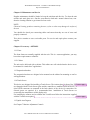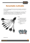
1
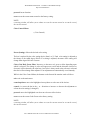
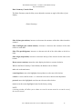
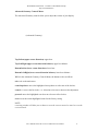
Jakob Hatteland Instrument – a member of The Hatteland Group http:/www.hatteland.no User’s Manual PRELIMINARY 17 inch Industrial Color Monitor JH 17C03 P75 based on the NEC MultiSync P750 Document: Order no: Issued by: User’s Manual UM 17C03 P75 Jakob Hatteland Instrument AS Jakob Hatteland Instrument AS JH 17C03 P75 User’s Manual User’s Manual for the JH 17C03 P75 Industrial Color Monitor 1 Jakob Hatteland Instrument – a member of The Hatteland Group http:/www.hatteland.no Document: Revision: Order no: Issued by: for Product: Type: User’s Manual 9701 UM 17C03 P75 V1.0 Jakob Hatteland Instrument A/S 17 inch Industrial Color Monitor JH 17C03 P75 Table of Contents Chapter 1 General 1.1 Introduction to JHI monitors 1.2 About this manual 1.3 General Description of the JH 17C03 P75 1.4 The JHI industrial CRT’s and TFT’s 1.5 Registered trademarks Chapter 2 Approvals 2.1 CE 2.2 Declaration of Conformity 2.3 Type Approvals 2.4 IACS E10 2.5 IEC 945 3rd. 2.6 Compass Safe Distance Chapter 3 Precautions 3.1 Unpacking 3.2 Mounting 3.3 Recommended use 3.4 Virus Chapter 4 Mounting Instructions 4.1 Rack version 4.2 Recommended binding screws 4.3 Mounting holes Chapter 5 Hook Up 5.1 Power cable 5.2 Signal cable 5.3 Input signals 5.4 Video input Chapter 6 Connection 6.1 Connection alternatives 6.2 Connection to PC 6.3 Connection to Mac 6.4 Connection to Video cards User’s Manual for the JH 17C03 P75 Industrial Color Monitor 2 Jakob Hatteland Instrument – a member of The Hatteland Group http:/www.hatteland.no 6.5 Connection to cards using BNC 6.6 Connection to two systems or Video cards Chapter 7 Monitor Adjustment Control 7.1 Outside front panel controls 7.2 Inside front panel controls 7.3 On Screen Manager elements Chapter 8 Trouble Shooting 8.1 General 8.2 Symptoms and cure Chapter 9 Technical Specification and drawings 9.1 Technical description 9.2 Mechanical drawing Chapter 10 Tables - Pin assignment and timing 10.1 Pin assignment table - Video Input 10.2 BNC Input 10.3 Multicable’s Pin assignment 10.4 Serial Port 10.5 Signal Timing Chart 10.6 Preset Timing Chart Chapter 11 Maintenance and Service Chapter 12 Accessory - OPTIONS 10.1 Front 10.2 Cabinet 10.3 Suspension brackets 10.4 Touch Screen 10.5 Quick Auto Degauss Chapter 13 Users own notes User’s Manual for the JH 17C03 P75 Industrial Color Monitor 3 Jakob Hatteland Instrument – a member of The Hatteland Group http:/www.hatteland.no Chapter 1 General 1.1 Introduction to JHI monitors JHI is one of the leading producers of maritime & industrial monitors in the market. Our industrial color monitor provides you with the latest in technology. This means that the monitor provides you with automatic compatibility with multiple operating platforms and a vast array of graphics standards allowing resolution upgrades without upgrading the monitor. The high quality of the monitors allows you to display professional applications with clarity and enhanced color and image quality. Options are rack version for flush mounting and the cabinet version for “stand alone” applications. Custom designed front, color and logo can easily be adapted. 1.2 About this manual This manual contains information needed for installation, power up and use of the monitor JH 17C03 P75. The manual contains also electrical, mechanical and inputs signal specifications. All specifications in this manual, due to manufacturing, new revisions and approvals, are subject to change without notice. It is recommended that installation engineer and user of the display unit read this manual before installation and use. NB! This manual or parts of it must not be reproduced or copied without written permission from the manufacturer - Jakob Hatteland Instrument AS 1.3 General description of the JH 17C03 P75 The color monitor described in this manual are an industrialized version of high quality products. The monitors allow you to display professional applications with clarity and enhanced color and image quality. The combinations of the monitors plug and play capability, high quality picture and the hardware construction of the mechanical parts and assembly will satisfy a wide range of maritime & industrial environments. 1.4 The JHI industrial CRT’s and TFT’s The JHI industrial CRT monitors and TFT displays offers the high-tech industry a complete range of units. Jakob Hatteland Instrument has developed and produced industrial monitors since 1987. All the units are stand alone CE approved units. A number of the products are also Type Approved by several of the major classification societies. 1.5 Registered trademarks IBM PC/XT/AT, PS/2, MCGA, VGA 8514/A and XGA are registered trademarks of International Business Machines Corporation. Apple and Macintosh are registered trademarks of Apple Computer Inc. Microsoft and Windown are registered trademarks of the Microsoft Corporation. NEC is a registered trademark of NEC Corporation. User’s Manual for the JH 17C03 P75 Industrial Color Monitor 4 Jakob Hatteland Instrument – a member of The Hatteland Group http:/www.hatteland.no ErgoDesign is a registered trademark of NEC Home Electronics, Ltd. In U.K., Germany, France, Spain, Italy, Denmark, Norway, Sweden and Benelux. CROMACLEAR is a trademark of NEC Home Electronic, Ltd. In U.K., Germany, France, Spain, Italy, Sweden and Benelux. MultiSync is a registered trademark of NEC Technologies, Inc in U.S. and of NEC Home Electronics, Ltd in Canada, U.K., Germany, France, Spain, Italy, Austria, Benelux, Switzerland, Denmark, Finland, Norway and Saudi Arabia. All other trademarks or registered trademarks are property of their respective owners. Chapter 2 Approvals 2.1 CE This product is partly tested according to the regulations according to the EMC directive and found to be within the requirements given. Jakob Hatteland Instrument AS declares that this product is in conformity according to information given in chapter 2.2 Declaration of Conformity. 2.2 Declaration of Conformity (Declaration of Conformity) User’s Manual for the JH 17C03 P75 Industrial Color Monitor 5 Jakob Hatteland Instrument – a member of The Hatteland Group http:/www.hatteland.no 2.4 Type Approvals This product is tested according to the E10 test specification issued by the International Association of Classification Societies. The E10 are a unified test specification and in accordance with the requirements for the environmental tests specified in the Society’s Rules. Approvals by the classification societies are based on the E10 test specifications. Farther the products are tested according the IEC 945 3rd. edition. This product is approved by the following Type Approval Societies: DNV LRS ClassNK GL Det Norske Veritas Lloyd’s Register of Shipping Nippon Kaiji Kyokai Germanischer Lloyd 2.4 IACS E10 The E10 test specification is issued by the International Association of Classification Societies. The specification covers a unified environmental test specification for testing procedure for electrical, control and instrumentation equipment, marine computers and peripherals covered by classification. The aim of testing are to demonstrate the ability of the equipment to function as intended under the testing conditions. 2.5 IEC 945 3rd. The IEC 945 3rd. test are used to test equipment meant for navigation in marine environments. The test covers the conducted emission on power leads and the interference level on radiated electromagnetic fields. 2.6 Compass Safe Distance The monitor is tested both in normal horizontal (vertical screen) mounting configuration and in vertical (horizontal screen) mounting configuration. Compass safe distance = 160 cm (vertical screen) Compass safe distance = 175 cm (horizontal screen) Chapter 3 Precautions 3.1 Unpacking Handle with care when transporting the monitor. Do not unpack the monitor before it is on the site of use or installation. If you are not using a mechanical lifting device you should have somebody to help you when unpacking the installing the monitor. This is a heavy device and you may cause damage to yourselves of other persons of you lose the grip. It is recommended that you save the original box and packing materials for transportation or shipment of this monitor. User’s Manual for the JH 17C03 P75 Industrial Color Monitor 6 Jakob Hatteland Instrument – a member of The Hatteland Group http:/www.hatteland.no 3.2 Mounting Ensure prior to installation that your mounting jig, console or other application are capable of carrying the monitor. All mounting screws applicable both in the front and in the back of the monitor should be used for fastening the device. Also ensure that your fastening threads fits properly to the enclosed fastening screws. 3.3 recommended use For optimum performance when setting up and using the monitor please note the following: The optimum monitor position is away from direct sunlight. Install the monitor just below eye level for the ideal viewing angle. Allow adequate ventilation around the monitor so that heat can properly dissipate. We recommend to adjust the brightness in a way that the background raster disappears. For ergonomically reasons we recommend not to use the position of the maximum contrast control. the preset size and position when using standard signals preset color and preset distortion using non-interlaced signals with a vertical refresh rate between 75 - 160 Hz. 3.4 Virus The feature “Intelligent Power Manager System” IPM are enclosed on a 3,5” diskette. Before installing the program from the disk you should READ THIS: The enclosed disk is thoroughly checked for viruses. While every care is taken neither JHI nor the producer of the diskette will accepts no responsibility for loss or damage occurred during installation or use of the content on the diskette. You are strongly advised to have recent, verified backups of your system files before installing new software. We further advise you to check the diskette according to your own safety standards (anti virus check). Chapter 5 Hook Up 5.1 Connecting Power Ensure that the device are switched off prior to power hook up. Check your power source to ensure that correct voltage are present. This device are equipped with an universal power supply and need the following mains voltage to operate; Input voltage: AC 100 - 120 V 50/60 Hz or AC 220 - 240 V 50/60 Hz User’s Manual for the JH 17C03 P75 Industrial Color Monitor 7 Jakob Hatteland Instrument – a member of The Hatteland Group http:/www.hatteland.no Power cons. : 145 W Interface: Std. instr.. AC socket We recommend that you use the power cord supplied with the monitor for hook up. 5.2 Signal cable Ensure that the device are switched off prior to interface hook up. Check your interface source to ensure that the right signals are present. Check out the tables with signal and timing if you are unfamiliar with the signals. 5.3 Input signals This monitor will apply to most known PC and Workstation signals. Hook up to your device should normally cause no problem. See Chapter 6 Connection to computer for different connection options. For more details regarding Pin Assignment Table, Signal Timing Charts or Preset Timing Chart please turn to Chapter 10 Tables - Pin assignment and timing. 5.4 Video input The video input can be done through the D-SUB connectors or the BNC connectors located at the back of the monitor: 1 x Mini D-SUB 15p female connector 1 x D-SUB 15p female connector 5 x BNC connector NB! Always ensure that connected signal cables are properly mounted and that screw coupling are used. This will ensure that the signal cable always are connected. Chapter 6 Connection 6.1 Connection alternatives There are several options for connecting this monitor to your computer. Depending on your equipment and computer capability use one of the options below. All options are available for hook up and are located at the back side of the monitor. 6.2 Connection to PC This monitor comply with most common known PC computers. Your system has one of two configurations: 1. The video controller is built into the computer 2. The video controller is in the form of a video card (sometime referred to as a graphic card, video adapter, or graphics board.) User’s Manual for the JH 17C03 P75 Industrial Color Monitor 8 Jakob Hatteland Instrument – a member of The Hatteland Group http:/www.hatteland.no Both configurations have a video connector (or a CRT port). If you are not sure as to which connectors is the video connector, consult your computer or video card manual. To attach the monitor to your system, follow the instructions below. 1. Turn off the power to the monitor and computer. 2. If necessary, install the video card. For more information, refer to the manual accompanying the card. 3. Make sure the BNC/D-SUB switch behind the controller hatch in front of the monitor is set to the D-SUB down position. 4. Connect the 15-pin mini D-SUB end of the MultiCable to the video connector of your system. 5. Connect the 15-pin D-SUB end of the MultiCable to the monitor. 6. Connect one end of the power cable to the monitor and the other end to the power outlet. 7. Turn on the monitor and computer. 8. This completes the installation. 6.3 Connecting to Mac This monitor comply with most Mac computers. Your system has one of two configurations: 1. The video controller is built into the computer. 2. The video controller is in the form of a video card (sometimes referred to as a graphic card, video adapter, or graphics board) installed in a Nu-Bus or PDS slot. Both configurations have a video connector. If you are not sure as to which connector is the video connector, consult your computer or video card manual. To attach the monitor to your system, follow the instructions below. 1. Turn off the power to the monitor and computer. 2. If necessary, install the video card. For more information, refer to the manual accompanying the card. 3. Check the SYNC switch on the back of the monitor. The ON/OFF switch have different use on some of the Mac models. 4. Make sure the BNC/D-SUB switch behind the controller hatch in front of the monitor is set to the D-SUB down position. 5. Connect the 15-pin mini D-SUB end of the MultiCable to the video connector of your system. 6. Connect the 15-pin D-SUB end of the MultiCable to the monitor. 7. Connect one end of the power cable to the monitor and the other end to the power outlet. 8. Turn on the monitor and computer. 9. This completes the installation. NB! Some Mac computers require a cable adapter, consult your dealer. 6.4 Connection to Video cards User’s Manual for the JH 17C03 P75 Industrial Color Monitor 9 Jakob Hatteland Instrument – a member of The Hatteland Group http:/www.hatteland.no If your computer or video card is not compatible with the monitors preset signals or has a different pin assignment, refer to the steps below to determine if your system is compatible with the monitor. 1. 2. 3. 4. 5. 6. 7. 8. 9. Turn off the power of the monitor and the computer. Determine the video connector’s pin assignment of your video card. Determine the output signal timing and level of your video card. Check the pin assignment and signal timing charts of the video card and make sure the monitor accepts these pin assignments and signal timings. Connect the signal cable supplied with your video card to the monitor. Connect on end of the power cable to the monitor and the other end to a power outlet. Turn on the monitor and computer. Adjust size and position of the image to your preference. This completes the installation. 6.5 Connecting to cards using BNC The monitor also complements high resolution graphics cards or systems. To attach the monitor to your system, follow the instructions below. 1. Turn off the power to the monitor and computer. 2. If necessary, install the video card. For more information refer to the manual accompanying the card. 3. Make sure the BNC/D-SUB switch behind the controller hatch in front of the monitor is set to the D-SUB up (raised) position. 4. Connect the D-SUB (or the appropriate connector) end of the video cable supplied with the graphics card to the connector of the video card. 5. Connect the red BNC cable to the BNC connector of the monitor marked R. The green BNC cable should be connected to the BNC connector of the monitor marked G. The blue BNC cable should be connected the BNC connector of the monitor marked B. If you have a fourth BNC connector (composite SYNC) connect it to the BNC connector on the monitor marked HS/CS. If you have a fifth BNC connector (vertical SYNC) connect it to the BNC connector on the monitor marked VS. 6. Connect one end of the power cable to the monitor and the other end to the power outlet. 7. Turn on the monitor and the computer. 8. This completes the installation. 6.6 Connection to two systems or Video card The monitor are designed to support connection to two systems or video cards simultaneously. This feature allows you to use one monitor for two systems and easily select between the two with the front panel BNC/D-SUB switch. This configuration requires one of the systems to be connected using BNC connectors. To attach the monitor to two systems, follow the instructions below. 1. Follow the installation guidelines you find on the pages before how to connect with a MultiCable. User’s Manual for the JH 17C03 P75 Industrial Color Monitor 10 Jakob Hatteland Instrument – a member of The Hatteland Group http:/www.hatteland.no 2. Follow the installation guidelines you find on the pages before how to connect with BNC cable . 3. Turn on the monitor and both systems. 4. This completes the installation. 5. Use the BNC/D-SUB which on the front panel of the monitor to switch between the systems. Chapter 7 Monitor Adjustment Controls 7.1 Outside front panel controls This monitor is provided with easy access main control for the user. On the monitors front right side following controls are available; Adjustment/control items ON/OFF power switch Function/description - turns the monitor power on or off. When the power is on, the LED is lit. Degauss switch -eliminates the build-up of stray magnetic fields which alter the correct scan of the electron beams and affect the purity of the screen colors, focus and convergence. CONT - adjust the image brightness in relation to the background. BRIGHT - adjust the overall image and background screen brightness. LED (Power Indicator Light) - located top left of the power switch is on and indicates the monitor’s power mode. Each mode reduces the amount of power used by the monitor. 7.2 Inside front panel controls Inside the front panel at the left side of the monitor the so called OSM controls are available. The On Screen Manager system offers the ultimate form of monitor controls. The adjustments allow you to navigate through menus and adjust controls. As you choose controls, the moving icon shows you what the chosen control will do. These pictures give you immediate understanding of the controls. OSM controls include the following extended controls: Size, Position, Basic and Advanced Geometry, Enhanced Color Control and other OSM utilities. Adjustments are saved instantly. The currently addressed control can be reset to factory settings by pressing the reset button. Fig. 7.2.1 Inside front panel controls User’s Manual for the JH 17C03 P75 Industrial Color Monitor 11 Jakob Hatteland Instrument – a member of The Hatteland Group http:/www.hatteland.no Adjustment/control items EXIT Function/description - in the main menu: exits the OSM controls in a sub menu: exits to the main menu CONTROL UP/DOWN - moves the highlighted area up/down to select one of the controls. CONTROL +/- - in the main menu: no function - in a sub menu: moves the bar in the + or - direction to increase or decrease the adjustment. PROCEED - in the main menu: proceeds to the selected menu choice (indicated by the highlighted area). - in a sub menu: proceeds to the control in that sub menu. RESET resets the currently highlighted control to the factory settings: - in the main menu: resets all the controls within the highlighted sub menu. - in a sub menu: reset the highlighted control. NOTE: When pressed, a warning window will appear allowing you to cancel the reset function. D-SUB/BNC - Selecting your input signal either from D-SUB or RGB Power LED Adjust - allows you to adjust the light intensity of the power LED at the front of the device. (See LED chapter 7.1). AUTO DEGAUSS - this is an OPTION feature. With the adjustment you can select a QUICK AUTO DEGAUSS with interval from 30 sec. to 30 min. When activated front panel degauss button are disabled. When deactivated, OFF position, the front panel degauss button are activated. NOTE: With the AUTO DEGAUSS option the degauss function will be a QUICK degauss. The elapsed time from start to end will be 0,2 sec. The fastest interval between quick degauss are 30 sec. Without AUTO DEGAUSS option the degauss will take about 2,0 sec from start to end. You should not press the degauss switch for more than 10 seconds. Please also allow a minimum of 20 minutes to elapse between uses of the degauss button if AUTO DEGAUSS not are installed (see above). User’s Manual for the JH 17C03 P75 Industrial Color Monitor 12 Jakob Hatteland Instrument – a member of The Hatteland Group http:/www.hatteland.no 7.3 On Screen Manager elements Typical OSM windows have the following elements: highlighted: indicates the selected menu control moving icon: provides a quick moving illustration of what the control will do (also indicates the direction of control when adjusting) ( )( ) scroll bar: ( ) indicates direction of adjustment (Scroll bar) numeric reading: provides a number to remember, record or compare with a specific setting. Accessing OSM Press any of the control buttons, +,-, arrow up, arrow down, or the proceed button. Turning off OSM When in the main menu: press the exit button once. When in sub menus: press the exit button twice. OSM Menus Main Menu On Screen manager’s main menu of control gives you an overview of the selection of controls available. (On Screen Manager) The arrows in the bottom or upper right corners indicates further choices are available. Use the Up or Down control buttons to scroll through all of the options. User’s Manual for the JH 17C03 P75 Industrial Color Monitor 13 Jakob Hatteland Instrument – a member of The Hatteland Group http:/www.hatteland.no While in the Main Menu, the buttons works as follows: exit: exits the OSM controls control up/down: moves the highlighted area up/down to select one of the choices. control: +/-: no function proceed: proceeds to the selected menu choice. reset: resets all the controls within the highlighted sub menu. NOTE: resetting the Color Control menu resets all of the color setting. The reset function is not needed in the OSM Turn Off Time and Language Select menus. Position Menu (Position) Up/Down: moves the image vertically up or down. Right/Left: moves the image horizontally left of right. Size Menu (Size) Tall/Short: increases or decreases the vertical size of the image. Narrow/Wide: increase or decrease the horizontal size of the image. While in the position/Size Controls Menu, the buttons will work as follows: exit: exits to the main menu. Control up/down: refer to UP/Down and Tall/Short. Control +/-: refers to Left/Right and Narrow/Wide. User’s Manual for the JH 17C03 P75 Industrial Color Monitor 14 Jakob Hatteland Instrument – a member of The Hatteland Group http:/www.hatteland.no proceed: has no function reset: resets the current menu control to the factory setting. NOTE: a warning window will allow you to choose to reset the current control or to cancel reset of the current control. Color Control Menu ( Color Control) Preset (Setting): Selects the desired color setting. The bar is replaced by the color setting choice (from 1 to 5). Each color setting is adjusted at the factory to the stated degree Kelvin. If a setting is adjusted, the name of the setting will change from degree Kelvin to Custom. Color Gain Red, Green, Blue: Increases or decreases red, green or blue depending upon which is selected. The change in color will appear on screen and the direction (increase or decrease) will be shown by the color bars. One color is always used as the reference color and therefore will not change when adjusted. Your adjustment are automatically saved instantly. While in the Color Control Menu, the buttons on the front of the monitor work as follows: exit: exits to the main menu. control up/down: moves the highlighted area up/down to select one of the choices. control +/-: moves the bar in the + or - direction to increase or decrease the adjustment or selects the color setting (1 through 5). proceed: moves the highlighted area down to select one of the choices. reset: resets the current Color Preset to the factory setting. NOTE: a warning window will allow you to choose to reset the current control or to cancel reset of the current control. User’s Manual for the JH 17C03 P75 Industrial Color Monitor 15 Jakob Hatteland Instrument – a member of The Hatteland Group http:/www.hatteland.no Basic Geometry Controls Menu The Basic Geometry controls allow you to adjust the curvature or angle of the sides of your display. (Basic Geometry) Sides In/Out (pin cushion): increases or decreases the curvature of the sides either inward or outward. Sides Left/Right (pin cushion balance): increases or decreases the curvature of the sides relative to each other. Sides Tilt (parallelogram): increases or decreases the tilt of the sides either to the left or right. Sides Align (trapezoidal): increases or decreases the top of the screen to be the same as the bottom. Rotate (raster rotation): rotates the entire display clockwise or counter clockwise. While in the Basic Geometry Controls Menu, the buttons work as follows: exit: exits to the main menu control up/down: moves the highlighted area up/down to select one of the choices. control +/-: moves the bar in the + or - direction to increase or decrease the adjustment. proceed: moves the highlighted area down to select one of the choices. reset: resets the current highlighted control to the factory setting. NOTE: a warning window will allow you to choose to reset the current control or to cancel reset of the current control. User’s Manual for the JH 17C03 P75 Industrial Color Monitor 16 Jakob Hatteland Instrument – a member of The Hatteland Group http:/www.hatteland.no Advanced Geometry Controls Menu The Advanced Geometry controls allow you to adjust the corners of your display. (Advanced Geometry) Top In/Out (upper corner distortion): upper bow Top Left/Right (upper corner distortion balance): upper bow balance. Bottom In/Out (lower corner distortion): lower bow. Bottom Left/Right (lower corner distortion balance): lower bow balance. While in the Advanced Geometry Controls Menu, the buttons works as follows: exit: exits to the main menu control up/down: moves the highlighted area up/down to select one of the choices. control +/-: moves the bar in the + or - direction to increase or decrease the adjustment. proceed: moves the highlighted area down to select one of the choices. reset: resets the current highlighted control to the factory setting. NOTE: a warning window will allow you to choose to reset the current control or cancel to reset the current control. User’s Manual for the JH 17C03 P75 Industrial Color Monitor 17 Jakob Hatteland Instrument – a member of The Hatteland Group http:/www.hatteland.no OSM Location Menu You can choose where you would like the OSM image to appear on the screen. Selecting OSM Location allows you to manually adjust the OSM Menu left, right, up or down. (OSM Location) OSM Turn Off Time Menu The OSM menu will stay on as long as it is in use. In the OSM Turn Off Time Menu, you can select how long the monitor waits after the last touch of a button to shut off the OSM menu. The preset choices are 10, 20, 30, 60 and 120 seconds. (OSM Turn Off Time) Display Mode Menu Display Mode provides you information about the current resolution display and technical data including the horizontal and veritcal frequency. (Display Mode) Note: If the Mode indicates the symbol “(!)”, the reset function for Position and Size are not effective. Language Select Menu OSM Menus are available in six languages. User’s Manual for the JH 17C03 P75 Industrial Color Monitor 18 Jakob Hatteland Instrument – a member of The Hatteland Group http:/www.hatteland.no Vertical Linearity Menu The vertical linearity controls allow you to adjust the spacing of the areas on the screen. The object of this control is to ensure that a one-inch circle is a true one-inch circle wherever it is drawn on the screen (same image size throughout the total screen area). (Vertical Linearity) The best way to determine the vertical linearity is as shown in the Vertical Linearity Menu. Draw equally spaced (as determined by a drawing application that has a ruler) horizontal lines across you screen. Using the Center control allows you to adjust the spacing between the center lines, and using the Bottom/Top control allows you to adjust the spacing between the top and bottom lines. Factory Preset Selecting Factory Preset allows you to reset all OSM settings back to the factory settings. The following warning statement will appear to confirm that you do want to reset ALL settings. Individual settings can be reset by highlighting the control to be reset and pressing the RESET button. (WARNING) Self Test To make sure, that your monitor is working well, you can choose the Self Test function in the following way: Power down you monitor and your computer. Power on the monitor. While the Exit button is held down, press the Proceed button. The following picture is shown on the monitor. (see below). If you do not press the Exit button to cancel the Self Test function, the monitor will show a dark screen within 20 seconds. (Self Test Menu) User’s Manual for the JH 17C03 P75 Industrial Color Monitor 19 Jakob Hatteland Instrument – a member of The Hatteland Group http:/www.hatteland.no Chapter 8 Trouble Shooting 8.1 General If for some reason there should be something wrong check the symptoms carefully and try to cure it with the hints below. Also check out chapter 5 and 6. The cure may be at your hands! 8.2 Symptoms and cure No picture Power Switch and computer power switch should be in the ON position. MultiSync signal cable should be completely connected to the video card/computer. The video card must be completely seated in the slot. Check the connector for bent or pushed-in pins. Image is scrolling or unstable Signal cable may not be completely connected to the computer. Check the pin assignments and signal timings of the monitor and your video card with respect to recommended timing and pin assignments. Check for proper connection or make sure that the video card is computer compatible and that the card is properly seated in the computer. Check SYNC Switch for its correct position. LED on the monitor is not lit or lit with orange or yellow color Power switch should be in the ON position and the power cord should be connected. Make certain the computer is not in a power saving mode (touch keyboard or mouse). Picture is fuzzy Adjust the Contrast or Brightness controls. Push the Degauss button to demagnetize the tube. Picture bounces or a waving pattern is present in the picture Move electrical devices that may be causing electrical interference away from the monitor Edges of the display image are not square Use the OSM Basic and Advanced Geometry Controls to straighten the edges. Display image is not centered, is too small, or too large Adjust Size and Position Controls to adjust the image in the OSM. Picture has a green tint or the background brightness cannot be turned down Check the Sync Switch is in the proper position. Disconnect the C/S input of the BNC cable if you are using the BNC inputs. Color looks blotchy Press the Degauss button. Color is incorrect or background brightness is too high and cannot be decreased. The Sync Switch should be in the correct position. No green color (if using BNC connection) User’s Manual for the JH 17C03 P75 Industrial Color Monitor 20 Jakob Hatteland Instrument – a member of The Hatteland Group http:/www.hatteland.no Check the BNC cables for proper connection. G and CS connection may be reversed. Chapter 9 Technical Specification and drawing 9.1 Technical description Picture Tube 41 cm flat square CRT, 15,6 visual inches. 0.28 mm Trio dot pitch Dot type black matrix. Medium-short persistence phosphor, dark bulb, glass with multi-layered anti-static coating. Input Signal Video: Analog 0.7 Vp-p 75 Ohm Positive Sync: Separate sync. Horizontal sync. Vertical sync. Composite sync. Sync. On Green TTL Level Positive/Negative Positive/Negative TTL Level Positive/Negative (0.3 Vp-p) Negative Display Colors: Analog Input: Unlimited colors (Depends on the graphics board used) Synchronisation Range: Horizontal 31 kHz to 82 kHz (Automatically) Vertical 55 to 160 Hz (Automatically) Resolution: Video Band Width: Horizontal 1280 dots (non interlaced) Vertical 1024 lines (non interlaced) 140 MHz BNC input Active Display Horizontal 306 mm Area (factory Vertical 230 mm setting) (Active display area is dependent upon the signal timing) Active Display Horizontal 316 mm Area (full scan) Vertical 237 mm Rated Voltage AC 100 - 120 V 50/60 Hz AC 220 - 240 V 50/60 Hz Power cons. 145 W Environmental considerations: Operating: Temperature 0 deg. C to + 55 deg. C Humidity 30 % to 80 % (non condensing) Storage: Temperature -20 deg. C to + 60 deg. C Humidity 10 % to 60 % (non condensing) User’s Manual for the JH 17C03 P75 Industrial Color Monitor 21 Jakob Hatteland Instrument – a member of The Hatteland Group http:/www.hatteland.no Weight: 33 kg 9.2 Technical drawing User’s Manual for the JH 17C03 P75 Industrial Color Monitor 22 Jakob Hatteland Instrument – a member of The Hatteland Group http:/www.hatteland.no Chapter 10 Tables - Pin Assignment and Timing 10.1 Pin assignment table - Video Input 10.2 BNC Input User’s Manual for the JH 17C03 P75 Industrial Color Monitor 23 Jakob Hatteland Instrument – a member of The Hatteland Group http:/www.hatteland.no 10.3 Multicable’s Pin assignment 10.4 Serial port 10.5 Signal Timing Chart User’s Manual for the JH 17C03 P75 Industrial Color Monitor 24 Jakob Hatteland Instrument – a member of The Hatteland Group http:/www.hatteland.no 10.6 Preset Timing Chart User’s Manual for the JH 17C03 P75 Industrial Color Monitor 25 Jakob Hatteland Instrument – a member of The Hatteland Group http:/www.hatteland.no Chapter 11 Maintenance and Service Regular maintenance should be limited to keep the unit dust and dirt free. To clean the unit and the anti static glass use a lint-free, non-abrasive cloth and a neutral cleaner base, nonabrasive cleaning solution or gas cleaner for best result. NOTE: Chemical cleaning products containing benzene, xylene or other may damage the surface of the unit. You should also check your connecting cables and ensure that they are out of stress and properly connected. This device contains no user serviceable parts. For service and repair please contact your supplier. Chapter 12 Accessory - OPTIONS 11.1. Front The front frame are normally supplied with the unit. This is a custom application, you may have other requirements or solutions. 11.2. Cabinet The unit can be delivered with a cabinet. This cabinet are well suited when the device are to be mounted in “stand-alone” applications. 11.3 Suspension brackets The suspension brackets are designed to be mounted on the cabinet for mounting on roof or wall applications. 11.4 Touch Screen This device are designed for installing a Touch Screen. The Amiran glass in front of the TFTComment [BQ1]: are changed with the Touch Screen glass and the controller are mounted inside the device. A 9pin D-SUB connector are mounted in the back chassis of the device for connection. No external power are required. It is recommended that installation of Touch Screen are executed by the manufacturer of this display unit. For installing the software and to calibrate the Touch Screen follow the instructions supplied Comment [BQ2]: with the Touch Screen option. 11.5 Quick Auto Degauss See Chapter 7 Monitor Adjustment Controls User’s Manual for the JH 17C03 P75 Industrial Color Monitor 26 Jakob Hatteland Instrument – a member of The Hatteland Group http:/www.hatteland.no Chapter 13 Users own notes User’s Manual for the JH 17C03 P75 Industrial Color Monitor 27