1
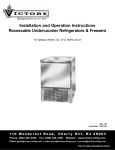
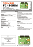
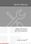
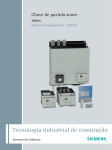
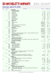
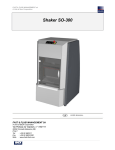
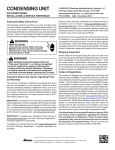
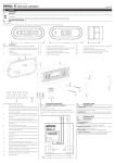
DOC D133X1
Full Example of ReFreeX™ Method
1. Content
1.
2.
Content
Introduction
2.1. What is ReFreeX™?
2.2. What is this example about?
2.3. Disclaimer
3.
The application
3.1. Usage
3.2. Main specification
3.3. The ReFreeX refrigeration circuit
3.4. Full specification
3.5. Attachment list
3.6. Cross reference
4.
Patents, marks and contacts
4.1. Patents
4.2. Marks
4.3. Contacts
2. Introduction
2.1. What is ReFreeX™?
It is a new and improved refrigeration method described elsewhere in the document D133V and D133W.
2.2. What is this example about?
This is a full example of a modern refrigeration plant built with the ReFreeX technology.
This example is meant to be understood by an experienced designer of refrigeration plants.
2.3. Disclaimer
The information herein provided is believed to be accurate and this specific refrigeration plant has been successfully
installed and tested like several other similar plants but nor the author nor the company Micheletti Impianti do assume any
responsibility for the information herein provided. This is a guidance example for expert designers of refrigeration plants to
be used under their own responsibility with any eventual modification that can be required. Local regulation may impose
different or additional safety devices.
3. The application
3.1. Usage
The refrigeration plant is to be used in a cold room for frozen food storage at –25° C.
3.2. Main specification
The refrigeration plant has a 30 hp compressor, air condensation and R404A refrigerant. Nominal cooling capacity is
9350 watt at –35° C evaporation and +45° C condensation.
3.3. The ReFreeX refrigeration circuit
The ReFreeX™ refrigeration system is a dry-expansion refrigeration system and includes a compressor, a condenser
coil, and an evaporator coil. No liquid receiver is installed and no thermostatic valve is provided. Expansion is performed
in the piping connecting the condenser to the evaporator. Regulation is performed by a plain solenoid valve, periodically
pulsed on and off.
3.4. Full specification
Full specification is provided in the attached part list and in the other attached drawings.
Part list omits small components and complements like
eb / c17 / from M181C1 20.10.1997 / doc code in the header / file D133X1_Rev_01.doc / last saving 13.04.2006 - page 1/2
DOC D133X1
•
•
•
•
•
•
•
•
anchors
fixings
fittings
bends
siphons
soldering alloy
evaporator drain
wiring materials
3.5. Attachment list
•
•
•
•
•
•
attachment 1: part list
attachment 2: circuit drawing
attachment 3: electric board
attachment 4: electric plant
attachment 5: controller wiring
attachment 6: user manual
3.6. Cross reference
•
•
doc D133V - ReFreeX Refrigeration Method: an explanation of method and principles
doc D133W - Economical Analysis of ReFreeX Method: cost comparison versus the traditional method
4. Patents, marks and contacts
4.1. Patents
European patent nr. 04425426.6 is pending.
USA patent nr. US10/956,297 is pending.
PCT patent deposited with international application number PCT/IT/2005/000268.
4.2. Marks
ReFreeX USA mark application filed with serial nr. 78509794 .
4.3. Contacts
Please contact
Micheletti Impianti
C.ne Appia, 33
00179 Roma
Italy
www.micheletti.org
Mr. Emidio Barsanti
Phone nr. +39 06 7883363
Fax nr. +39 06 789716
E-mail [email protected]
eb / c17 / from M181C1 20.10.1997 / doc code in the header / file D133X1_Rev_01.doc / last saving 13.04.2006 - page 2/2
Part list - attachment
nr. 1 of doc D133X1
Code
Component
Qty Unit
Description
252
compressor
1
pc
Bitzer 4G-30.2Y - 30 hp - 84.5 m3/h - semi-hermetic reciprocating compressor
208
crankcase oil heater
1
pc
Bitzer 140 w oil heater
522
mc electric box heater
1
pc
heating cable - 50 cm - 30 ohm - 12 V - 5 w
214
vibration isolator
1
pc
vibration isolator D22 mm
215
vibration isolator
1
pc
vibration isolator D42 mm
472
oil probe
1
pc
0...30 bar - 4...20 mA pressure probe
470
lp probe
1
pc
0...30 bar - 4...20 mA pressure probe
471
hp probe
1
pc
0...30 bar - 4...20 mA pressure probe
466
suction temp probe
1
pc
ntc ss141 25°C 10kohm 1% stainless case - 3m silicon cable (standard ntc)
467
discharge temp probe
1
pc
ntc ss141 25°C 10kohm 1% stainless case - 3m silicon cable (standard ntc)
473
fixed hp switch
1
pc
Danfoss-Saginomyia mini pressure switch ACB 28/21 bar
235
discharge line
15
m
copper piping D22x1 mm
201
condenser
1
pc
LU-VE SHVN 38/1 - phi 2x2x350mm - 36.4 kw at dT=15K
468
condenser air temp probe
1
pc
ntc ss141 25°C 10kohm 1% stainless case - 3m silicon cable (standard ntc)
531
liquid line from condenser
15
m
copper piping D12x1 mm
481
liquid line shut-off
1
pc
ball shut-off D12 mm
218
filter drier
1
pc
Danfoss DML84S D12 mm - drying 8g H2O at +52°C and 30ppm
219
sight glass
1
pc
Danfoss SGN12S D12 mm - showing H2O at 25...100 ppm
247
liquid solenoid valve body
1
pc
EVR6 NC D12 - min dp=0.05 bar - kv=0.8 m3/ h of H2O at dp=1 bar
248
liquid solenoid valve coil
1
pc
Danfoss coil NC 230 V-50 Hz-10 w-21 VA - IP67 - 1 m cable
483
liquid/hot gas shut-off
1
pc
ball shut-off D16 mm
482
hot gas shut-off
1
pc
ball shut-off D16 mm
264
hot gas solenoid valve body
1
pc
Danfoss EVR10 NC D16 - min dp=0.05 bar - kv=1.9 m3/ h of H2O at dp=1 bar
265
hot gas solenoid valve coil
1
pc
Danfoss coil NC 230 V-50 Hz-10 w-21 VA - IP67 - 1 m cable
484
liquid/hot gas line
30
m
copper piping D16 mm
485
liquid/hot gas line insulation
30
m
armaflex-like mm 16 x 9
527
refrigerant net filter
1
pc
Y filter - D16 mm
224
evaporator without defrost
1
pc
LU-VE S3HC 284 N80 - phi 4x350mm - 15.8 kw dry at TC=0° C and dT1=8K
512
evaporator drain tray heater
3
pc
heating cable - 10 m - 650 ohm - 230 V - 80 w
464
room air temp probe
1
pc
ntc ss141 25°C 10kohm 1% stainless case - 3m silicon cable (standard ntc)
465
defrost temp probe
1
pc
ntc ss141 25°C 10kohm 1% stainless case - 3m silicon cable (standard ntc)
233
suction line
30
m
copper piping D42x1 mm
234
suction line insulation
30
m
armaflex-like mm 42 x 13
237
refrigerant gas
4
kg
R404A refrigerant
238
lubricating oil
-
kg
ester oil already present in the compressor crankcase
232
electric board
1
pc
30 hp ReFreeX electric board
461
master controller
1
pc
ReFreeX master controller
460
slave controller (mc side)
1
pc
ReFreeX slave controller
460
slave controller (room side)
1
pc
ReFreeX slave controller
475
door limit switch
1
pc
metal case limit switch with adjustable wheel arm
Rif eb/c17/m187v5/2006-04-13/d133x1_att_01.xls - pag. 1/ 1
doc
H206F5 revnr.
01 2
Attachment
date: 2006-03-10 - author: eb - location: c17
of doc D133X1
SCHEMA FRIGORIFERO MICRO SBR GAS CALDO
REFRIGERATING CIRCUIT - HOT GAS DEFR - MICRO
max 3m
Room ceiling
Soffitto cella
527
224
465
Sonda sul tubo aspirante alle ore 6.
Suction pipe probe located at 6 o'clock.
234
max 3m
464
Sonda in aria dietro al condensatore.
468 Air probe behind the condenser.
235
201
233
252 243 200
466 215
214
236
467
484
234: Isolamento tubo aspirante.
234: Suction pipe insulation.
233: Tubo aspirante.
233: Suction pipe.
531
466: Sonda tubo aspirante in posizione ore 6.
466: Suction pipe probe located at 6 o'clock.
482
265
max 3m
Sonda in aria, 30 cm dietro all'evaporatore.
Air probe 30 cm behind the evaporator.
264
FD
481
218
219 247
484
483
484
485
248
473 470 471 472
Montati sul compressore.
Fitted on the compressor.
COPYRIGHT MICHELETTI IMPIANTI 2002
La linea comune al liquido e al gas caldo (484) deve salire prima possibile sino a sopra il
tetto delle celle. Da lì in poi deve andare in leggera pendenza verso l'evaporatore.
The liquid/hot gas common line (484) must rise as soon as possible over the room ceiling.
From there the line should go downwards to the evaporator.
doc
Q131V4 revnr.
01 3
Attachment
date: 2004.08.10 - author: eb - location: c17
of doc D133X1
QUADRO 1...80 HP MICRO
BOARD 1...80 HP MICRO
R
S
T
N
F3
N
F2
EV
T
MC
Z
2 N
F1
1
S
GE
380 V
INP-5
NO
OUT-6
MC
COM
NO
OUT-5
COM
N(2)
NO
L(2)
COM
L
TR
N
OUT-4
CONTROLLORE
CONTROLLER
EV
MC
RO
TR
10
RO
11
LEGENDA
FRIGODIFFUSORE
MOTOCOMPRESSORE
RISCALDAMENTO OLIO
FILTRO P1.5KE400CA
LEGEND
EVAPORATOR
MOTORCOMPRESSOR
OIL HEATER
FILTER P1.5KE400CA
Z
MC
EV
Note per la costruzione del quadro / Notes for board production, just in italian language
termica Z
hp
sigla
cas_ GE F1 - F2 - F3
contat_
contat_
quadro
set_ kw
tipo aM - A
tore MC modello - taratura tore EV
ta AC3
1,0
1,5
2,0
3,0
4,0
5,0
7,5
10,0
15,0
20,0
25,0
30,0
35,0
40,0
50,0
60,0
70,0
80,0
Q1CHA010
Q1CHA015
Q1CHA020
Q1CHA030
Q1CHA040
Q1CHA050
Q1CHA075
Q1CHA100
Q1CHA150
Q1CHA200
Q1CHA250
Q1CHA300
Q1CHA350
Q1CHA400
Q1CHA500
Q1CHA600
Q1CHA700
Q1CHA800
E
C
P
1
0
0
0
C
i
e
c
a
15
15
15
15
15
15
15
15
25
30
40
45
70
70
70
90
90
90
10
10
10
10
10
10
10
10
10
16
16
16
16
16
16
16
16
16
16
16
16
25
25
25
25
32
50
63
80
80
100
125
160
160
200
200
/
/
/
/
/
/
/
/
/
16
16
16
16
16
16
16
16
16
3RT10 16
3RT10 16
3RT10 16
3RT10 26
3RT10 26
3RT10 26
3RT10 34
3RT10 35
3RT10 44
3RT10 44
3RT10 45
3RT10 46
3RT10 46
3RT10 55
3RT10 55
3RT10 56
3RT10 64
3RT10 64
3RU11 16
3,5 A
3RU11 16
5,3 A
3RU11 16
5,7 A
Non
3RU11 26
9,6 A
3RU11 26 10,9 A montare
EV
3RU11 26 12,2 A
3RU11 36 17,0 A
3RU11 36 21,0 A
3RU11 46 31,0 A
3RU11 46 37,0 A 3RT13 25
3RU11 46 45,0 A 3RT13 25
3RU11 46 53,0 A 3RT13 25
3RU11 46 61,0 A 3RT13 25
3RB10 56 80,0 A 3RT13 25
3RB10 56 92,0 A 3RT13 25
3RB10 56 114,0 A 3RT13 25
3RB10 66 126,0 A 3RT13 25
3RB10 66 138,0 A 3RT13 25
COPYRIGHT MICHELETTI IMPIANTI 2002
Applicare l'etichetta Micheletti sul quadro.
Ricambi inseriti sciolti nel quadro: 1 fusibile F1, 3 fusibili F2, 3 fusibili F3.
doc
E131V6 revnr.
01 4
Attachment
date: 2005-07-16 - author: eb - location: c17
N
L
N
L
N
AN-8
+ _
AN-5
+ _
AN-6
+ _
4x2x24 AWG
SCHERMATO
SHIELDED
AN-7
+ _
AN-4
+ _
4x2x24 AWG
SCHERMATO
SHIELDED
MC
BOX3
SF
SG
N
1
1x1.5
1x1.5
N
L
SU
RB
TH
PA
AN-2
+ _
AN-1
+ _
AN-5
+ _
3
DI
1
OI
--- SLAVE --+ A B _
4x2x24 AWG
SCHERMATO
SHIELDED
1X2.5
1x1.5
L
N
INP-3
+ _
1x1.5
1x1.5
OUT-3 INP-2 OUT-5 OUT-6
L N + _ L N L N
1x1.5
L
HP
4x2x24 AWG
SCHERMATO
SHIELDED
+
HU
SL
BOX1
D12
D12
M1
M2
DO
QU
MA
SL
BOX 3
BOX 2
ER
D12
SG
ALIMENTAZIONE
380V + N + T
POWER SUPPLY
380V + N + G
LU
BOX 3
150X110X70
D12
PA
LU
D12
EV
D20
SF
D12
EV
D12
DE
RM
BOX 2
MC
CA
SILICONARE!
SILICON!
D16
D20
QU
D20
RO
BOX 1
150X110X70
DO
D12
RM
M4
DE
-
D12
RS
B
SU
DI
OI
HP
LP
EV
A
2
M3
1
M
LU
DO
1
3
L
N
LP
ER
CO
INP-4
+ _
BOX 1
D12
3
M1-4
RO
SL
FAN
L N
CO
DE
DI
DO
DS
ER
EV
HP
HU
LP
LU
MA
MC
OI
PA
QU
RB
RM
RO
RS
SF
SG
SL
SU
TH
Tabella sezioni
Wire and pipe
table
MC MC CA
hp mm2 mm
7,5 2,5
10
4
15
6
20 10
25 10
30 16
35 16
40 25
50 25
60 35
70 50
80 50
25
25
32
32
32
32
40
40
40
40
50
50
Legenda
Legend
condensatore
temperatura sbrinam
temperatura premente
microswitch porta
sicurezza sbrinamento
temperat aria ingr CO
frigodiffusore
alta pressione
umidità
bassa pressione
illuminazione
controllore master
motocompressore
pressione olio
pressostato alta
quadro elettrico
riscaldam scatola mc
temperat aria ingr EV
riscaldamento olio
risc sc con e piatto
solenoide liquido
solenoide gas caldo
controllore slave
temperatura aspirante
sonde termistori MC
morsetto QU
mors. potenza QU
morsetto MA
condenser
defrost temperature
discharge temperat
door switch
defrost safety
CO air inlet temperat
evaporator
high pressure
humidity
low pressure
lighting
master controller
motorcompressor
oil pressure
high pressure switch
electric board
mc box heater
EV air inlet temperat
oil heater
drain pipe and tray
liquid solenoid
hot gas solenoid
slave controller
suction temperature
thermistor probes
QU terminal
QU power termin.
MA terminal
Note:
Se manca il cavo giallo-verde per la
terra del compressore, usare del
cavo colorato e segnarlo con il
nastro g-v.
Per frigodiffusori trifase collegare
INP-2 al termico e portare 3 cavi da
1.5 mm2 per le ventole.
La resistenza nello scarico condensa
e nel piatto evaporatore è installata
solo nelle celle negative.
I compressori senza pompa olio non
hanno la sonda olio.
Remarks:
If there is no green-yellow wire for
compressor ground, use the
coloured one and mark it with the g-y
tape.
For triphases evaporators connect
thermal safety to INP-2 and connect
the fans with 3 x 1.5 mm2 wires.
Drain tray and drain pipe
resistances are installed in low
temperature rooms only.
Compressor withou oil pump do not
have oil probe.
COPYRIGHT MICHELETTI IMPIANTI 2002
L
AN-3
+ _
1x1.5
Y
1x1.5
X
1x1.5
Z
1x1.5
W
1x1.5
V
1x1.5
3xMC
U
INP-1
+ _
BOX2
1XMC
1
1x1.5
OUT-1 OUT-6 --- SLAVE --10 11 L N L N + A B _
of doc D133X1
1x1.5
IMPIANTO ELETTRICO 1...80 HP SBR. G.C. - MICRO
ELECTRIC PLANT 1...80 HP H.G. DEFR. - MICRO
doc
E130V1 revnr.
02 5
Attachment
date: 2004.04.10 - author: eb - location: c17
of doc D133X1
COLLEGAMENTI PER CONTROLLORI MI
MI CONTROLLER WIRING
6A AC3 - 15A AC1
4A AC3 - 10A AC1
230Vac
230Vac
+ A B
-
+ A B SLAVE
2 x 2 x 24 AWG cavo intrecc. e schermato (mettere a terra la calza!)
2 x 2 x 24 AWG cable - twisted and shielded (ground the shield!)
RS232
Interf.
RS232
RS485
+ -
Input analogici del master
Modello
AN-1 AN-2
Model
5xNTC+3x20 mA
ntc ntc
8xNTC
ntc ntc
3xNTC+5x20MA
ntc ntc
L N
INP-5
OUT-4
NC
NO
NC
NO
COM
COM
COM
OUT-3
L N
FAN
N L
+ - + - + - + - + - + - + - + AN-1 AN-2 AN-3 AN-4 AN-5 AN-6 AN-7 AN-8
OUT-2
L N
OUT-1
L N
L
N
+ - + - + - + - + V-EXT INP-1 INP-2 INP-3 INP-4
RS485
out 12 Vdc - 100 mA
230Vac
Master
01
Master
02
A B
PC
A B
PC
A B
12 Vdc
A B
PC
OUT-5
NC
NO
Esempio collegam. sonde:
Non ponticellare gli ingressi
AN né V-EXT!!!
Probe connection example:
Do not short AN inputs nor
V-EXT!!!
+ - + - + - + AN-x AN-x AN-x AN-x
Usare cavo intrecc. e scherm. e mettere a terra la calza!
Collegare tutti i master a catena, non collegare a stella!
Use twisted and shielded cable and ground the shield!
Chain all masters, do not create star links!
2 x 24 AWG
RS485
+
4-20mA NTC PT100 No!
Master
xx
A B
PC
470 ohm
0.1 w
/ Master analog inputs
AN-3 AN-4 AN-5 AN-6 AN-7 AN-8
ntc
ntc
ntc
ntc
ntc
mA
mA
ntc
mA
mA
ntc
mA
mA ntc
ntc ntc
mA mA
COPYRIGHT MICHELETTI IMPIANTI 2002
-
OUT-6
B-W
+ A B
PC PC SLAVE
Slave P_H301V2 Slave P_H301V2
L
R-R
N
Master
P_H302V2
DOC U131V7
MI 1000 user manual
Note
S__
Parameter
St_
SA_
Fd_
(1)
FF_
(2)
FP_
Ft_
M__
MU_
(3)
(4)
H__
HP_
U__
UP_
(5)
n__
nc_
(6)
nE_
c__
cP_
cI_
(7)
Attachment nr. 6 of doc D133X1
Description
Functions about storage
Functions about storage temperature
_t0
storage room temperature
_tb
room temperature dead band
_td
room temperature differential
_tH
maximum room temperature set
_tL
minimum room temperature set
_i0
storage room humidity
_ib
room humidity dead band
_id
room humidity differential
_iH
maximum room humidity set
_iL
minimum room humidity set
Functions about air renew during storage
SAH
enable air renew during storage
SA0
immediate delay before first air renew
SAd
on-time duration in the air renew cycle
SAP
period of air renew cycle
SAh
enable forced air renew by keyboard short cut
SAF
forced air renew duration
SAo
start / stop forced air renew
Functions about defrost duration and timing
Fd0
immediate delay before next defrost
Fdd
on-time duration of the defrost
Fdg
dripping time after defrost
FdE
evaporator fan activation delay after the defrost
FdP
overall period of the defrost (time between two consecutive starts or stops)
Fd1
evaporator fan pulse duration (0.005 s units - select 0 for no pulse during defrost)
Fd2
evaporator fan pulse period
Functions about forced defrost
FFh
enable forced defrost by keyboard short cut
FFd
forced defrost duration
FFo
start immediate forced defrost
Functions about defrost preference
FPt
defrost type: 0=none / 1=pause / 2=air / 3=electric / 4=hot gas / 5=heat pump
Functions about defrost temperature
Ftt
defrost probe stop temperature
Functions about compressor
Functions about pressure switches
MLH
low pressure safety restart ( similar to Danfoss KP15 lp set point )
MLL
low pressure safety stop ( similar to Danfoss KP15 lp set point - differential )
MHH
high pressure safety stop ( similar to Danfoss KP15 hp set point )
MHL
high pressure safety restart ( similar to Danfoss KP15 hp set point - differential )
MUO
minimum oil differential pressure
MUU
pump down
Heating
Heating preference
HPP
heating method: 0=none / 1=electric / 2=hot gas / 3=heat pump
HPF
heating source: 0=dedicated heating / 1=defrost / 2=light
Dehumidification
Dehumidification preference
UPP
concurrent refrigeration and heating / alternate refrigeration and heating
UP1
during concurrent run force active: refrigeration / heating
Functions about fans
Functions about condenser fans
ncH
enable condenser fans when compressor is off and discharge pressure is over maximum
ncr
enable condenser fans speed regulation
ncU
fan minimum speed
ncd
minimum pressure difference between discharge and suction
n1H
fan 1 start pressure ( similar to Danfoss KP5 set point ) - active just when ncr is oFF
n1L
fan 1 stop pressure ( similar to Danfoss KP5 set point - differential )
Functions about evaporator fans
nEH
enable evaporator fans when refrigeration is off
Functions about door and light
door switch and evaporator fan
cPH
stop evaporator fans when door is open
cPF
pause defrost timer when air defrost is suspended by evaporator fan stop
cPd
delay of fan automatic switch on
Functions about light
cIH
switch on the light when the door is open and off when closed
eb / c17 / file U131V7_Rev_01.xls / 2004.08.09 / page 1/ 4
Range
/
/
_tL … _tH
0 … 99
0 … 99
-55 … 145
-55 … 145 _iL … _iH
0 … 99
0 … 99
0 … 100
0 … 100
/
oFF / on_
dd:hh:mm:ss
dd:hh:mm:ss
dd:hh:mm:ss
oFF / on_
dd:hh:mm:ss
oFF / on_
/
dd:hh:mm:ss
dd:hh:mm:ss
dd:hh:mm:ss
dd:hh:mm:ss
dd:hh:mm:ss
0 … 255
dd:hh:mm:ss
/
oFF / on_
dd:hh:mm:ss
oFF / on_
/
0…5
/
-55 … +145
/
/
0 … 30
0 … 30
0 … 30
0 … 30
0 … 30
oFF / on_
/
/
0…3
0…2
/
/
con / ALt
rEF / HEA
/
/
oFF / on_
oFF / on_
0 … 255
0 … 30
0 … 30
0 … 30
/
oFF / on_
/
/
oFF / on_
oFF / on_
dd:hh:mm:ss
/
oFF / on_
Default
/
/
2
0
0,2
45
55
85
0
5
100
0
/
oFF
0
30
12
on_
30
oFF
/
0
30
2
2
4
0
1
/
on_
30
oFF
/
2
/
6
/
/
1,2
0,2
16,0
14,0
2,0
oFF
/
/
0
0
/
/
con
rEF
/
/
on_
oFF
128
2,0
10,0
6,0
/
oFF
/
/
on_
on_
30
/
on_
Unit
/
/
°C
°C
°C
°C
°C
%
%
%
%
%
/
/
h
min
h
/
min
/
/
min
min
min
min
h
par
min
/
/
min
/
/
par
/
°C
/
/
bar
bar
bar
bar
bar
/
/
/
par
par
/
/
/
/
/
/
/
/
par
bar
bar
bar
/
/
/
/
/
/
min
/
/
DOC U131V7
cIo
cId
(8)
v__
vP_
vPH
vPP
(9)
vt_
vtt
vtH
vtL
vtU
(10)
(11)
(12)
vd_
vd1
vd2
vdd
(13)
(14)
(15)
b__
b1_
b1C
b1A
b2_
b2C
b2A
b3_
b3C
b3A
b4_
b4C
b4A
b5_
b5C
b5A
b6_
b6C
b6A
b7_
b7C
b7A
b8_
b8C
b8A
b9_
b9C
b9A
L__
Lt_
LtL
LtH
Ltd
(16)
(17)
LF_
LFL
LFH
LFd
Li_
LiL
LiH
Lid
Lj_
LjL
LjH
Ljd
LO_
LOH
LOd
LOt
LI_
L1H
L1d
L2H
L2d
L3H
L3d
L5H
switch off the light automatically if it has been switched on from outside
delay of light automatic switch off
Functions about electronic expansion valve
Functions about electronic expansion valve preference
enable electronic expansion valve
refrigerant gas type: 0=R134A / 1=R404A
Functions about electronic expansion valve temperature
wanted overheating (similar to Danfoss thermostatic overheating spring regulation)
maximum overheating
minimum overheating
maximum pressure allowed in the suction line (similar to Danfoss MOP)
Functions about electronic expansion valve timing
on-off duty cycle duration
on duty cycle duration when refrigeration starts (set to 0 to remember previous stop value)
on duty cycle adaptation speed (low value for slow adaptation and small swinging)
Functions about probes
Probe nr. 1
calibration offset of analog input 1 (temperature)
use probe to calculate room temperature
Probe nr. 2
calibration offset
use probe to calculate defrost temperature
Probe nr. 3
calibration offset
use probe to calculate suction line temperature
Probe nr. 4
calibration offset
use probe to calculate condenser air inlet temperature
Probe nr. 5
calibration offset
use probe to calculate room humidity - connected to AN-5
Probe nr. 6
calibration offset
use probe to calculate discharge pressure
Probe nr. 7
calibration offset
use probe to calculate suction pressure
Probe nr. 8
calibration offset
use probe to calculate discharge line temperature
Probe nr. 9
calibration offset
use probe to calculate oil pressure - connected to AN-5
Functions about alarm and stand-by
Temperature alarm
low temperature alarm set point
high temperature alarm set point
alarm delay
Full stop temperature alarm
low temperature alarm set point
high temperature alarm set point
alarm delay
Humidity alarm
low humidity alarm set point
high humidity alarm set point
alarm delay
Full stop humidity alarm
low humidity alarm set point
high humidity alarm set point
alarm delay
Door alarm
enable door alarm
door alarm delay
temperature alarm minimum delay after door opening
Other alarm inputs
enable digital input 1 alarm (compressor safety devices)
digital input 1 alarm delay
enable digital input 2 alarm (defrost safety thermostat)
digital input 2 alarm delay
enable digital input 3 alarm (heating safety thermostat)
digital input 3 alarm delay
enable digital input 5 alarm (compressor phase monitor / thermal overload relay)
eb / c17 / file U131V7_Rev_01.xls / 2004.08.09 / page 2/ 4
oFF / on_
dd:hh:mm:ss
/
/
oFF / on_
0…1
/
0 … 99
0 … 99
0 … 99
0 … 30
/
dd:hh:mm:ss
dd:hh:mm:ss
1 … 255
/
/
-99 … 99
oFF / on_
/
-99 … 99
oFF / on_
/
-99 … 99
oFF / on_
/
-99 … 99
oFF / on_
/
-99 … 99
oFF / on_
/
-99 … 99
oFF / on_
/
-99 … 99
oFF / on_
/
-99 … 99
oFF / on_
/
-99 … 99
oFF / on_
/
/
-55 … 145 -55 … 145
dd:hh:mm:ss
/
-55 … 145 -55 … 145
dd:hh:mm:ss
/
0 … 100
0 … 100
dd:hh:mm:ss
/
0 … 100
0 … 100
dd:hh:mm:ss
/
oFF / on_
dd:hh:mm:ss
dd:hh:mm:ss
/
oFF / on_
dd:hh:mm:ss
oFF / on_
dd:hh:mm:ss
oFF / on_
dd:hh:mm:ss
oFF / on_
on_
30
/
/
on_
0
/
8,0
12,0
6,0
10,0
/
15
2
8
/
/
0,0
on_
/
0,0
on_
/
0,0
on_
/
0,0
on_
/
0,0
on_
/
0,0
on_
/
0,0
on_
/
0,0
on_
/
0,0
oFF
/
/
2
14
30
/
5
20
30
/
0
100
30
/
0
100
30
/
on_
30
15
/
on_
30
on_
30
on_
30
on_
/
sec
/
/
/
par
/
°C
°C
°C
bar
/
sec
sec
par
/
/
°C
/
/
°C
/
/
°C
/
/
°C
/
/
%
/
/
bar
/
/
bar
/
/
°C
/
/
bar
/
/
/
°C
°C
min
/
°C
°C
min
/
%
%
min
/
%
%
min
/
/
min
min
/
/
min
/
min
/
min
/
DOC U131V7
L5d
digital input 5 alarm delay
dd:hh:mm:ss
On / stand-by status
/
Loo
actual status: stand-by or on
SbY / on_
d__
Functions about delays
/
dF_
Delay from previous stop
/
dF4
delay from stop to activation of relay nr. 4: compressor
dd:hh:mm:ss
P__
Functions about master preferences
/
Pd_
Functions about network address
/
PdM
master address for global network communication
0 … 254
PdS
number of slaves connected to this master
1…2
PO_
Output assignment
/
PO2
assign out-2 relay to: 0=alarm / 1=heating / 2=humidifier / 3=air renew
0…3
I__
Functions about input-output and machine state (read only)
/
IA_
Analog input
/
IA1
analog input 1 (temperature)
-55 … +145
IA2
analog input 2 (defrost temperature)
-55 … +145
IA3
analog input 3 (suction temperature)
-55 … +145
IA4
analog input 4 (engine room temperature)
-55 … +145
IA5
analog input 5 (humidity)
0 … 100
IA6
analog input 6 (high pressure)
0 … 30
IA7
analog input 7 (low pressure)
0 … 30
IA8
analog input 8 (discharge temperature)
-55 … +145
IA9
analog input 5 (oil pressure)
0 … 30
Id_
Digital input
/
Id1
digital input 1 (compressor hardware safety)
oFF / on_
Id2
digital input 2 (evaporator hardware safety)
oFF / on_
Id3
digital input 3 (defrost hardware safety)
oFF / on_
Id4
digital input 4 (door opening)
oFF / on_
Id5
digital input 5 (phase-1 software safety )
oFF / on_
OS_
Machine status
/
OSn
evaporator fan stopped by door opening or manual control
oFF / on_
OA_
Analog output
/
LLA
actual alarm - read only (0 means no alarm)
0 … 255
OA1
analog output 1 (condenser)
0 … 255
OA2
analog output 2 (humidity - 4…20 mA)
0 … 255
Od_
Digital output
/
Od1
digital output 1 (solenoid)
oFF / on_
Od2
digital output 2 (heating)
oFF / on_
Od3
digital output 3 (light)
oFF / on_
Od4
digital output 4 (compressor)
oFF / on_
Od5
digital output 5 (evaporator)
oFF / on_
Od6
digital output 6 (defrost)
oFF / on_
Od7
alarm - eventually connected to relay nr. 2
oFF / on_
Od8
steam producer - eventually connected to relay nr. 2
oFF / on_
Od9
air renew - eventually connected to relay nr. 2
oFF / on_
E__
Functions about slave preferences
/
Ed_
Functions about network address
/
EdS
slave address for local network communication
1 … 254
EY_
Functions about display
/
EYY
input to show on display: 1=temperature / 2=humidity
1…2
Note list
The period of each cycle includes on-time + off-time, that is the overall duration of the cycle.
Following defrost cycles will be aligned to the end of forced one.
Fixed time 120 s and manual reset.
When activated, pump down mode forces compressor continuous run, switched off only by low pressure limit.
Forced refrigeration is disabled when room temperature is under LtL while forced heating is disabled over LtH
Caution! Speed regulation can cause fan fault or electronic board fault. Low and average minimum speed can increase the risk.
The first pressure of push button inside the room - near the door - switches on the light, the second one activates the man alarm.
No action if the light is switched on from inside the room.
When off, the refrigeration solenoid is steadily on during cooling
Caution! Low overheating causes liquid return and compressor damage
Overheating over the maximum forces valve anticipated opening
Overheating under the minimum delays valve opening
Caution! Short duty cycle reduces valve life
Caution! Low overheating causes liquid return and compressor damage
Caution! High adaptation speed causes swing in the suction line and damage to the compressor
The low temperature differential is fixed, and alarm status stops at 0.2 °C above the set point
The high temperature differential is fixed, and alarm status stops at 0.2 °C under the set point
The minus sign on display ("-") signals that output is going to start after a delay
Lo_
(18)
1
2
3
4
5
6
7
8
9
10
11
12
13
14
15
16
17
18
eb / c17 / file U131V7_Rev_01.xls / 2004.08.09 / page 3/ 4
1
/
SbY
/
/
5
/
/
1
1
/
0
/
/
/
/
/
/
/
/
/
/
/
/
/
/
/
/
/
/
/
/
/
/
/
/
/
/
/
/
/
/
/
/
/
/
/
1
/
1
sec
/
/
/
/
min
/
/
par
par
/
par
/
/
°C
°C
°C
°C
%
bar
bar
°C
bar
/
/
/
/
/
/
/
/
/
/
/
/
/
/
/
/
/
/
/
/
/
/
/
/
/
/
/
DOC U131V7
B1
B2
B3
B4
B5
B6
B7
Push button
esc-silence
up
on - stand-by
left - light
down - defrost
right - menu
light - man alarm
Function
Exit without saving from any menu - Alarm buzzer silence
Up navigation in the menu
Toggle between on and stand-by - toggle evaporator fan stop
Left navigation in the menu - Switch light on and off
Down navigation in the menu - Force immediate defrost
Display and set temperature - Right navigation in the menu - Enter menu
Remote button located inside the room, near the door: Switch light on - Man in room alarm
L1
L2
L3
L4
L5
L6
L7
Led
cooling
evaporator fan
defrost
air renew
heating
ethylene
light
Function
On during cooling - blinking slowly during activation delay
On when evaporator fans are activated - blinking slowly during activation delay
On when defrost is activated - blinking slowly during activation delay
On when air renew is activated - blinking slowly during activation delay
On when heating is activated - blinking slowly during activation delay
On when ethylene is activated - blinking slowly during activation delay and during ripening
On when light is activated - blinking slowy during switch-off delay
How to ...?
Switch between
on and stand-by
Stop and restart
evaporator fans
Program the menu
Show / change
temperature
Force an air renew
Force a defrost
B5
B6
Operation description
Keep pressed the B3 button to toggle between on and stand-by.
In stand-by every output is disabled except light.
In stand-by leds L1 to L6 blink, counters continue to count, you can enter the menu and change parameters.
Press the B3 button to manually stop or restart evaporator fans.
When evaporator fans are stopped, the display blinks.
Keep pressed B6 to enter the menu. Navigate up and down with B2 and B5. Select the submenu by B6.
Change the parameter by B2 and B5, confirm it pressing B6 or go back without saving by B4.
The changes will have effect when you exit from programming pressing B4 repeatedly.
Press B1 to exit immediately without saving any parameter.
Enter programming - modify _t0 then confirm it.
Keyboard short cut: press shortly B6 - the display shows the current set point - change it and confirm it by B6
Keep pressed B6+B2.
Keep pressed B5.
Buttons to press
A01
A02
A03
A04
A05
A06
A07
A08
A09
A10
A11
A12
A13
A14
B2
Alarm
min temperature
max temperature
mc alarm
evaporator alarm
defrost alarm
door alarm
phase alarm
min temperature
max temperature
oil alarm
min humidity
max humidity
min humidity
max humidity
Display
- - - 3 dashes
. . . 3 dots
Shortcut description - keep pressed 5 seconds
Immediate defrost
Activate forced air renew
Alarm description
Minimum temperature exceeded
Maximum temperature exceeded
Pressure switch or other hardware compressor safety has disconnected
Evaporator thermal relay or other hardware evaporator safety has disconnected
Defrost thermostat of other hardware defrost safety has disconnected
Door open
Compressor overload/thermal relay disconnected or missing mains phase -manual reset
Minimum temperature exceeded - full plant stop
Maximum temperature exceeded - full plant stop
Minimum oil pressure alarm - manual reset
Minimum humidity exceeded
Maximum humidity exceeded
Minimum humidity exceeded - full plant stop
Maximum humidity exceeded - full plant stop
Status description
Slave is receiving settings from master
Slave is sending settings to master
Led and push button location
L1 L2 L3 L4 L5 L6
B1
B2
B4
B5
L7
B3
Set
B6
eb / c17 / file U131V7_Rev_01.xls / 2004.08.09 / page 4/ 4