1
4
THE MODBUS STANDARD PROTOCOL
x
x
x
This section examines the technical and operating specifications of the Modbus protocol in greater detail.
4.1
Frames
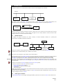
Communication between two devices via the modbus protocol takes place with an exchange of frames (structure).
In a frame, composed of a set of bits, there is a start, an end and an internal structure that can be exemplified by the
following outline:
Frames
Device
Function
8 bits Data Byte
Error Check
The maximum length of a packet is closely tied to the transmission/reception buffer of the interface used. It is therefore a
function of the resources. In any case, a message can be at most 256 bytes long.
4.2
The query-response cycle
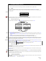
A communications cycle between a master and a slave device takes place by an exchange of frames:
QUERY Master
Device
Device
Function
Function
Eight bit – Data Bytes
Eight bit – Data Bytes
Error
Error
RESPONSE
Query
<IMG INFO>
28,3
29,3
1
Response
The query will contain the following fields:
Device address: address of the slave in the network. This address necessarily needs to be the same in both the query
•
and the response.
Function code: The function code in the query tells the slave device concerned (addressed) the type of action to
•
perform.
Data bytes: contain any additional information that the slave needs to perform the function.
•
Error check: The check error field provides a method to check the integrity of the message content
•
For example, the function with code 03 (decimal) requests the slave to read the registers (holding register) and to respond
with their values. The data field, in this example, will contain the data informing the slave from which register (variable) to
begin and for how many registers to continue reading
If the slave creates a normal response, the function code in the response is an echo of the query function code. The data
bytes field contains the data collected by the slave, such as the value of a register.
If an error occurs, the function code is modified to indicate that the response is an error-response and the data bytes field
contains a code describing the error.
The error check field enables the master to understand whether the message content is valid.
4.3
Serial transmission mode
The instruments can be configured to communicate with the Modbus network standard using two transmission codes:
ASCII and RTU.
They establish how the bits form the fields of the frame.
The type of coding used is pre-set by the firm or can be selected together with the communications parameters (parity,
baud rate, etc.).
The type of coding (ASCII/RTU), and relevant parameters (parity, baud rate) must be the same for all the devices
on the network.
The coding used by the Eliwell/Microtech devices is RTU; in the remainder of this manual we will therefore always either
explicitly or implicitly refer to this type of coding.
4.3.1
Character serial transmission
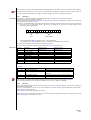
When messages are transmitted over a Modbus standard serial network, each character or byte is sent in this order (from
left to right):
Least Significant Bit (LSb) … … … Most Significant Bit (MSb).
MODBUS
6/20