1
To buy, sell, rent or trade-in this product please click on the link below:
http://www.avionteq.com/Druck-GE-Sensing-DPI-145-Aero-Precision-Multi-Function-Pressure-Indicator.aspx
GE
www.avionteq.com
Sensing & Inspection Technologies
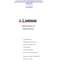
Druck DPI 145
Multi-Function Pressure Indicator
User Manual K0147
B DPI 145 PREC
Int
F.S.
ISION
20.000
00 ba
r
PRESS
URE IN
DICAT
OR
Barome
ter
bar
gauge
1 bar
bar
abs
MENU
g
© General Electric Company. All rights reserved.
i
DPI 145 User Manual
DPI 145
MULTI-FUNCTION
PRESSURE INDICATOR
DPI 145 Multi-Function Pressure Indicator
Software versions 3.XX
K0147 Issue No. 6
ii
K0147 Issue No. 6
DPI 145 User Manual
iii
Introduction
This technical manual provides operating instructions for the Druck DPI 145 Multifunction Pressure Indicator.
Safety
The manufacturer has designed this equipment to be safe when operated using the
procedures detailed in this manual. Do not use this equipment for any other purpose
than that stated.
This publication contains operating and safety instructions that must be followed to
ensure safe operation and to maintain the equipment in a safe condition. The safety
instructions are either warnings or cautions issued to protect the user and the
equipment from injury or damage.
Use suitably qualified* technicians and good engineering practice for all procedures in
this publication.
Toxic Materials
There are no known toxic materials used in this equipment.
Maintenance
The equipment must be maintained using the manufacturer’s procedures and should
be carried out by authorized service agents or the manufacturer’s service departments.
Technical Advice
For technical advice contact the manufacturer or subsidiary.
*
A qualified technician must have the necessary technical knowledge, documentation,
special test equipment and tools to carry out the required work on this equipment.
Pressure Safety
Do not allow pressures greater than the Safe Working Pressure to be applied to the
instrument refer to the Specification section of this manual.
K0147 Issue No. 6
iv
Symbols
This symbol, on the equipment, indicates that the user must refer to the user
manual. This symbol, in this manual, indicates a hazardous operation.
This equipment meets the requirements of all the relevant European safety
directives. The equipment carries the CE mark.
Do not dispose of this product as household waste. Use an approved
organisation that collects and/or recycles waste electrical and electronic
equipment. For more information, contact one of these:
our customer service department (contact us at www.gesensing.com)
your local government office
K0147 Issue No. 6
Contents
v
1
1.1
1.2
1.3
INTRODUCTION ....................................................................................................................................... 1-1
Instrument Specification .................................................................................................................... 1-2
Options ....................................................................................................................................................... 1-6
Associated Publications ...................................................................................................................... 1-7
2
2.1
2.2
2.2.1
2.2.2
2.2.3
FUNCTIONAL DESCRIPTION ............................................................................................................... 2-1
General ....................................................................................................................................................... 2-1
Familiarisation ........................................................................................................................................ 2-3
Indicator Mode ................................................................................................................................ 2-6
Barometer Mode ............................................................................................................................ 2-7
Option ................................................................................................................................................. 2-7
3
3.1
3.1.1
3.1.2
3.1.3
3.2
3.3
3.4
3.4.1
3.5
3.5.1
3.5.2
3.6
3.6.1
3.6.2
3.7
3.8
INSTALLATION ......................................................................................................................................... 3-1
Mounting ................................................................................................................................................... 3-1
Free Standing .................................................................................................................................. 3-1
Rack Mounting ................................................................................................................................ 3-4
Panel Mounting ............................................................................................................................... 3-6
Connector Connections ...................................................................................................................... 3-6
Pressure Connections .......................................................................................................................... 3-7
Electrical Connections ......................................................................................................................... 3-7
Power Supply Connections ....................................................................................................... 3-8
Communication Interface Connections ...................................................................................... 3-10
RS 232 Interface ............................................................................................................................. 3-10
IEEE 488 Interface .......................................................................................................................... 3-11
Connection of External Transducers ............................................................................................ 3-11
Piezo Resistive Types .................................................................................................................... 3-12
Resonant Transducer Types ..................................................................................................... 3-12
Switch Test and Analogue (I/V) Output ........................................................................................ 3-13
Installation of Software Options ..................................................................................................... 3-14
4
4.1
4.1.1
4.2
4.3
OPERATION ............................................................................................................................................... 4-1
General ....................................................................................................................................................... 4-1
Menu Icons ....................................................................................................................................... 4-1
Preparation for Operation ................................................................................................................. 4-2
Instrument Set-up ................................................................................................................................. 4-2
First Time Operation (Setup or Cal Pin) ........................................................................ 4-3
Instrument Clock Time and Date .................................................................................... 4-4
Display Parameters .............................................................................................................. 4-5
Set-up Units ...................................................................................................................................... 4-6
Set-up Data Communications ................................................................................................. 4-8
RS232 Set-up ........................................................................................................................... 4-8
IEEE 488 Set-up ....................................................................................................................... 4-9
Select Printer and Print Screen ................................................................................................ 4-10
4.3.1
4.3.2
4.3.3
Continued...
K0147 Issue No. 6
vi
DPI 145 User Manual
Contents Continued...
4.3.4
Channel Display Functions ........................................................................................................ 4-11
Resolution .................................................................................................................................. 4-11
Name ........................................................................................................................................... 4-12
Filter ............................................................................................................................................. 4-13
Protection .................................................................................................................................. 4-14
Alarms ......................................................................................................................................... 4-14
4.3.5
Set-up Barometer Parameters ................................................................................................ 4-18
Channel ...................................................................................................................................... 4-19
Height .......................................................................................................................................... 4-19
Temperature ............................................................................................................................ 4-20
4.4
Use Instrument as Barometer ......................................................................................................... 4-20
Display ........................................................................................................................................ 4-21
Units ............................................................................................................................................. 4-21
Process ....................................................................................................................................... 4-21
Barograph ................................................................................................................................. 4-22
4.5
Indicator Mode ........................................................................................................................................ 4-23
4.5.1
Select Channel for Display ......................................................................................................... 4-23
4.5.2
Change Channel Units ................................................................................................................ 4-24
4.5.3
Set-up a Channel Process ......................................................................................................... 4-25
4.5.4
Use of the Maths Function ........................................................................................................ 4-28
4.6
Measuring a Pressure .......................................................................................................................... 4-29
4.6.1
Connection of External Pressure Transducers ................................................................. 4-30
4.7
Leak Test .................................................................................................................................................... 4-33
4.8
I/V Output .................................................................................................................................................. 4-35
4.8.1
Generating of Output Voltages or Currents (Prog. Output) ........................................ 4-35
4.8.2
Set an Analogue Output Proportional to an Indicated Measurand ........................ 4-37
4.9
Pressure Switch Testing ..................................................................................................................... 4-38
4.10
Data (Screen) Store Operations ....................................................................................................... 4-40
4.10.1
Screen Store Operations ............................................................................................................ 4-40
4.10.2
Configuration Store Operations .............................................................................................. 4-41
4.11
Data Log .................................................................................................................................................... 4-43
4.11.1
Use of Data Log Directory and Delete Functions ............................................................ 4-44
4.11.2
Data Log Record Operations .................................................................................................... 4-45
4.11.3
Data Log Replay Operations .................................................................................................... 4-52
4.12
Data (store) Recall Operations ......................................................................................................... 4-56
4.12.1
Screen Recall Operations ........................................................................................................... 4-56
4.12.2
Configuration Recall Operations ............................................................................................ 4-57
4.13
Software Options - Aeronautical .................................................................................................... 4-58
4.13.1
Form of Test ..................................................................................................................................... 4-58
4.13.2
Operation .......................................................................................................................................... 4.59
4.13.3
Change Aeronautical Settings ................................................................................................. 4-61
4.13.4
Rate of Climb Tests ....................................................................................................................... 4-62
4.14
Software Options - Airfield Barometer ......................................................................................... 4-64
4.14.1
Airfield Option Set-up ................................................................................................................... 4-66
4.14.2
Change Airfield Setting ............................................................................................................... 4-68
Continued...
K0147 Issue No. 6
vii
Contents
Contents Continued
5
CALIBRATION ........................................................................................................................................... 5-1
5.1
Calibration Check .................................................................................................................................. 5-1
5.2
Calibration Adjustment ....................................................................................................................... 5-2
5.2.1
General Procedures ...................................................................................................................... 5-3
5.2.2
Cal Status Menu ............................................................................................................................. 5-4
5.3
Transducer Types .................................................................................................................................. 5-5
5.3.1.
Internal Piezo Resistive Types .................................................................................................. 5-5
5.3.2.
External Piezo Resistive Types ................................................................................................. 5-6
5.3.3
Internal Resonant Types ............................................................................................................. 5-6
5.3.4
External Resonant Types ............................................................................................................ 5-6
5.4
Using the Calibration Menu .............................................................................................................. 5-7
5.4.1.
Selection of new P.I.N. Number ............................................................................................... 5-8
5.4.2.
Instrument Pressure Calibration Menu Option ................................................................ 5-9
5.4.3.
Electrical Calibration Menu Options ...................................................................................... 5-12
5.4.4.
Ratio Calibration Option ............................................................................................................. 5-13
5.5
Correction of Zero and Full Scale Errors ..................................................................................... 5-14
5.5.1
Internal Transducers .................................................................................................................... 5-14
Fixed Range PRT and Digitally Compensated PRT's5-14
Auto Ranging Pair .................................................................................................................. 5-15
Resonant Transducers ........................................................................................................ 5-17
5.5.2
External Transducers ................................................................................................................... 5-18
Fixed Range PRT and Digitally Compensated PRT's5-18
Resonant Sensors .................................................................................................................. 5-20
5.5.3
External Transducer Identification Entry (PRT Types only) ......................................... 5-20
5.6
Linearity Compensation ..................................................................................................................... 5-21
5.6.1
Internal Transducers .................................................................................................................... 5-22
Fixed Range PRT and Digitally Compensated PRT's5-22
Auto Ranging Pair .................................................................................................................. 5-23
Resonant Transducers (Internal) ..................................................................................... 5-26
5.6.2
External Transducers ................................................................................................................... 5-29
Fixed Range PRT and Digitally Compensated PRT's5-29
Resonant Transducers (External) .................................................................................... 5-30
5.7
Temperature Effects Compensation ............................................................................................. 5-31
5.8
Analogue and Programmable Output Adjustment ................................................................ 5-32
6
6.1
6.2
6.3
6.4
6.5
MAINTENANCE ........................................................................................................................................ 6-1
Safety Instructions ................................................................................................................................ 6-1
Fuse Replacement ................................................................................................................................ 6-2
Cleaning ..................................................................................................................................................... 6-4
Memory and Clock Support Battery .............................................................................................. 6-4
Approved Service Agents ................................................................................................................... 6-5
K0147 Issue No. 6
DPI 145 User Manual
viii
ABBREVIATIONS
NOTE: Abbreviations are the same in the singular and plural.
ac
atm
°
C
°
F
COM
cm2
contd
dc
DMM
DUT
ENT
FS
ft
N/C
kg
Pa
LSD
PIN
M
mA
mm
No.
PRESS
PTX
RDG
RS232
SCPI
T
VAC
K0147 Issue No. 6
alternating current
atmosphere
degrees Celsius
degrees Fahrenheit
common
centimetre squared
continued
direct current
digital multimeter
device under test
enter
full-scale
feet
not connected
kilogram
Pascal
Least Significant Digit
personal identification number
metres
milli Amperes
milli metres
Piezo Resistive
pressure
pressure transmitter
reading
serial data transmission standard
Standard Commands for Programmable
Instruments
tare
vacuum
1: INTRODUCTION
1
1-1
INTRODUCTION
1
The DPI 145 is a high precision pressure instrument, designed to operate as a
general purpose indicator and barometer. The instrument is designed for general
laboratory use and is available in either free standing or rack mounting form.
In its role as an indicator, up to six measuring channels are provided. The customer
can choose from a range of pressure transducers mounted within the instrument or
connected externally.
The instrument can accommodate Druck piezo-resistive transducers offering
measurement over a wide pressure range and compatibility with a wide range of
fluids. In addition, Druck micro-machined resonant sensors can be employed for
high stability low pressure measurements. The Solartron 7881 resonant cylinder
transducer is also available for this purpose. Where the greatest precision over a
wide range of pressures is required an auto-ranging pair of piezo resistive
transducers can be fitted.
Using many advanced measurement features including extensive linearization and
thermal compensation of both the sensor and electronics, the highest stability and
precision of measurement is achieved.
The user can control the instrument via the high contrast display and keyboard or
from a computer via the RS232 and IEEE 488 interfaces. The instrumentation
standard communication language SCPI is used, reducing programming time and
assisting interchangeability of instruments.
Many powerful features are built into the instrument allowing the measured
pressure to be displayed in various ways. Filters and offsets can be applied in
addition to a wide range of measuring units. Mathematical functions can be
performed between channels, and simple conversion formulae can easily be
entered
Additionally, the instrument has specific modes of operation such as barometer,
airfield barometer and aeronautical instrument calibration. In these modes the
display format and facilities change in order to meet the specific requirements of
these applications. The instrument is also capable of generating electrical output
voltages and currents. These electrical outputs can be programmed to any level
within the range of the instrument or be linearly related to any measurement or
process channel output.
The unit can be powered either from an a.c. mains source or from a low voltage d.c.
source.
K0147 Issue No. 6
1-2
1.1
DPI 145 User Manual
Instrument Specification
Internal Measuring Channels
The instrument performance is determined by the sensor(s) fitted internally and
externally. See Option B for External Transducer performance.
Pressure Ranges
Fixed Range Piezo Resistive Sensors (PRT)
Sensors can be fitted giving full-scale values within the following limits.
Gauge:
70 mbar to 70 bar
Sealed Gauge:
71 to 350 bar
Absolute:
350 mbar to 350 bar
Differential:
175 mbar to 70 bar
Auto-Ranging Piezo Resistive Sensors
Discrete ranges, gauge only.
Gauge:
-1 to 20 bar
Resonant Sensors
All resonant sensors are absolute types and cover the following discrete ranges.
Druck Resonant Pressure Transducer (RPT)
Absolute:
35 to 1300 mbar
35 to 2620 mbar
35 to 3500 mbar
750 to 1150 mbar (barometric)
Solartron 7881
Absolute:
35 to 1300 mbar
35 to 2600 mbar
35 to 3500 mbar
800 to 1150 mbar (barometric)
Maximum Safe Working Pressure
1.5 x F.S. up to a maximum working pressure of 385 bar (at 350 bar 1.1 x F.S.). No
shift in calibration is caused by pressures to these values.
K0147 Issue No. 6
1: INTRODUCTION
1-3
Measuring Accuracy
Assuming regular zeroing, positive direction performance unless otherwise stated.
All values ±1 digit.
Piezo Resistive Sensors
Fixed Range PRT
Linearity, Hysteresis &
Repeatability
12 month stability
0 to 200 mbar
>20% F.S. ±0.05% rdg.
<20% F.S. ±0.01% F.S.
0.25% rdg.
201 mbar to 70 bar
>20% F.S. ±0.025% rdg.
<20% F.S. ±0.005% F.S.
0.12% rdg.
>20% F.S. ±0.04% rdg.
<20% F.S. ±0.008% F.S.
0.2% rdg.
Above 70 bar
Auto-Ranging PRT
Linearity, Hysteresis &
Repeatability
>1% F.S. ±0.025% rdg.
<1% F.S. ±0.00025% F.S.
To 20 bar full-scale
12 month stability
0.01% rdg.
Resonant Sensors
Linearity, Hysteresis &
Repeatability +
10-30 deg C Temp. Effects
12 month stability
Druck RPT
750 to 1150 mbar
±0.013% F.S.
±0.01% F.S.
Solartron 7881
all ranges
±0.02% rdg.
plus ±0.01% F.S.
plus ±0.005% F.S.
Sensor Type
Media Compatibility
Fixed Range Piezo Resistive:
Auto-Range Piezo Resistive:
Solartron 7881:
most fluids
most non-corrosive gases
clean dry air, refer to manufacturer
K0147 Issue No. 6
1
1-4
DPI 145 User Manual
Measurement Noise
Typical values:Fixed piezo resistive:
Auto-ranging PRT:
Resonant:
±5 ppm F.S.
±0.5 ppm F.S.
±5 ppm F.S.
Update Rate
Dependent on number of channels displayed, maximum two updates per second.
Temperature Effects
Piezo resistive:
Resonant:
10 to 30°C averaged coefficient = ±0.002% rdg./°C
Included in accuracy
Interfaces
Analogue Output
Proportional to selected reading. May be selected as voltage or current. User
selectable zero and full-scale.
Current range:
0 to 30 mA
Voltage range:
0 to +10 V
Accuracy:
±0.05% rdg. ±0.005% F.S. ±1 digit
Programmable Output
Range:
As analogue output
Accuracy
Current:
±0.035% rdg. plus ±0.01% F.S. ±1 digit
Voltage:
±0.025% rdg. plus ±0.01% F.S. ±1 digit
Accuracies include a 90 day stability and calibration uncertainties.
Digital Communications
RS232 serial data link using SCPI protocol.
Power Supply
A.C. :
D.C. :
Power consumption:
80 to 260 V at 45 to 410 Hz
9 to 32 V d.c.
10 watts max.
Electrical Safety
Meets BSEN61010-1 as applicable.
The instrument must be connected to the power supply protective earth when
operated from a mains supply. Safe for use up to 2,000 metres above sea level.
K0147 Issue No. 6
1: INTRODUCTION
1-5
Environmental Specification
1
EMC
This equipment meets the following EMC requirements:EN50081-1 (Emissions) and EN50082-1 (Immunity).
Temperature
Operating:
Storage:
0° to 50°C
-20° to 70°C
Sealing
Front Panel:
IP54
Enclosure:
IP41
The user must provide a suitable protection in more severe environments.
Humidity
To IEC 1010, 80% up to 30°C decreasing to 50% at 40°C.
Shock & Vibration
Designed to meet IEC 1010.
Weight
Dependent on transducer fit, typically:
4.6 kg
Dimensions
110 mm high, 290 mm wide, 250 mm deep
3U high when rack mounted
Accessories
The instrument is despatched with:
User Manual (K0147)
Calibration Certificates
Power supply cable
K0147 Issue No. 6
1-6
1.2
DPI 145 User Manual
Options
Option A - IEEE 488 (GPIB) Digital Communications Bus
Software to operate the IEEE 488 interface can be supplied at the time of purchase
or as a retrofitted option. The software is installed and enabled by the use of an
one-time electronic key.
The digital communications bus uses the SCPI protocol.
CAUTION:
NOTE:
FOR EMC COMPLIANCE, ALL IEEE CABLES MUST BE LESS THAN 3M
IN LENGTH.
The IEEE 488 connector is always fitted but the IEEE software
option must have been installed before the connector can be used.
Option B - External Transducers
Up to a maximum of ten external piezo resistor transducers and one external
resonant transducer can be used with the DPI 145. The external transducers are
specially made for this application and come complete with 2 metres of cable
terminated with a 12-way plug for direct connection to the instrument. Piezo
resistive transducers are available to cover gauge, absolute and differential
applications and resonant transducers for absolute applications.
The following options are available:
Option B1
Option B2
Option B3
Provides normal piezo-resistive transducer temperature error
bands.
Provides enhanced temperature coefficients as detailed for
internal sensors.
Any transducer with calibration accuracy as found.
For any further details, please refer to the manufacturer.
Option C - Negative Calibration
A channel fitted with a gauge or differential fixed range PR transducer can have an
additional calibration in the negative pressure direction.
K0147 Issue No. 6
1: INTRODUCTION
1-7
Option D - Aeronautical
This software option can be fitted at time of manufacturer or retrofitted by the user.
The software is installed and enabled by the use of a one-time electronic key (refer
to Section 3.6). The manufacturer can advise on the optimum transducer types for
use with this option.
The option is designed to enable the accurate calibration of altimeters, rate of climb
and airspeed indicators.
Option E - Airfield Barometer
This software option can be fitted at time of manufacture or retrofitted by the user.
The software is installed and enabled by the use of a one-time electronic key.
The option is designed to extend the standard meteorological barometer features
to those required for use as an airfield barometer. Features such as QNH and
multiple runways offsets are added to the existing QFE, QFF and Trend displays.
Option F - Rack Mount Kit
A plate allowing the instrument to be mounted directly into a 19 inch rack
occupying 3U of rack height.
Option G - Connectors
The following mating connectors can be supplied.
Manufacturer's
Order Code
Function
Description
Supplier
Part Number
DPI 145-G4
D.C. Power Input
3-way
Plug
Lemo
163-047
DPI 145-G1
External Trans.
12-way
Plug
Lemo
163-032*
163-033*
DPI 145-G2
RS232
9-way D-type
Plug
Various
154-003*
145-008*
DPI 145-G3
I/V Output &
Switch Input
BNC
Various
163-048
* Both items required
1.3
Associated Publications
The following publication is associated with this manual.
K179 - SCPI Commands for Druck Instruments
K0147 Issue No. 6
1
1-8
DPI 145 User Manual
intentionally left blank
K0147 Issue No. 6
2: Functional Description
2
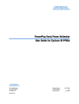
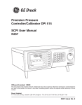
FUNCTIONAL DESCRIPTION (Fig. 2.1)
2.1
General
2-1
The DPI 145 is a six channel instrument (M1 to M6), designed to process the output
of up to three piezo-resistive pressure transducers and up to three resonant
pressure transducers.
The piezo-resistive channels, [M1] to [M3], may be configured in a number of ways.
Transducers connected to [M1] and [M2] are mounted within the instrument case
and be either gauge or differential type. Alternatively [M1], [M2] can be utilised for
processing the outputs of an auto-ranging pair. The -1 to 20 bar gauge autoranging sensor utilises two digitally characterised transducers, one covering the -1
to 2 bar range and the other, -2 to 20 bar range respectively.
[M3] is used for processing the output of an external PRT transducer. This
transducer, which maybe either a conventional piezo-resistive type or a digitally
characterised type, can cover any range up to 700 bar (10,500 psi). The resonant
sensor channels, are [M4], [M5] and [M6].
Channels [M4] and [M5] are allocated to internally mounted resonant transducers
and can be vibrating cylinder or resonant silicon sensors. Channel [M6] is allocated
for an externally mounted resonant transducer.
A BNC socket is provided for analogue output. This socket can be programmed to
source current or voltage. These electrical outputs can also be set to be
proportional to any measurand (e.g.) either pressure or the resultant of any
processed channel. It may also be programmed to a particular voltage or current.
The instrument also provides a BNC socket to enable the instrument to accept
trigger inputs for its internal data logger and pressure switch functions.
An RS232 or optional IEEE 488 interface provides a communication channel
between the instrument and a printer or computer system.
An internal power supply unit provides all the regulated supplies that are needed to
power the instrument and to source the electrical output signals. The instrument
has the facility to be either a.c. mains powered or powered from an external d.c.
source.
K0147 Issue No. 6
2
2-2
DPI 145 User Manual
The instrument's display can be configured to show the output of a single
measuring channel or any number of channels simultaneously, together with the
clock time (up to a maximum number of eight channels). If a group of channels are
being displayed simultaneously, the character size is automatically adjusted and
the display partitioned to accommodate the read-out associated with each
channel.
KEYBOARD
AUTO RANGING PAIR
PROCESS CHANNELS
BACK-LIT
LCD
(Chan. 1 & 2 option)
LP (2 BAR)
INLET
P1
P2
P3
P4
P5
P6
[M1]
P
V
MANIFOLD
HP (2O BAR)
[M2]
P
RS 232
INTERFACE
RS232
INPUT/OUTPUT
V
EXT
PRT
[M3]
P
P1
MICROCONTROLLER
SYSTEM
V
RPT
[M4]
P
INLET
F
ANA/PROG
O/P
PROGRAMMABLE/
ANALOGUE OUTPUTS
& SWITCH TEST
SW TEST
INPUT
RPT
[M5]
P
INLET
F
EXTERNAL
RPT
[M6]
P
IEEE 488
(option)
F
POWER
SUPPLY
A.C. POWER
DC POWER
IN/OUT
SYSTEM POWER
SUPPLIES &
DISPLAY H.T.
DPI 145
Figure 2.1 - DPI 145 Function Diagram - Typical Configuration
K0147 Issue No. 6
2: Functional Description
2.2
2-3
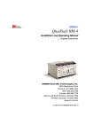
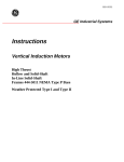
Familiarisation
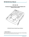
The instrument power switch is located adjacent to the power inlet on the rear
panel. All other controls are located on the front panel as shown in Figure 2.2. The
instrument stores its configuration at switch-off and returns to this condition when
power is restored. All data stored in the instrument memory is also retained when
power is removed.
B DPI 145 PREC
Int
F.S.
ISION
20.000
00 ba
r
PRESS
URE IN
DICAT
OR
Barom
eter
bar
gauge
1 bar
bar
abs
MENU
Figure 2.2 - DPI 145 Front Panel
Measured values and key functions/user dialogue are shown on a back-lit graphics
Liquid Crystal Display. The user alters the function of the instrument using the
control keys, four of which are function keys (labelled F1 to F4) whose purpose at
any time is indicated on the display above these keys.
K0147 Issue No. 6
2
2-4
DPI 145 User Manual
A range of transducers is available for the instrument covering piezo resistive silicon
diaphragm, resonant silicon diaphragm and resonant cylinder types. Some of these
are available as a digitally characterised auto-ranging module, others are available
in internal and external mounting. Whatever the fit of transducers, the instrument
has six Measuring Channels (M1 to M6) to which three transducers (RPT) and three
are for piezo resistive transducers (PRT). One of each of these types is reserved for
external transducers i.e. the instrument has one external PRT channel and one
external RPT channel.
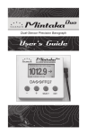
In addition to the measuring channels, the instrument can display up to six Process
Channels (P1 to P6). A process channel is a pseudo channel that does not carry
raw measured data, instead it carries either processed or mathematically derived
data. Figure 2.3 shows the concept.
MEASUREMENT CHANNELS
MC3
M3
MC1
M1
MC3
M6
MC1
M2
MC2
MC1
M4
MC1
M5
EXTERNAL
INTERNAL
PROGRAMMABLE PROCESS CHANNELS
P1
P2
P3
P4
P5
P6
M1 to M3 are PRT Channels
M4 to M6 are RPT Channels
DISPLAY
M1
M2
P3
MC4
M3
P3 = (M1 + M3)*
P2 = (M1 - TARE)*
M4
P2
P1 = (M1 MAX)*
P1
* TYPICAL ONLY
T:
16:35
CONFIGURED DISPLAY (TYPICAL)
Figure 2.3 - Measurement and Process Channel Display
K0147 Issue No. 6
2: Functional Description
2-5
For example measuring channel [1] (M1) may be configured in an instrument as a 2
bar g channel but process channel [2] (P2) may carry a version of M1 which has had
atmospheric pressure added to it thus giving an absolute pressure reading.
Alternatively P2 could be programmed to carry a tared reading or the peak of M1.
The processes available are Min, Max, Tare, %FS (percentage full-scale) and Flow.
The process channel concept is used again in the mathematical functions of the
instrument. If, for example, the instrument was programmed to subtract M1 from
M2, say for a differential measurement, then the result will be placed in a process
channel.
Once a process channel has been loaded with data in this way it can be controlled,
for display and process purposes, in the same manner as a measuring channel.
Any combination of process or measurement channels, up to a maximum of eight
at any one time, may be displayed.
Four modes of operation are supplied as standard, further modes can be purchased
as options. Indicator mode is a flexible general purpose pressure
measurement mode, while Barometer mode is aimed specifically at the
requirements of atmospheric pressure measurement for meteorological
applications. Switch Test, enabled by pressing the SW key, allows easy and
comprehensive testing of pressure switches. Leak Test, entered by pressing the
Leak key, allows pressure drop and leak rate to be measured over a programmable
time interval.
K0147 Issue No. 6
2
2-6
2.2.1
DPI 145 User Manual
Indicator Mode
This mode provides access to all the pressure transducers and all the processing
and mathematical functions. With Indicator mode enabled, a total of eight values
can be displayed. All six measuring channels and all six process channels can be
individually accessible. The features of the Indicator mode are:
Display
Allows one or several of the measuring and process channels to be called
onto the display. The instrument automatically adjusts the display window
and character sizes as more data is called onto the screen.
Units
Allows the selection of one of four regular units to be applied to any channel.
The regular units can be chosen from an extensive list displayed under the
Setup menu.
Process
Allows the measured value to be modified by offsets such as Tare, to be
expressed as a Maximum or Minimum value, or as a percentage of a
nominated full scale. A programmable filter gives steady readings when
required, without losing fast response to transients.
Maths
This feature enables the user to enter simple mathematical relationships
between any of the channels and display the result. Constants can also be
entered.
K0147 Issue No. 6
2: Functional Description
2.2.2
2-7
Barometer Mode
This operational mode focuses the instrument onto the chosen barometric
transducer. The barometric transducer can be nominated under the Setup menu
from any of the six Measuring Channels. Data from the barometric transducer is
shown as Local Pressure (QFE) and equivalent Sea Level Pressure (QFF).
Three hour Pressure Trend can also be displayed.
2.2.3
Option
Additional Option modes will also focus on specific applications such as the airfield
barometer mode, and the aeronautical instrument calibration mode.
K0147 Issue No. 6
2
2-8
DPI 145 User Manual
intentionally left blank
K0147 Issue No. 6
3: Installation
3
3-1
INSTALLATION
Safety Instruction
THE INSTALLATION OF ELECTRICAL AND PNEUMATIC SUPPLIES
MUST BE CARRIED OUT BY AN INSTALLATION TECHNICIAN*.
*An installation technician must have the necessary technical knowledge,
documentation, special test equipment and tools to carry out the work on this
equipment.
3.1
Mounting
3
There are three ways to mount the instrument:
Free standing, with or without carrying the handle.
In a 3U high, standard 19" rack.
Panel mounted.
The instrument, which is supplied with its carrying handle fitted, has no significant
orientation sensitivity.
3.1.1
Free Standing
For the standing applications with the handle fitted, the handle position can be
moved by pressing the buttons located at each end of the handle and rotating the
handle to the required position.
K0147 Issue No. 6
DPI 145 User Manual
3-2
Removal of Carrying Handle
For free standing applications not requiring the carrying handle to be fitted,
or in preparation for either rack or panel mounting, the carrying handle can
be removed as follows, refer to Fig. 3.1.
3
1
2
2
3
Removal
4
Replacement
Figure 3.1 - Carrying Handle Removal
Removal
Turn the instrument around to gain access to the rear panel.
Switch off the power supply to the instrument and disconnect the IEC
moulded connector from the power socket.
Insert a screwdriver (1) into one of the recesses in the rear panel as shown in
Fig. 3.1, release the spring clip (2) retaining the side plate and slide the side
plate (3) out approximately 10 mm.
K0147 Issue No. 6
3: Installation
3-3
Release the corresponding side plate on the other side of the instrument in
a similar manner and then slide both side plates out together, complete
with carrying handle (4).
Ensure that the side plates (3) and handle/adaptor block assembly are
stored in a safe place. It is recommended that for safe storage, the side
plates be re-inserted in the side channels of the instrument.
Reconnect the moulded mains power connector to the power socket and
switch the power supply on. The instrument is now ready for connection
and operation. Connection details are given in Section 3.2 to 3.7.
Replacement
Switch off the power supply to the instrument and disconnect the IEC
moulded connector from the power socket.
If the side plates (3) are stored in the side channels, release retaining spring
with a screwdriver and slide out of the instrument.
Slot the side plates (3) into the adaptor blocks (5) (see also Fig. 3.2), fit the
handle across the instrument and slide in side plates until they lock.
Reconnect the moulded IEC connector and switch on the power supply. The
instrument is now ready for connection and operation. Connection details
are given in Section 3.2 to 3.7.
3
5
2
6
4
Figure 3.2 - Handle Assembly
K0147 Issue No. 6
3
DPI 145 User Manual
3-4
3.1.2
Rack Mounting (Figure 3.3)
To convert the DPI 145 instrument for rack mounting, a rack mounting kit is
required. This comprises a 3U high, 19" standard rack mounting facia panel with a
suitable cut-out for the instrument and two M6 cap screws.
To install the instrument into standard rack form, proceed as follows.
If the instrument has been previously installed, first isolate
and disconnect all power supplies.
Isolate all pressure supply lines and disconnect all pressure
inlets/outlets to the instrument.
Disconnect any electrical connectors which may be fitted to the instrument
(e.g.) external transducers, RS232 or IEEE 488 connectors or switch test and
I/V output leads.
If fitted, remove the carrying handle as described in Section 3.1.1.
Remove the carrying handle from the adaptor blocks (5) by unscrewing the
two countersunk socket-head screws (6) as shown in Fig. 3.2.
Remove the four screws (10) securing the lower cover of the instrument (9)
and remove the cover. Refer to Fig. 3.3.
Slide the instrument (rear first) through the rack front panel (7) as shown in
Fig. 3.3.
Fit a M6 cap screw (6) into each adaptor block (5) and partially screw into the
block.
NOTE: No screw thread should initially protrude through the block and the
stepped end of the block should be to the front.
K0147 Issue No. 6
3: Installation
3-5
Place an adaptor block into the recessed end of a side plate, with the
stepped end of the block facing towards the rack panel. Slide the side plate/
adaptor block (3/5) along one of the side channels of the instrument until it
locks into position.
Fit the other side plate/adaptor block (3/5) into the other side channel and
lock into position.
Tighten the M6 cap screw (8) on each side, evenly against the back of the
rack panel but do not over-tighten.
Refit the bottom panel (9) to the instrument.
Fit the assembly into the cubicle rack and connect the pressure and
electrical connectors as described in Sections 3.2. to 3.7.
3
7
5
3
10
9
8
Figure 3.3 - Rack Mounting Arrangement
K0147 Issue No. 6
DPI 145 User Manual
3-6
3.1.3
Panel Mounting (Figure 3.4)
The method of mounting the instrument into a panel is similar to the method for
mounting the instrument into a rack, the instrument being mounted through the
panel cut-out rather than to the rack facia panel.
The panel cut-out size is 284 mm x 106 mm.
3.2
Connector Connections
All connections to the instrument are made to the rear panel. Fig 3.4 shows a
diagram of a typical rear panel layout, together with the electrical pressure
connections.
Figure 3.4 - DPI 145 Rear Panel
K0147 Issue No. 6
3: Installation
3.3
3-7
Pressure Connections
Pressure Safety Instructions
TURN OFF THE SOURCE PRESSURE AND VENT THE PRESSURE
BEFORE DISCONNECTING OR CONNECTING THE PRESSURE LINES.
PROCEED WITH CARE.
ONLY USE EQUIPMENT WITH THE CORRECT PRESSURE RATING.
Connection
To connect up to a measuring port, proceed as follows.
Ensure that the pressure supply is isolated from the supply line. It is
recommended that an isolation valve be fitted between the pressure
source and the instrument.
Fit the pressure supply line to the correct measuring port, fitting a
bonded seal between the pressure union and the measuring port. All
measuring ports use a G1/8 thread. Ensure that the coupling is tight and
check for leaks. Use the Leak Test facility if required (refer to Section 4.7).
NOTE:
3.4
The Barometric pressure sensors have a limited operating and
calibration range (refer to Section 1, Specification).
Electrical Connections
Electrical Safety Instructions
USE THE CORRECT SUPPLY SETTINGS. OPERATING VOLTAGE
RANGES ARE MARKED ON THE REAR PANEL OF THE INSTRUMENT
AND ARE GIVEN IN SECTION 1, SPECIFICATION.
WHEN THE INSTRUMENT IS POWERED FROM LOW VOLTAGE D.C.,
ENSURE THAT THE CORRECT VOLTAGE AND POLARITY ARE
APPLIED TO THE INSTRUMENT.
THE EARTH LEAD (COLOURED GREEN/YELLOW) MUST BE
CONNECTED TO THE MAINS SAFETY EARTH.
K0147 Issue No. 6
3
DPI 145 User Manual
3-8
BEFORE MAKING ANY ELECTRICAL CONNECTIONS TO THE REAR
PANEL, SWITCH THE INSTRUMENT OFF.
BEFORE REMOVING ANY COVERS, ISOLATE THE INSTRUMENT
FROM ALL ITS SUPPLIES.
3.4.1
Power Supply Connections
The instrument can be powered either from a.c. mains or from a d.c. supply.
Section 1, specification, gives full details of the a.c. and d.c. power supply
requirements.
A.C. Power Supply
The a.c. power supply inlet assembly is located on the rear panel as shown
on Fig. 3.5. A fuse and power on/off switch are also contained within the
assembly, details of the fuse fitting being shown in Fig. 3.5.
1
2
3
4
Figure 3.5 - A.C. Power Supply Socket
To connect the a.c. power supply, proceed as follows.
Connect the moulded IEC connector (1) into the power supply socket (4) and
connect to a suitable a.c. power source.
Switch on the a.c. power supply and switch the instrument ON.
K0147 Issue No. 6
3: Installation
3-9
If the instrument display does not light up, isolate the
external power supply and disconnect the IEC connector (1)
from the power socket (4).
Remove the fuse holder (2) as shown in Fig 3.5. and insert a
new fuse.
NOTE:
A spare fuse (3) is contained within the fuse holder (2).
Section 6 for details of fuse.
Refer to
Reconnect the IEC connector (1) and switch on the power supply and the
instrument.
Should the moulded-on mains connector need to be removed from the
cable assembly (1) for any reason the cable connections are.
Blue
Brown
Green/Yellow
-
Neutral
Live
Protective Earth
D.C. Power Supply
The d.c. input connector is located on the rear panel in the position shown on
Fig. 3.5. To connect the input, proceed as follows.
1
1.
2.
3.
2
Supply (+ve)
Supply (-ve)
Make no connection
3
Figure 3.6 - D.C. Power Supply Connector Pin Out
K0147 Issue No. 6
3
DPI 145 User Manual
3-10
Insert the d.c. power supply connector and switch on the supply.
NOTE:
The d.c. supply can be connected while the a.c. mains supply is
connected without risk of damage. However, if the instrument is to be
operate from the a.c. supply only, then the dc supply should be isolated.
To operate the instrument from the d.c. supply only, connect the d.c.
supply and disconnect, or switch off, the a.c. mains supply. The rear
panel on/off switch only controls the a.c. mains input.
3.5
Communication Interface Connections
Both the RS232 and IEEE 488 interfaces are connected using polarised plugs. To
connect up the interfaces, push the appropriate connectors into the relevant
sockets and tighten up the securing screws.
The RS232 is fitted as standard while IEEE 488 is a software option. The
communication protocol used on the IEEE 488 and RS232 interfaces is given
in Druck Publication No. K179.
3.5.1
RS232 Interface
The pin connections for the 9-pin RS232 connector and the relationship between
the instrument and the RS232 control signals, together with device
interconnection interface is shown in Table 1. The instrument is configured as Data
Circuit Terminating Equipment (DCE).
Instrument
Instrument
Function
Connector
Control Line
Signal
Direction
RS232
Terminology
9-way
D-type
Pin no.
Computer/Printer
Connector D-type
9-way
Pin no.
25-way
Pin no.
3
¬
TxD
3
2
TxD(O/P)
2
®
RxD
2
3
GND
5
«
GND
5
7
RxD(I/P)
CTS(I/P)
7
¬
RTS
7
4
RTS(O/P)
8
®
CTS
8
5
Pulled high
internally
1
®
RLSD
(DCD)
1
8
not used
4
¬
DTR
4
20
Pulled high
internally
6
®
DCR
DCE ready
6
6
«
Cable
screen
-
1
Equipment Connector
shell
chassis
Table 1 - RS232 Connections
K0147 Issue No. 6
3: Installation
3.5.2
3-11
IEEE 488 Interface
It should be noted that while the IEEE 488 connector is always fitted, the operating
software is a software option. Ensure that the IEEE 488 software option has been
installed before attempting to use the connector (refer to Section 3.8).
Pin No.
Signal
Pin No.
Signal
1
2
3
4
5
6
7
8
9
10
11
12
DI01
DI02
DI02
DI04
DI05
DAV
NRFD
NDAC
IFC
SRQ
ATN
Shield
13
14
15
16
17
18
19
20
21
22
23
24
DI05
DI06
DI07
DI08
REN
GND
GND
GND
GND
GND
GND
SIG GND
3
Table 2 - IEEE 488 Connections
Details of the communication protocol used on the IEEE 488 interface are given in
Druck Publication No. K179.
3.6
Connection of External Transducers
External transducers ordered as instrument options are delivered terminated with a
suitable connector for direct interfacing with the instrument.
Two types of external transducer may be used with the DPI 145, piezo resistive
types (digitally and non-digitally characterised) and resonant types. Both types use
the same type of connector but have differing pin allocations.
K0147 Issue No. 6
DPI 145 User Manual
3-12
3.6.1
Piezo Resistive Types
Connections for piezo resistive transducer types are shown in Fig. 3.7. The bridge
supply from the instrument is 5 V and the maximum current that can be drawn
from the instrument is 25 mA. When energised from 5 V, the bridge should have a
full scale output in the range 15 to 100 mV.
EXT PDCR
Conventional Bridge
Transducer Connections
5
6
7
8
Rear View
12
8
11
6
Bridge
Bridge
Bridge
Bridge
supply (-ve)
output (+ve)
output (-ve)
supply (+ve)
Additional Digitally
Characterised Connections
1
+5VD
2
EEPROM clock
3
EEPROM data
4
A0
9
A1
10
0VD
11
Temp sense diode (-ve)
12
Temp sense diode (+ve)
5
7
Figure 3.7 - External Transducer Connections (Piezo Resistive Types)
3.6.2
Resonant Transducer Types
Connections for resonant transducer types are shown in Fig. 3.8. It should be noted
that these connections are designed to interface with Druck RPT 200 style
transducers made for this instrument.
EXT RPT
Rear View
1
2
3
4
5
6
7
8
9
10
11
12
A0
Frequency signal
0V (supply)
+5V (A1)
-12V
Diode (+ve) sense
No connection
+12V
No connection
0V
EEPROM (clock)
EEPROM (data)
Figure 3.8 - External Transducer Connections (Resonant Types)
K0147 Issue No. 6
3: Installation
3-13
To connect an external transducer, plug the connector into the appropriate socket.
Resonant sensors should be plugged into the socket labelled EXT RPT and piezo
resistive sensors into the socket labelled EXT PDCR.
NOTE:
The external transducer input sockets, although of the same pattern,
are electrically different i.e. a Piezo Resistive device will not operate if
plugged into the Resonant Sensor socket and similarly, vice versa.
Secure the connector into the socket by tightening the connector securing screws.
For information on the use of external transducers with the equipment, refer to
Section 4.6.1. Section 5, Calibration, gives details of the calibration procedures for
external transducers. When a conventional PRT (not digitally characterised) is
connected to the instrument for the first time, the pressure reading will be shown
on the display in units of voltage not pressure. This is because the zero and full
scale offsets of the transducer must be corrected by compensation before voltage
can be interpolated as pressure. Refer to Section 5 for compensation details.
3.7
Switch Test and Analogue (I/V) Output
Connections to the Switch Test and the I/V Output sockets are made via coaxial
BNC connectors. To connect to either of these sockets, plug a lead fitted with a
BNC connector into the socket.
The pin-out of both sockets is shown in Fig. 3.9.
I/V Output
Shell
Centre
Switch
(-ve)
(+ve)
Shell
Centre
+5V
Voltage
or
Current
Source
+
GND
200
+ve
+
EXT
Load
Current or Voltage Output
Switch -ve
Switch +ve
External
Switch
GND
-ve
Switch Test Input
Figure 3.9 - Switch Test and I/V Output Socket Connections
K0147 Issue No. 6
3
DPI 145 User Manual
3-14
3.8
Installation of Software Options
If the software options of the instrument (IEEE 488, aeronautical and airfield) are
ordered with the instrument, they are enabled during manufacture. The following
procedure details the method of enabling the options after delivery of the
instrument.
The method of enabling the software options is by means of a software key. This
software key is supplied at the time of instrument options purchase and can be
used only once. To enable software options, proceed as follows.
Ensure that the instrument is switched off.
Insert a valid software key for the option(s) to be installed into the EXT PRT
socket, located on the rear panel of the instrument.
Switch on the instrument.
Depending upon the options purchased, the display will read as follows. The
example shows a key giving access to three options (e.g.),
Option Key:
Options:
Times Used:
Install Option ?
Yes
DPI 145
IEEE
0
One Time - Valid
AERO
AIRFIELD
No
In this example the display shows that the key in use is for a DPI 145, can be
used once only, has not been used to date (valid) and will enable the
installation of three software options.
K0147 Issue No. 6
3: Installation
3-15
To enable the options listed for use, press the Yes (F1) key. The display will
now change to indicate that the key has been used and is no longer valid
(e.g.),
Option Key:
DPI 145
One Time - Expired
Options:
IEEE
AERO
AIRFIELD
Times Used:
1
Installed on S/N 16061
Option Key is no longer valid
Quit
Note that the serial number of the instrument and the time of installation is
written to the key which, following installation, cannot be reused.
Press Quit (F1) and remove the software key from the EXT PRT socket. The
options are now enabled and available for use.
K0147 Issue No. 6
3
DPI 145 User Manual
3-16
intentionally left blank
K0147 Issue No. 6
4: Operation
4
4-1
OPERATION
4.1
General
This section, describes the use of the DPI 145 instrument, has been structured on a
functional basis.
The instrument can be fitted with up to six measurement channels and operates in
one of two basic modes, indicator or barometer. When configured as an indicator,
it can be set as a pressure switch tester and as a leak tester.
When configured as a barometer, the instrument indicates QFE (local
barometric pressure), QFF (barometric pressure at sea level), 3 hour Trend and
as a Barograph.
The Store and Datalog features of the instrument are applicable to both the
indicator and barometric modes of operation.
In addition to the pressure indicator and barometric pressure monitoring facilities,
the instrument can generate electrical output voltages and currents. These
electrical outputs can be programmed to any level within the range of the
instrument or be linearly related to any measurand or process channel. The
electrical output facilities are available in both the indicator and barometric modes
4.1.1
Menu Icons
In the following sections, the menu driven operations of the instrument are
supported by icons to show the structures associated with each command. A
typical icon is shown below, together with a description.
SET-UP
F1
F2
F3
F4
Units
Channel
Option
Barometer >>
F1
F2
F3
F4
Output
F1
F2
F3
F4
Cal. Status
F1
F2
F3
Comms
Printer
External
Cal
Test
Cal Pin
Set-up Pin
Sub-menu level - if option selected, shown in blue
menu
>>
Indicates presence of more functions on this level. Press
Menu Scroll to obtain next page of menu sub-options
Second page of sub-menu options
menu
Indicates presence of more functions on this level. Press Menu Scroll to
obtain next page of menu sub-options
Final sub-menu page (shown selected)
Cal Test
Display
Calendar
First menu level (system function)
>>
Press Menu Scroll to return to first page of options
Options shown indicate all the options available under the option
selected in block shown in blue above. This sub-sub option will also be
shown in blue
K0147 Issue No. 6
4
4-2
DPI 145 User Manual
The icon is divided into a number of blocks of four functions, each corresponding to
a function key as indicated. By working down the icon from top to bottom, the key
sequence for the system function at the lowest level is obtained. In this example,
the key sequence required in order to change the instrument's PIN number i.e. SETUP/Menu Scroll/Cal/Test (F2)/Cal Pin (F3).
4.2
Preparation for Operation
Normally, the DPI 145 instrument is a.c. mains powered. Additionally, it can be
powered from an external d.c. source (supply input ranges are detailed in
Section 1). When the instrument is being powered from an a.c. source, the
instrument provides an auxiliary d.c. output.
Switching ON and OFF
The instrument is switched ON using an ON/OFF switch located on the rear
panel of the instrument. The ON/OFF switch is an integral part of the a.c.
power connector and the mains supply fuse is also housed within the
connector.
After switch-on, a short initiation period follows during which, the electronic
control system is reset and the electrical outputs are switched off. When the
instrument display is ON, the instrument is ready for operation. If no
measurement or process channels are selected for display, clock time will be
displayed, together with a status message.
There are no channels selected.
4.3
Instrument Set-up
The instrument is supplied calibrated. A number of other parameters are also
factory set as follows:
Time
Date
Display timeout
Display resolution
Initial PIN code
K0147 Issue No. 6
-Set to U.K. local time
-Set to current date
-Disabled (off)
-Set to maximum (all channels)
-Set as 123
4: Operation
4-3
First Time Operation (setting Set-up or Cal PIN)
Access to the set-up and calibration utilities are password protected and a
factory set password (123) is entered into every instrument delivered. Since
misuse of the Set-up and/or the Cal/Test facility of an instrument can result
in the loss of its calibration, it is recommended that a separate PIN code is
set-up for each in order to restrict unauthorised access. To set a new PIN
code, proceed as follows:
Switch the instrument ON.
SET-UP
Units
Channel
Option
Barometer
Output
Comms
Printer
External
Cal. Status
!!
!!
Press the SET-UP key. Enter the set-up PIN code (123)
on the numeric key-pad and press ENTER.
Press MENU SCROLL (twice).
Select Cal/Test (F2) from the third page of Set-up
menu. The instrument will now prompt for entry of
the current password as follows:
Cal. Test
Display
Calendar
Cal
Test
Cal Pin
Set-up Pin
Cal/Test - Enter Pin Number:
#
Enter PIN number (123) on the numeric key-pad and
press ENTER. The instrument now displays the Cal/
Test menu.
4
Cal/Test Menu
Cal Test
Cal Pin
Set-up Pin
Select Set-up Pin (F4) or Cal Pin (F3) as required and a prompt is given
for a new PIN code.
Enter Pin Number: #
Enter key alone sets no Pin number
Enter a new PIN code via the numeric key-pad and press ENTER.
At the Verify new Pin code prompt, enter the new PIN code via the
numeric key-pad and press ENTER. If the new PIN code is entered
correctly, the instrument responds with Verification OK and exits the Setup mode. If the new PIN number is entered incorrectly at the Verify New
Pin code prompt, the instrument responds with Pin numbers do not
agree and exits the set-up mode, the old PIN code being retained.
Special Note
The instrument calibration can be lost by
incorrect use of the calibrate facility.
K0147 Issue No. 6
4-4
DPI 145 User Manual
Instrument Clock Time and Date
To set-up the instrument Clock Time and Date, proceed as follows.
Switch the instrument ON.
SET-UP
Units
Channel
Option
Barometer
Output
Comms
Printer
External
!!
Press the SET-UP key. If set, enter the Set-up PIN and
press ENTER.
Press MENU SCROLL twice to display the third page of
!!
Cal. Status
Cal. Test
Display
Calendar
Time
Date
On
Off
the Set-up menu.
Select Calendar (F4) from the third page of the Set-up
menu.
Select Time option (F1) and a prompt is given for a
new time.
Enter new Time (Hours. Mins):
#
Enter the new time in hours and minutes format via the numeric keypad, using the decimal point as a delimiter.
Press ENTER to accept the entered value.
To select Time to be displayed, press the On (F3) key. Conversely, to
remove time from the display, press the Off (F4) key.
NOTE:
If no channels are selected for display, time will be
displayed by default, whether or not it has been switched
on under this utility.
Select the Date (F2) option.
Enter New Date (Day.Mth.Year):
Enter the new date in Day, Month and Year format via the numeric
key-pad, using the decimal point as a delimiter.
Press ENTER to accept the entered date.
K0147 Issue No. 6
4: Operation
4-5
Display Parameters
When the instrument is first supplied, the display contrast and brightness are
both preset. To change the setting for either parameters, proceed as
follows.
Switch the instrument ON
SET-UP
Units
Channel
Option
Barometer
Output
Comms
Printer
External
Cal. Status
Cal. Test
Display
Calendar
Contrast
Brightness
Timeout
!!
!!
Press the SET-UP key followed by the MENU SCROLL
key twice (to obtain the third page of the set-up
menu). Pin code will need to be entered first (if set).
Select Display (F3) from the Set-up menu.
Select Contrast from the Display Set-up menu.
Use the Up (F1) and Down (F2) keys to change the
(e.g.) Contrast level to the required level.
Press Exit Menu once to return to the display Set-up
menu.
Select Timeout (F3) if required and enter required timeout period
(1 to 500 min) on the numeric key-pad followed by ENTER.
Press On (F1) to enable or Off (F2) to disable the timeout feature. At
the end of the timeout period, the display backlight is turned off.
Pressing any key immediately restores the display and resets the
timeout period.
Press Exit Menu three times to exit Set-up or allow sufficient time
for it to timeout.
K0147 Issue No. 6
4
4-6
4.3.1
DPI 145 User Manual
Set-up Units
Pressure
Instruments are supplied with their pressure scales programmed to specific
function keys as follows, bar (F1), psi (F2), mH20 (F3) and kPa (F4). U.S.
version of the instrument default to psi (F1), inHg (F2), inH2O (F3) and kPa
(F4). Japanese version default to kg/cm2 (F1), mmHg (F2), mH2O (F3) and
mbar (F4). To change any default setting, proceed as follows.
Switch the instrument ON
SET-UP
Units
Channel
Option
Barometer
Pressure
Spec'l
Press the SET-UP key. If set, enter the set-up PIN and
>>
press ENTER.
Select Units (F1) from the Set-up menu.
Select Pressure (F1) from the defaults units selection menu.
Operation of this key displays the full range of units available together with
an indication of the units to which each function key is currently assigned.
Use function keys to select units:
bar
Pa - F4
hPa
kPa
MPa
mbar - F1
kg/cm2
kg/m2
mmHg - F3
cmHg
mHg
mmH2O
cmH2O
mH2O
torr
atm
psi - F2
lb/ft2
inHg
inH2O
inH2O4
ftH2O
ftH2O4
"H2O60
Spec'l
Blank
Blank
Blank
The default setting for any key is changed by pressing the required function
key. This causes it to scroll through the menu, missing out units assigned to
the other function keys. The display shows the function key next to the
assigned pressure unit. Assigning three function keys to Blank provides the
facility of setting-up the instrument for single pressure unit operation.
K0147 Issue No. 6
4: Operation
4-7
Spec'l
The instrument has the facility to enable the operator to set-up a user
defined conversion factor for the pressure reading, the value being the
number of Pascals in one user defined unit. The default setting of the Pascals
to Spec'l conversion is 100 (scaling the pressure display in hPa).
By entering a conversion factor (Pascals to Spec'l unit factor) under set-up,
the instrument can be made to read any required unit. To change the
default setting of the special factor, proceed as follows.
Switch the instrument ON
SET-UP
Units
Channel
Option
Barometer >>
Pressure
Spec'l
Press the SET-UP key.
Select Units (F1) from the set-up menu.
Select Spec'l (F2) from the default units selection
menu. The instrument now displays a prompt
showing the current conversion factor and requesting
entry of a new factor.
Pascals to Spec'l Factor: # 100.00
Enter the required conversion factor on the numeric key-pad and
press ENTER.
Press EXIT MENU three times to exit set-up.
Assign a function key to Spec'l (refer to Pressure Section 4.3.1).
NOTE:
If the Spec'l conversion factor is changed while the Spec'l
units factor is selected, the Spec'l units factor will have to be
re-selected in order to make use of the new conversion factor.
K0147 Issue No. 6
4
4-8
4.3.2
DPI 145 User Manual
Set-up Data Communications
Comms
To set-up the instrument's data communications parameters, proceed as
follows.
Switch the instrument ON
SET-UP
Units
Channel
Option
Barometer
Output
Comms
Printer
External
Press the SET-UP key.
>>
Press Menu Scroll to select second page of set-up options.
Select Comms (F1) from the set-up menu. If the IEEE
488 option is installed, the instrument now prompts
for either the RS232 or IEEE to be selected for set-up.
If no IEEE 488 is installed, the RS232 set-up menu is
presented immediately.
RS232
IEEE
RS232 Set-up
Selecting RS232 from the set-up menu or COMMS only if no IEEE 488
option is present, provides a status report of the currently set
communications parameters and the facility to set-up the Baud rate (F1),
Parity (F2) and Handshake (F3) parameters of the RS232 communication
protocol.
Baud rate: 9600
Baud rate
Parity:
Parity
none
HS:
Hardware
Handshake
SET-UP
Units
Channel
Option
Barometer
Output
Comms
Printer
External
RS232
(((
Baud rate
Parity
Handshake
>>
Baud rate
This option allows the baud rate to be set-up via the
Previous (F1) and Next (F2) keys. The current setting is
indicated by an arrow. A typical baud rate display is shown
below.
Select baud rate
110
150
300
600
1200
2400
Previous
Next
4800
9600
19.2K
After setting up the required baud rate, press Exit Menu to return to the
comms sub-menu. Repeat Exit Menu operations until the set-up option clears.
K0147 Issue No. 6
4: Operation
4-9
SET-UP
Units
Channel
Option
Barometer
Output
Comms
Printer
External
Parity
This option allows the RS232 parity checking mode to be set-up.
>> Three options are available Odd (F1), Even (F2) and None (F3).
Select the required option by pressing the appropriate
>> function key.
RS232
IEEE
Baud rate
Parity
Handshake
SET-UP
Units
Channel
Option
Barometer
Selection of this option allows the RS232 handshaking mode
to be set-up. Four options are available, None (F1),
Software
(F2), Hardware (F3) and Both (F4).
>>
Output
Handshake
Select the required option by pressing the appropriate
function key.
Comms
Printer
External
RS232
IEEE
Baud rate
Parity
Handshake
Selecting IEEE from the COMMS menu (only if IEEE 488
option is enabled), displays the currently set instrument
address and, using a flashing cursor, requests entry of a new
address for the instrument.
SET-UP
4
IEEE 488 Set-up
Units
Channel
Option
Barometer
Output
Comms
External
Printer
RS232
IEEE
>>
IEEE address 4
Enter the required instrument address on the numeric keypad (a number within the range 0 to 30), and press ENTER. If
an out of range number is entered, the instrument displays
an error message number out of range and retains the
original address.
Press Exit Menu once only to return to the set-up menu or
twice to quit set-up.
K0147 Issue No. 6
4-10
4.3.3
DPI 145 User Manual
Select Printer and Print Screen
Printer
To select a printer, proceed as follows,
Switch the instrument to ON.
SET-UP
Units
Channel
Option
Barometer
Output
Comms
Printer
External
>>
Press the SET-UP key.
Press MENU SCROLL to select the second page of the
set-up menu.
>>
Previous
Next
Select Printer (F2) from the set-up menu.
Selecting the printer option (F2) from the Set-up menu,
provides a list of printers supported by the instrument,
Printer Selection
Druck 40 column printer
80 column printer
Previous Next
The currently selected printer is indicated by the position of the cursor
arrow. Use the Next (F2) and Previous (F1) keys to move the cursor arrows
to the required printer. Press the Exit Menu key to return to the default
setting menu.
Print Screen
To print the screen, proceed as follows.
Ensure that the external printer or computer is connected to the RS232
port and that the port is correctly configured (see Section 4.3.2).
Press and hold the PRINT key for 1 second. If the key is not held for long
enough, an error message is written to the display.
Keep key depressed to print screen.
K0147 Issue No. 6
4: Operation
4.3.4
4-11
Channel Display Functions
Resolution
The display resolution can, depending upon the range selected, be set-up to
give a maximum of 6½ digits. To select the required resolution, proceed as
follows.
Switch the instrument ON.
SET-UP
Units
Channel
Resolution
Name
Filter
Protection
Option
Barometer
M Alarms
Press the SET-UP key.
Select Channel (F2) from the set-up menu.
Select Resolution (F1) option.
In response to the select pressure channel prompt,
select the required channel by pressing the
appropriate function key. Note that both
measurement and process channels can be selected.
Select
2 Bar G
Pressure
20 Bar G
Channel
Process
On selecting process, a list of process channels will be written to the screen
from which one channel must be selected.
2 BarG Max
P1:
Displayed
2 BarG + Process 1
2 BarG * Process 2
Not Defined
Not Defined
Not Defined
P2:
P3:
P4:
P5:
P6:
Displayed
Select process to set resolution:
Up
Down
Select
Use the Up (F1) and Down (F2) keys to position the reverse video cursor over
the required channel and press Select (F4) a prompt follows:
Pressure display resolution dp's = 3
Up
Down
Use the Up (F1) and Down (F2) keys to set the required resolution. Press
Exit Menu to return to select pressure channel menu and again to quit Set-up.
K0147 Issue No. 6
4
4-12
DPI 145 User Manual
Name
Alpha-numeric names can be added to each measurement and process
channel. To add/change a channel name, proceed as follows.
SET-UP
Units
Channel
Resolution
Name
Filter
Protection
Option
Barometer
Select Name (F2) from the channel set-up menu. The
following sub-menu will then be presented.
Select Channel to add Name
2 bar g
1 bar A
Process
Select the appropriate channel (e.g.) 1 bar A (F2). The
text entry sub-menu will now be presented (e.g.)
Enter text:
Alpha
Alpha
Alpha characters are entered using the Alpha (F1), Alpha (F2), (F3) and
keys. Alpha (F1) scrolls forwards through the alphabet and Alpha
(F2) backwards. Shifting right to the next character position or left to a
previous character position is achieved by the (F4) and (F3) keys
respectively.
(F4)
Numeric entries are added directly from the numeric key-pad. Pressing the
ENTER key, located on the numeric key-pad, accepts the name.
K0147 Issue No. 6
4: Operation
4-13
Filter
A low pass filter is provided for each measurement channel. The filter has a
variable time constant and a variable step response. The variable step
response effectively overrides the filter operation when incremental pressure
transients exceed a preset threshold (step value). To set-up the filter
parameters, proceed as follows.
Select Filter (F3) from the channel Set-up menu.
SET-UP
Units
Channel
Option
Barometer
Resolution
Name
Filter
Protection
2 Barg
1 bar A
Process
Select a channel for the filter (e.g.) 2 bar g. The
>>
following sub-menu reports the currently set filter
parameters and status and requests the selection of
either On or Off (e.g.)
Filter
Off
On
Off
Average
3
Step
0.05% F.S.
The average figure includes the number of sequential readings averaged
by the filter. A number between 1 and 99 can be entered. High values
effectively give the filter a long time constant. Enter the required number
on the numeric key-pad and press ENTER.
NOTE: The default value is 3.
The step figure indicates the value (expressed as a percentage of full-
scale), which, if the filter sees a step increase in excess of this value, the
low pass characteristic is effectively bypassed. Setting this to a high
value has the effect of decreasing the step response of the filter. Enter
the required number on the numeric key-pad, press ENTER.
NOTE: The default value is 0.05%.
Enable or disable the filter using the On (F1) or Off (F2) keys. When the
filter is enabled, a low pass filter symbol () appears in the display against
the selected channel.
K0147 Issue No. 6
4
4-14
DPI 145 User Manual
Protection
The protection function is used to prevent a process channel from being
overwritten. To set-up the protection function, proceed as follows.
Select Protection (F4) from the channel set-up menu.
SET-UP
The following sub-menu will then be presented.
Units
Channel
Option
Barometer
2 BarG Max
2 BarG + Process 1
2 BarG * Process 2
Not Defined
Not Defined
Not Defined
Resolution
Name
Filter
Protection
P1:
P2:1:P
P3:
P4:
P5:
P6:
Displayed
Displayed
Process Channel
Protection
Select
On/Off
Use the Select (F1) key to position the cursor over the required channel and
press the On/Off key (F4).
The Displayed legend against the selected channel will change to read
Displayed Prot, to indicate that the channel is now protected.
Press Exit Menu three times to exit the set-up mode.
Alarms
One of two types of alarm function are provided for each measurement
channel, Threshold and Band. For each type of alarm, alarm annunciation
can be either an internal bell or an external voltage current, or both.
Set-up Threshold Alarm
To set-up a Threshold alarm, proceed as follows.
Select Alarms (F1) from the channel set-up menu by
SET-UP
Units
pressing menu Scroll, followed by Alarms (F1).
Channel
Option
Barometer
Resolution
Name
Filter
Protection
Alarms
Identity
K0147 Issue No. 6
>>
Select required alarm channel by pressing the
appropriate key 2 bar g (F1).
>>
Select Alarm Channel
2 bar g
1 bar A
Process
4: Operation
4-15
The alarm selection menu is then presented as follows.
SET-UP
Select type of alarm:
Units
Channel
Resolution
Name
Filter
Protection
Threshold Band
Option
Barometer
Enable Clear
Select Threshold (F1). A prompt for the threshold
level is now given and the existing level is displayed.
>>
Alarms
Identity
Enter Threshold:
1.8
Enter required threshold level 1.8 (the required centre
of the alarm dead band) on the numeric key-pad and
press ENTER. A prompt for the hysteresis level that
indicates the current status is then given,
Hysteresis
0.18
Enter the required hysteresis level 0.18 on the numeric key-pad and
press ENTER. A prompt for required bell indication is then given,
Bell indication
On
Off
Select On (F1) or Off (F2) as required. A prompt for the required
electrical output indication is given.
Electrical Indication
Current
Voltage
None
Select the required electrical output indication Current (F1),
Voltage (F2) or None.
Note: The electrical output level will be the same as the output set-up
under the prog output facility (refer to Section 4.8.1).
K0147 Issue No. 6
4
4-16
DPI 145 User Manual
A summary screen of the threshold parameters is now
written to the display (e.g.)
SET-UP
Units
Channel
Resolution
Name
Filter
Protection
Option
Barometer
ON
>>
Indication
Voltage
Bell
1.98000 bar
Alarms
Identity
DEAD BAND
1.62000 bar
OFF
The Invert (F1) option is used to reverse the alarm condition i.e. ON =
OFF and vice versa. Change (F2) allows the parameters to be altered
and OK causes the alarm to be set. Quit (F4) exits the alarm setting
mode without changing/setting any alarm parameters.
Set-up Band Alarm
The band alarm for a channel is similar in set-up to a threshold alarm, the
difference between the two alarm modes being that an operating band is
specified and that an alarm is generated if the recorded pressure falls
outside this limit (either positive or negative). To set-up the alarm mode,
proceed as follows.
Select Alarms (F1) from the channel set-up menu by
SET-UP
pressing Menu Scroll, followed by Alarms (F1).
Units
Channel
Option
Barometer
Resolution
Name
Filter
Protection
Alarms
Identity
K0147 Issue No. 6
Select required alarm channel by pressing the
appropriate key (e.g.) 2 bar g (F1).
>>
Select
Alarm
Channel
2 bar g
1 bar A
Process
4: Operation
4-17
The alarm selection menu is then presented as follows.
SET-UP
Units
Channel
Resolution
Name
Filter
Protection
Select type of alarm:
Option
Barometer
Threshold
>>
Band
Enable
Clear
Select Band (F2). A prompt for the upper band limit is
now given and the existing level is displayed (e.g.),
Alarms
Identity
Enter Upper Band Limit:
1.8
Enter required upper band limit (e.g.) 1.8 on the numeric
key-pad and press ENTER. A prompt for the lower band
limit is then given (e.g.)
Enter Lower Band Limit: 1.5
Enter the required lower band limit (e.g.) 1.5 on the numeric key-pad and
press ENTER. A prompt for required bell indication is then given (e.g.)
Bell indication
On
Off
Select On (F1) or Off (F2) as required. A prompt for the required
electrical output indication is given (e.g.)
Electrical Indication
Current
Voltage
None
Select the required electrical output indication Current (F1), Voltage
(F2) or None.
Note: The electrical output level will be the same as the output set-up
under the prog output facility (refer to Section 4.8.1).
K0147 Issue No. 6
4
4-18
DPI 145 User Manual
SET-UP
A summary screen of the band parameters is now written to
the display (e.g.)
Units
Channel
Option
Barometer
Resolution
Name
Filter
Protection
ON
>>
Indication
Voltage
Bell
1.80000 bar
Alarms
Identity
OFF
1.50000 bar
ON
The Invert (F1) option is used to reverse the alarm condition i.e. ON = OFF
and vice versa. Change (F2) allows the parameters to be re-entered and
OK causes the alarm to be set. Quit (F4) exits the alarm setting mode
without changing/setting any alarm parameters.
4.3.5
Set-up Barometer Parameters
To set-up the instrument's barometric parameters, proceed as follows.
SET-UP
Units
Channel
Option
Switch the instrument ON.
Press the Set-up key.
Barometer
Channel
Height
Temperature
Press Menu Scroll to select second page of Set-up options.
Select Barometer (F4) from the set-up menu.
Selecting barometer from the set-up menu provides a status report of the currently
set barometer parameters and the facility to change each one.
Channel 3
Height 100.0 m Temp
Channel
Height
K0147 Issue No. 6
20.0°C
Temperature
4: Operation
4-19
Channel
This option allows the channel number of the barometric sensor to be
selected. To change the current channel, proceed as follows.
SET-UP
Units
Channel
Option
Barometer
Select Channel (F1) from the barometer menu.
>>
Enter new barometer channel
Channel
Height
Temperature
In response to the prompt (e.g.)
#
Enter number of required channel on numeric key-pad and
press ENTER.
Height
To change (set) the height of the selected barometer, proceed as follows.
SET-UP
Units
Channel
Option
Barometer
Channel
Height
Temperature
Select Height (F2) from the barometer menu.
In response to the prompt (e.g.)
>>
Enter new barometer height
#
4
Enter height (in metres) on numeric key-pad and press
ENTER.
Press Exit Menu twice to quit set-up.
K0147 Issue No. 6
4-20
DPI 145 User Manual
Temperature
To change (set) the ambient temperature of the selected barometer, proceed
as follows.
Select Temperature (F3) from the barometer menu.
SET-UP
Units
Channel
Option
In response to the prompt
Enter new barometer temperature #
Barometer
Channel
Height
Temperature
Enter new temperature (in degrees Celsius) on the numeric
key-pad and press ENTER.
Press Exit Menu twice to quit set-up.
4.4
Use Instrument as Barometer
To select the barometer mode, press the 'BARO' key. Following operation of this
key, the instrument will prompt as follows.
Low (QFE)
Sea Level (QFF)
1021.36
1032.44
Barometer Selection
Display
Units
Process
Barograph
Use the function keys as follows to set-up the required display.
K0147 Issue No. 6
4: Operation
4-21
Display
This function is used to select the barometer parameters to be displayed.
Select parameters as follows.
BARO
Display
Units
Process
Barograph
QFE
QFF
Trend
NOTE:
Select the Display key (F1).
Select required parameters (e.g.) QFE for display by
pressing the appropriate function key (F1). The
instrument prompts for the channel to be selected for
display as follows (e.g.)
Barometer channel
On
If the barometer was already switched ON for display, only the
opposite state (e.g.) OFF will be displayed as a menu option.
Trend is the change in QFE or QFF over the last 3 hour period and is
updated every 10 minutes.
Select On (F1) to display the selected channel.
Press Exit Menu to return to the barometric selection menu and select
other parameters in a similar manner.
Units
4
Select barometric units as follows.
BARO
Display
Select the Units key (F2).
Units
Process
Barograph
Select required units. If the required units are not
bar
psi
mH 2O
mbar
indicated, use the set-up facility to select units
required (e.g.) mbar (refer to section 4.3.1).
Process
Two barometric process channels are provided (Max. and Min.) for the QFE
and QFF parameters.
QFE
is the local atmospheric pressure as measured at the transducer port.
QFF
is the estimated equivalent sea level pressure calculated knowing
measuring site altitude and local air temperature according to the UK
meteorological office conversion formula.
K0147 Issue No. 6
4-22
DPI 145 User Manual
Select process channels as follows.
BARO
Display
Units
Process
Barograph
QFE
QFF
Select QFE (F1) or QFF (F2) (e.g.) QFE (F1) from select
barometer process menu.
Select Max (F1) or Min (F2) (e.g.) Max (F1).
Min
Max
Select On (F1) to enable process to be displayed or OFF (F2)
to disable process from being displayed.
On
Off
Select the Process from the barometer selection menu.
Barograph
The instrument is programmed to sample and record barometric pressure at
hourly intervals. Stored barometric pressures can then be plotted against
time to obtain a barograph reading.
Up to 24 hours of data is stored. After 24 hours of operation, the early data
is discarded at each new sample. The barograph therefore shows a 'rolling'
24 hour display.
To obtain a barograph of either QFE or QFF, proceed as follows.
BARO
Display
Units
Process
Barograph
Press the BARO key to reveal barometer selection menu.
Select Barograph (F4).
Select QFE (F1) or QFF (F2) as required. After a short
QFE
QFF
processing period, the barograph is plotted on the display.
Barograph (QFF)
27/10/93
13.49.50
To return to the barometric display, press Exit Menu three times.
If it is required to show/store more than a 24 hour period or to sample at other
than 1 hour intervals, use the wider facilities of datalog under the Store key.
K0147 Issue No. 6
4: Operation
4.5
4-23
Indicator Mode
To select indicator mode or, if operating as an indicator to display the indicator
selection menu, press the IND key. The currently selected indicator channels,
together with the indicator selection menu will then be displayed.
INT FS 20.000 bar
2 bar G * Process 3
1.1566
4.0481
bar
gauge
Indicator Selection
Display
Units
4.5.1
Process
bar
gauge
Maths
Select Channel for Display
The following procedure indicates the method of selecting a particular channel for
display.
IND
Display
Units
Process
Maths
2 bar g
20 bar g
70 bar g
Process
Switch the instrument to ON.
Select Display (F1).
Select Pressure channel required from function keys. Only
the ranges fitted to the instrument and 'Process' (if a process
is defined) will be written to the function keys.
Select required channel 2 bar g by pressing the appropriate function key. The
instrument will then prompt for the selected channel to be enabled (disabled)
for display as follows.
Transducer display
On
Use the appropriate key to enable or disable the channel display.
NOTE: If the channel was switched off, only the opposite state
(e.g.) ON will appear on the transducer display for selection.
If the channel is selected, a further menu, showing the
processes configured, is written to the display from which a
single process channel must be selected.
K0147 Issue No. 6
4
4-24
DPI 145 User Manual
2 Bar G Max
2 Bar G Min
20 Bar G + 2 Bar G
P1
P2
P3
P4
P5
P6
Display processing channel
Select
Reset Peak
Displayed
On/Off
The currently selected channel is highlighted by a reverse video cursor.
Select the required processing channel using the select key and enable
(disable) the selected channel using the On/Off key (F4). Depending on the
process, other interactive functions may be written to the function keys (e.g.)
Reset Peak for Max.
4.5.2
Change Channel Units
To change the units of any configured measurement channel, proceed as follows.
IND
Switch the instrument to ON.
Display
Units
2 bar g
20 bar g
70 bar g
Process
Process
Maths
Select Units (F2).
Select pressure channel required 70 bar g by pressing the
appropriate function key. The units selection menu is then
presented.
Select Units
bar
psi
mH2O
mbar
Select the required units from the select units menu.
If process is selected, a further menu, showing the processes configured, is
written to the display from which a single process channel must be selected.
2 Bar G Max
2 Bar G Min
20 Bar G + 20 Bar G
Not defined
Not defined
Not defined
P1
P2
P3
P4
P5
P6
Select process to change units
Select
Reset Peak
K0147 Issue No. 6
Displayed
OK
4: Operation
4-25
Select the required processing channel by positioning the reverse video cursor
using the Select (F1) key and pressing OK (F4). Select the required units for the
process channel by pressing the appropriate function key. The select units menu
is then presented.
Select Units
bar
psi
mH2O
mbar
Depending on the process, other interactive functions may be written to the
other function keys Reset Peak for Max.
4.5.3
Set-up a Channel Process
Five process functions are provided on the instrument, Tare, Peak, %F.S., Filter and
Flow. There functions can be applied to any measurement channel or any
configured process channel.
To define a process, proceed as follows.
Switch the instrument to ON.
IND
Display
Units
Process
Maths
2 bar g
20 Bar g
Process
Select Process from the select pressure channel menu. Only
the ranges fitted to the instrument and process (if a process
has been defined), will be written to the screen.
4
Select the required channel 20 bar g by pressing the appropriate function
key. The instrument responds by displaying the processes available.
Select processing function
Max
Min Tare
>>
%F.S.
The presence of the >> symbol indicates that further pages of process
options are available. These can be displayed by pressing the Menu Scroll
key.
NOTE:
If any of the following functions are enabled, they will remain
enabled after the instrument is switched off and on again.
K0147 Issue No. 6
4-26
DPI 145 User Manual
Max
The Max function causes the maximum value measured in the selected
channel or process to be displayed. Following selection of a measurement
channel or process, proceed as follows.
IND
Display
Units
Process
Maths
2 Bar G
20 Bar G
Process
Select Max (F1) from select processing function menu. The
process is automatically added to the next free channel and
enabled for display. If all process channels are occupied, an
error message is displayed.
No free channels available
Max
Min
Tare
% F.S.
To free a process channel, use the Display option to turn off
a channel no longer required. This channel will then be
overwritten by the process function.
Min
The Min function causes the minimum value measured in a selected channel
or process to be displayed. The function is selected in a similar manner to
that described for Max.
Tare
The Tare function permits a programmable offset to be either subtracted
from or added to the indicated pressure reading. Following selection of a
measurement channel or process channel (e.g.) 2 bar g, to enter the Tare
function, proceed as follows.
IND
Display
Units
Process
Maths
2 Bar G
20 Bar G
Process
Press Tare (F3) key. A menu showing the status of the tare
process is now displayed.
Pressure Tare Value: 1.45000 bar
Reading
Either press the Reading (F1) key to set the currently indicated
Max
Min
Tare
%FS
Reading
K0147 Issue No. 6
value as the tare value or enter the required tare value on the
numeric key-pad and press ENTER. Note that any tare value
entered will be subtracted from the indicated pressure reading.
If a tare value requires adding to the indicated pressure
reading, a negative number should be entered.
4: Operation
4-27
%F.S.
The %F.S. key is used to re-configure the pressure display to read
percentage of full-scale rather than pressure units. Following selection of a
measurement channel or process channel from the indicator selection
menu, select the %F.S. function and proceed as follows.
IND
Display
Units
Process
Maths
2 Bar G
20 Bar G
Process
Max
Min
M Tare
M %F.S.
M
M
Reading
Select %F.S. (F4) key. The %F.S. display menu is now
displayed and will indicate current function status.
0%: 0.00000
Reading
#
FS: 20.0000 bar
Set the required value for 0% either by pressing ENTER to
accept the current value in the status line or Reading (F1) to
enter the currently displayed pressure value as 0%.
Alternatively, enter a numeric value on the key-pad,
followed by ENTER.
Set the required value for 100% either by pressing ENTER to
accept the current value in the status line or Reading (F1) to
enter the currently displayed pressure value as 100%.
Alternatively, enter a numeric value on the key-pad, followed
by ENTER.
Flow
The Flow function is used to convert a pressure reading to a flow rate.
Following selection of a measurement channel or process channel from the
indicator selection menu, the flow function is selected as follows.
IND
Display
Units
Process
Maths
2 Bar G
20 Bar G
Process
M
M
M
M
Max
Min
Tare
%FS
Press the Menu Scroll key to reveal the second page of the
select processing function menu.
Press the Flow (F1) key.
Note: The flow calculation used is a square root function.
M Flow
K0147 Issue No. 6
4
4-28
4.5.4
DPI 145 User Manual
Use of the Maths Function
The Maths function permits the measurand of any channel or Process selected for
display to be mathematically related to any other selected channel or process.
Mathematical operators available for use are Add (+), Subtract (-), Multiply (*) and
Divide (/).
The process of setting up a maths function is menu driven, the sequence being as follows.
Select the Maths function.
IND
Display
Units
Process
Select first term of mathematic expression (select channel or
2 Bar G
20 Bar G
Process
Select the required mathematical operator.
Maths
process).
Select second term of mathematical expression (select
+
*
/
channel or process).
Place the result in one of the process channels.
M 2 Bar G
M 20 Bar G
M
Process
A typical mathematical set-up sequence is as follows.
When the maths function is first selected, the instrument
IND
Display
Units
Process
Maths
2 Bar G
20 Bar G
Process
+
*
/
M 2 Bar G
M 20 Bar G
M Process
displays all the currently configured channels and requests
selection of a channel (the first term in the mathematical
expression),
Select Pressure Channel
2 bar G
20 Bar G
Process
Following selection of the channel, the mathematical
operator is requested as follows.
Select Maths Function
+ - * /
After selection of the mathematical operator, the second
term of the expression is requested as follows.
Select Pressure Channel
2 Bar G
20 Bar G
Process
K0147 Issue No. 6
4: Operation
4-29
If process is selected as a channel, the instrument will prompt for
selection of a process for the second mathematical term.
2 Bar G
2 Bar G Max
2 Bar G + Process 1
Not defined
Not defined
Not defined
Not defined
P1
P2
P3
P4
P5
P6
Select Maths Function
Select
OK
Displayed
Displayed
Use the Select (F1) key to position the cursor over the required channel and press
O.K. (F4). The mathematical expression will immediately be placed in the next
available process channel and enabled for display.
NOTE:
4.6
If all the process channels are currently in use and being
displayed, one channel will have to be removed from the display
(using the display option) and the maths function re-specified.
Measuring a Pressure
To use the instrument to indicate a pressure, proceed as follows.
Ensure that the pressure to be monitored is not likely to exceed the
operating range of the instrument (refer to specification, Section 1.3).
If any doubt, CHECK before connecting the instrument.
Switch the instrument ON using the ON/OFF switch located on the rear
panel.
Select the required channel for display (refer to Section 4.5.1).
Select the required units for the channel (refer to Section 4.5.2).
Before applying the external pressure/vacuum, zero the pressure display
using the ZERO key.
K0147 Issue No. 6
4
4-30
DPI 145 User Manual
Apply the external pressure.
Use the Process function to define any pressure processing which may be
required (refer to Section 4.6.3).
Use the PRINT and STORE (Datalog) options as required (see Sections
4.3.3 and 4.10).
4.6.1
Connection of External Pressure Transducers
External PRT's
To connect an external PRT pressure transducer to the instrument, proceed as
follows.
SET-UP
Output
Comms
Printer
Plug the transducer into the appropriate external transducer
socket. Plug piezo resistive types into the socket labelled
EXT PRT.
External
For piezo resistive type of external transducer, select SET-UP.
Select External from the select pressure channel menu. If a
non-digitally characterised transducer is connected, a table
listing all external transducers entered into the instrument's
memory is displayed.
External Transducer
SN: AY136720 ±
SN: KP10031
SN: 17667
SN: Undefined
SN: Undefined
SN: Undefined
SN: Undefined
SN: Undefined
SN: Undefined
SN: Undefined
Previous
Next
Channel M3 is allocated to external PRT transducers.
K0147 Issue No. 6
Select
4: Operation
4-31
Check the serial number of the transducer fitted against the serial
number of the selected transducer in the table. If necessary, position the
cursor against the required transducer using the Previous (F1) and Next
(F2) keys and press the Select (F4) key.
It should be noted that the calibration routines for external transducers,
which includes the specification and entry of new external transducer
parameters, is given in Section 5. If digitally compensated external
transducers are used, selection of the plugged in transducer is automatic.
IND
Display
Units
Process
Maths
M1
M2
External
Resonant
Press the IND mode switch.
Select Display from the change indicator setting
menu.
Press External. The instrument prompts for the
transducer output to be selected for display.
Ext. PRT
On
Select On (F1) to enable the display or Off to disable the display.
For users requiring details of the external transducer connections, the pinout of the external PRT transducer connector is shown in section 3.6.1.
K0147 Issue No. 6
4
4-32
DPI 145 User Manual
External RPT's
The DPI 145 instrument accepts a single resonant transducer. Each transducer is
fitted with a plug to match the EXT RPT socket located on the rear panel. Channel
M6 is allocated to external resonant transducers.
If more than one external RPT is used with the equipment, it is important to check
that the correct transducer is being used. This is best carried out using the
calibration status facility as follows.
Press SET-UP followed by MENU SCROLL twice to
SET-UP
Units
Channel
Option
Barometer
Output
Comms
Printer
External
Cal Status
Previous
Next
Cal Test
Display
Calendar
select third page of set-up menu.
>>
Select Cal Status (F1).
Scroll through calibration status pages by pressing the
>>
Next (F2) key until M6 (external resonant) is displayed.
Check the serial number of the external RPT to be
used against the M6 calibration status page to ensure
that they match.
To use the external RPT, proceed as follows.
IND
Display
Units
Process
Maths
M1
M2
External
Resonant
M4
M5
d External
Plug the external RPT into the EXT RPT socket located on the
rear panel of the instrument.
Press the IND mode switch.
Select Display (F1) from the change indicator setting menu.
Press Resonant (F4) and select External (F3).
The instrument prompts for the transducer output to be
selected for display.
Ext. RPT
On
K0147 Issue No. 6
4: Operation
4-33
Select On (F1) to enable the display or off to disable the
display.
For users requiring details of the external RPT connectors,
the pin-out of the external RPT transducer connector is
shown in Section 3.6.2.
4.7
Leak Test
To carry out a Leak Test with the instrument, proceed as follows.
NOTE:
LEAK TEST
Leak Test is only available when the instrument is configured
as an indicator.
Press the IND mode select key.
2 Bar G
20 Bar G
Process
Start
Wait
Time
Reset
Select channel to be tested from select channel menu (e.g.) 2
bar g.
Select the leak test mode select key. Four options will now
be displayed over the function keys: Start (F1), Wait (F2),
Time (F3) and Reset (F4). The dialogue line of the display will
also show the function and the currently set Wait and Time
parameters.
Leak Test:
Start
Wait 90 sec. Time 20 sec.
Wait
Time
Reset
The display window is also re-configured to show.
Pressure Drop
Leak Rate
K0147 Issue No. 6
4
4-34
DPI 145 User Manual
If required, press the Wait function key (F2) and enter the required wait
period (in seconds) on the numeric keys, followed by the ENTER key. This
parameter defines the delay period between the pressing of the Start key
and commencement of the measurement period. A period of 60 seconds
(minimum) is recommended.
Set-up the required test duration period by pressing the Time key and
entering the required test duration period on the numeric keys, followed
by ENTER.
Apply the external pressure.
Press the Start (F1) key. The instrument display will now indicate
Leak Test Running and start the countdown of the wait period (indicated
by the wait period display counting down to zero). After completion of the
wait period, the time display commences a countdown from the set
period to zero. The measuring time of the test period is indicated by the
display counting down to zero.
At the end of the test period, the display indicates Pressure Drop and
Leak Rate in the currently selected units.
If required, press the STORE key to gain access to the STORE options in
order to store the current display information. If a printer is connected to
the instrument, the current display can be printed by operation of the
PRINT key.
Press the Reset key (F4) to clear the display in readiness for another leak test.
NOTE:
K0147 Issue No. 6
If while setting-up the instrument, the display times out
(indicated by the disappearance of the legends over the
function keys), press the Leak Test key again to reactivate
the function keys.
4: Operation
4.8
4-35
I/V Output
The electrical outputs of the DPI 145 are taken from the BNC I/V socket located on
the rear panel. There are two selections available for the electrical outputs.
Programmable Output
Direct output of a user defined output voltage or current.
Analogue Output
Output of a voltage or current proportional to a selected measurement
channel or process. Full-scale (F.S.) and zero output levels can be defined.
The output facilities are mutually exclusive so only a programmable output
or an analogue output can be generated at any one time i.e. not both
simultaneously.
4.8.1
Generating of Output Voltages or Currents (Prog. Output)
To generate an output voltage or current, proceed as follows.
Switch the instrument to On using the ON/OFF switch.
SET-UP
Units
Channel
Option
Barometer
Output
Comms
Printer
External
Ana. Output
Prog.Output
Voltage
Current
Set
>>
The electrical outputs from the instrument will default
to Off.
Press the SET-UP key and press Menu Scroll.
Select Output (F1).
Select Prog. Output (F2).
Select Voltage or Current as required (e.g.)
Voltage (F1).
On
Off
K0147 Issue No. 6
4
4-36
DPI 145 User Manual
Press the Set key (F1) and enter the required output level, either using
the Up/Down function keys (F3) and (F4) or by direct numerical value
entry from the key-pad, followed by ENTER.
Connect the external load to the I/V BNC output socket located on the
rear panel, shown in Fig. 4.3.
Set the output to On using the On (F3) key. When the output is
switched On, the (e.g.) output voltage level, is displayed.
To disable the programmable output, press the Off (F4) key.
It should be noted that if the instrument is subsequently switched off while
the programmable output is enabled, when the instrument is next switched
on, the last analogue value set-up will be retained but the output will be
switched off. To enable the output again, repeat the above procedure.
K0147 Issue No. 6
4: Operation
4.8.2
4-37
Set Analogue Output Proportional to an Indicated Measurand
To set-up the instrument to provide an analogue output proportional to an
indicated measurand, proceed as follows.
Switch the instrument ON using the On/Off switch. Any
SET-UP
Units
Channel
Option
Barometer
Output
Ana. Output
Prog.Output
Voltage
Current
+ Set
+
+ On
+ Off
>>
Press the SET-UP key and press Menu Scroll.
Select Output (F3).
Comms
Printer
External
d 2 bar g
1 bar a
analogue output previously defined will default to OFF.
Select Ana Output (F1).
Select pressure channel (e.g.) 2 bar g (F1)
Select required type of output (e.g.) Voltage (F1).
A set-up prompt will now be displayed.
Analogue output-Volts
Set
On
Off
To define the linear relationship between the selected measurand (e.g.)
pressure and analogue output (e.g.) Volts, press the Set (F1) key. A
prompt for the lower point of the relationship will be displayed, together
with the last parameter levels which were set-up.
Lower Point
#
0.0000 bar = 0.000V
Enter the required level for each parameter (e.g.) lower point and level on
the numeric key-pad and press ENTER. Press the Accept (F1) key and a
prompt for the upper point will appear (e.g.)
Upper Point 2.0000 bar = 5.0000 V
Enter the required level for each parameter (e.g.) upper point and level on
the numeric key-pad and press ENTER. To return to the lower limit and, if
necessary, press Accept (F1).
K0147 Issue No. 6
4
4-38
DPI 145 User Manual
Press Exit Menu and enable the analogue output by pressing the On (F3)
key. The display will now indicate the analogue output mode (e.g.)
Pressure > Volts.
To disable the analogue output, press the Off (F4) or select another type of
analogue output. Alternatively, switch the instrument OFF and ON again.
The instrument is now programmed to provide an analogue (voltage)
output proportional to the indicated pressure of the selected channel.
4.9
Pressure Switch Testing
The Switch Test function of the instrument allows the operating point of pressure
switches to be accurately determined.
Switch Test is excluded from barometer mode.
To carry out a Switch Test operation, proceed as follows.
BARO
IND
Ensure that the instrument is switched ON.
Press the IND mode select key to ensure that the
instrument is configured as an indicator.
SW
LEAK
Connect the pressure switch to be tested to one of the
measurement channels, and an external pressure source.
OPTIONS
SW
2 Bar G
20 Bar G
Process
External
Reset
K0147 Issue No. 6
Connect the test lead into the BNC SWITCH TEST
socket located on the rear of the instrument and
connect to the pressure switch contacts.
Press the SW key.
4: Operation
4-39
Select required pressure channel (e.g.) 20 bar g. The instrument responds
with a flashing switch test indication and by displaying the current
pressure and the status of the pressure switch contacts.
INT FS 20.000 bar
Contacts Closed
.
Contacts Opened
Contacts Closed
Switch Test:
Start
F1
F2
F4
F3
Press the Start (F1) key and slowly increase the external system pressure.
Continue until the switch contacts change state.
INT FS 20.000 bar
5.17714
Contacts Closed
bar
gauge
Contacts Opened
5.00198
Switch Test
bar
gauge
Contacts Open
Reset
F1
F2
4
F4
F3
Slowly decrease the applied pressure. As the system pressure drops, the
indicator records the pressure at which the pressure switch contacts
change state.
INT FS 20.000 bar
4.91132
Contacts Closed at
bar
gauge
4.93162
Contacts Opened at
5.00198
Switch Test
bar
gauge
bar
gauge
Contacts Closed
Reset
F1
F2
F3
F4
K0147 Issue No. 6
4-40
DPI 145 User Manual
If required, on completion of test, press the STORE button to give access
to the STORE options in order to store data associated with the test. The
display will now show the hysteresis between the operating points of the
pressure switch contacts.
Press the Reset (F1) to cancel the last test and set-up another.
Where a pressure switch has change over contacts, repeat the test for
the other switch pole i.e. test both the normally open and normally closed
contact sets. For pressure switches with multiple contact sets, repeat the
test for each contact set.
Press Exit Menu key to quit Switch Test.
4.10
Data Store Operations
The data store facility, which is operative in all instrument modes i.e. IND, BARO and
OPTION, provides the facility to store a single screen and a mode configuration.
The Store option also provides access to the data log facility. Store Recall
operations are described in Section 4.12.
4.10.1 Screen Store Operations
In any mode of operation i.e. IND, BARO or OPTION, to store a display screen,
proceed as follows.
Press the STORE key.
STORE
Note Pad
Add Name
Datalog
Select Note Pad (F1) to store screen in the next location,
without adding any supporting note, or...
Select Add Name (F2) to first add supporting notes to screen
STORE
Note Pad
to be stored. On pressing (F2) a prompt to enter text is
displayed as follows.
Add Name
Datalog
Enter Text:
Alpha
K0147 Issue No. 6
Alpha
4: Operation
4-41
This test number can be either alphabetical, numerical or a combination of both.
Alpha characters are entered using the Alpha (F1), Alpha (F2), (F3), (F4)
keys. Alpha (F1) scrolls forwards through the alphabet and Alpha (F2)
backwards. Shifting right to the next character position or left to a previous
character position is achieved by the (F3), and (F4) keys respectively.
Numeric entries are added directly from the numeric key-pad. The full
alphanumeric text is accepted by pressing the ENTER key, located on the numeric
key-pad. The current screen, together with the added note is then stored in the next
available location. Twenty Store locations are provided.
4.10.2 Configuration Store Operations
In addition to the twenty store locations provided for screen displays, six further
locations are provided for the storage of mode configurations.
A mode configuration comprises the number of parameters set-up for display on the
screen. If, for instance, two channels were set-up for display under the aeronautical
option, storing this as a configuration would set-up the instrument to display the
same two channels when this configuration was recalled.
In any mode of operation, to store a configuration, proceed as follows.
Set-up the required channels for display under the appropriate Display
option (refer to sections 4.4, 4.5.1, 4.5.2 and 4.13.2).
Press the STORE key.
STORE
Note Pad
Add Name
Config
Select CONFIG (F3). A listing of the currently stored
configurations is now presented.
Datalog
Max
1
2
3
4
5
6
IND 1
IND 2
BAR0
OPTION 4
OPTION 2
EMPTY
Select Screen Configuration Store:
Select
OK
K0147 Issue No. 6
4
4-42
DPI 145 User Manual
Use the Select (F1) key to position the reverse video cursor over an empty
channel, or over a channel to be overwritten and press the OK (F4) key. The
instrument now prompts for a name to be appended to the configuration.
Altitude
1277 feet
Name Store:
Alpha
Cal Airspeed
200 knots
Alpha
This configuration file test can be either alphabetical, numerical or a combination of
both. Alpha characters are entered using the Alpha (F1), Alpha (F2),
(F3),
(F4) keys. Alpha (F1) scrolls forwards through the alphabet and Alpha (F2)
backwards. Shifting right to the next character position or left to a previous
character position is achieved by the
(F3), and
(F4) keys respectively.
K0147 Issue No. 6
4: Operation
4.11
4-43
Data Log
The data log function of the instrument enables it to store a large number of
complete screens. The function has two basic modes of operation, Record and
Replay. The data log function is available under the STORE facility in all modes of
instrument operation i.e. IND, BARO and OPTION.
To perform a data log operation, proceed as follows.
STORE
Note Pad
Add Name
Datalog
Record
Directory
Delete
d Continue
Quit
Alpha
Alpha
* Periodic
* Event
Switch the instrument ON.
Set-up the instrument to display the required measurand.
Press the STORE key. Selection of this function displays the
select note pad or data log menu as follows.
Select Note Pad or Data Log
Record
Directory Delete
To obtain a listing of the data log file names already used,
press the Directory key (F3). (Refer to Section 4.11.1 for use
of this utility).
Select Record (F1) from the data log menu. A prompt to
continue with the data log function or to Quit is now given.
Will log the current display: 14:50:46
Continue
Quit
Press the Continue (F1) function key. A file identity number is first
requested, followed by a dialogue prompting for the required start and
stop parameters. Refer to Section 4.11.2 for details for the operation of
the data log record mode.
For details of the methods of replaying recorded data log data, refer to
Section 4.11.3.
K0147 Issue No. 6
4
4-44
DPI 145 User Manual
4.11.1 Use of Data Log Directory and Delete Functions
Directory
Selection of the Directory (F3) option from the data
log menu provides a list of all the completed data log
operations that have been stored in the instruments'
memory. These will be listed in the order in which the
data log operations were carried out (not in file
number order). A typical directory listing is shown
below.
STORE
Note Pad
Add Name
Datalog
Record
Directory
Delete
File ID (Data Log)
A17966
A17222
C070842
B2
28/01/93
28/01/93
28/01/93
28/01/93
Free Blocks: 10846
15.37.10
15.40.03
15.51.32
15.58.17
Page Up Page Down
The (e.g.) Free Blocks: 10846 legend gives an indication of the remaining
memory space and the first page of the directory (five entries) is displayed.
The Page Up and Page Down functions, allocated to the F1 and F2 keys
respectively, provide a means of scrolling forward (to the next page) or back
(to a previous page) of a directory listing. The Exit Menu key is used to return
to the main data log menu. When first entering the data log functions, it is
good practice to interrogate the directory. This will enable the operator to
determine what file ID numbers have already been used, since an attempt to
use an existing file ID number to record a data log operation will result in the
display of an error message - File already exists.
Delete
STORE
Note Pad
Add Name
Datalog
Record
Directory
Delete
Yes
No
K0147 Issue No. 6
This data log function enables files to be detected from the
data log memory. Selection of the function provides a
directory listing and four cursor keys Page Up (F1),
Page Down (F2), (F3) and (F4).
4: Operation
4-45
File ID (Data Log)
Free Blocks: 10846
A
B
C
D
E
28/01/93
28/01/93
28/01/93
28/01/93
28/01/93
15.37.10
15.40.30
15.43.16
15.49.32
15.58.29
Page Up
Page Down
The Page Up and Page Down keys are used to select the appropriate
directory page and the keys to select the file on the page. To delete
this selected file, position the cursor against the file name and press the
ENTER key on the numeric key-pad. A warning is displayed as follows.
Delete- Are you sure?
Yes
No
This file is deleted on subsequent operation of the Yes (F3) key or, the Delete
operation can be aborted by operation of the No (F4) key.
4.11.2 Data Log Record Operations
4
To carry out a data log record operation, proceed as follows.
STORE
Note Pad
Add Name
Datalog
Record
Directory
Delete
d Continue
Quit
M
M
M
M
Alpha
Alpha
Periodic
Event
Press the STORE key and select Datalog (F4) from the menu.
Select Record (F1) from the datalog menu. A prompt to
Continue (F1) with the datalog function or to Quit (F4) is now
given (e.g.),
Will log the current display 14:22:46
Continue
Quit
Press the Continue (F1) key. A file number is requested for
the new data log file as follows.
Enter File ID:
Alpha
Alpha
K0147 Issue No. 6
4-46
DPI 145 User Manual
This file number can either alphabetical, numerical or a combination of both.
Alpha characters are entered using the Alpha (F1), Alpha (F2),
(F3), (F4) keys. Alpha (F1) scrolls forwards through the alphabet and
Alpha (F2) backwards. Shifting right to the next character position or left
to a previous character position is achieved by the
(F3), and
(F4) keys
respectively.
Numeric entries are added directly from the numeric key-pad. The full
alphanumeric text is added to the file by pressing the ENT key, located on
the numeric key-pad.
Following entry of the file number, the instrument prompts for the
selection of a trigger mode as follows.
Select trigger for Data Logging
Periodic
Event
Periodic Mode
STORE
Note Pad
Add Name
Datalog
Record
Directory
Delete
d Continue
Quit
d Periodic
Event
* Switch
* Threshold
K0147 Issue No. 6
The Periodic trigger mode (F1) is basically an internally
generated trigger mode which permits the data logger
to be controlled either by programmable times or by
the number of samples taken. The frequency of
sampling (in seconds) is first of all defined followed by
a required stop condition. The stop condition can be
either a programmable future time or after a
programmable number of samples. If Samples (F2)
are selected as the stop condition, then the data
logger can also be programmed to start either
immediately (now), at a future period in time (later) or
following any one of a number of external events
(condition).
The function associated with the periodic trigger mode
are described in Section 3. Figure 4.1 shows the
sequence of parameter selection for the periodic
mode and Figure 4.2 typical summary screen displays.
4: Operation
4-47
SELECT
PERIODIC
ENTER
PERIOD
(HRS. MIN. SEC.)
SELECT
STOP
EVENT
SAMPLES (F2)
STOP TIME (F1)
ENTER
STOP TIME
(HRS. MIN. SEC.)
ENTER
NUMBER
SAMPLES
SELECT
START
EVENT
CONDITION (F3)
SWITCH (F1)
LATER (F2)
NOW (F1)
THRESHOLD (F3)
SELECT
STATE OF
SWITCH
ENTER
START TIME
(HRS. MIN. SEC.)
SELECT SOURCE
OF THRESHOLD
TRIGGER
CLOSED (F2)
ENTER
THRESHOLD
LEVEL
4
SELECT
TRIGGER
DIRECTION
POSITIVE (F2)
NEGATIVE (F1)
OPEN (F1)
PRESSURE (F1)
Datalog Parameters
Logging Trigger
Start:
Logon:
Stop:
Summary
Screen
File ID:
Continue
Quit
Figure 4.1 - Periodic Mode
K0147 Issue No. 6
4-48
DPI 145 User Manual
Data Log Parameters
Start:
Now
Stop:
14.00
Logging Trigger
Logon:
Periodic time
00.00.20
Example 1:
After Continue (F1) has
been pressed, will log
at 20 sec. intervals
from present time,
terminating at 14:00.
File ID: CER01
Continue
Quit
Data Log Parameters
Start:
Stop:
+Threshold
10.0000 bar
20 samples
Logging Trigger
Logon:
Periodic time
00.00.30
File ID: CER02
Continue
Quit
Data Log Parameters
Start:
Stop:
Example 2:
After Continue (F1) has
been pressed, will log at
30 sec. intervals starting
when pressure rises
through 10 bar. Stop
after 20 samples have
been taken.
Switch Test
Open
at 14:50
Logging Trigger
Logon:
Periodic time
00.00.30
File ID: CER03
Continue
Quit
Data Log Parameters
Start:
at 14:30
Stop:
12 Samples
Logging Trigger
Logon:
Periodic time
01.00.00
File ID: CER04
Continue
K0147 Issue No. 6
Quit
Example 3
After Continue (F1) has
been pressed, will log at
30 sec. intervals,
starting when switch
contacts (connected to
the Switch Input) first
open. Stop at 14:50
or following Stop
command (F4).
Example 4
After Continue (F1) has
been pressed, will log at
1 hourly intervals,
commencing at 14:30.
Stop after 12 Samples or
following the Stop
command (F4).
4: Operation
4-49
Event Mode
STORE
Note Pad
Add Name
Datalog
Record
Directory
Delete
d Continue
Quit
d Periodic
Event
* Switch
* Threshold
The Event trigger mode is used where data log operations
are to be triggered by external events. Three basic event
modes are provided Now (F1), Later (F2) and Condition (F3).
A manual trigger facility is extended to the F1 function key
by the Now option and a Data Log operation is recorded
every time the Log key (F1) is pressed. The function is exited
by pressing the Stop (F4) key.
A Single Shot timed operation is provided by the Later
option (F2) and a data log operation is recorded at the
programmed time.
The Condition option (F3) allows the external event trigger
to be selected from either a Switch (F1) or Threshold (F3).
Switch (F1) provides repetitive trigger action to the data
logger and Threshold (F3) a 'One Shot' trigger i.e. the first
time that a pre-programmed threshold is exceeded in either
a positive or a negative direction.
Figure 4.1 shows the sequence of parameter selection for
the Event mode and Figure 4.2 typical summary screen
displays.
4
K0147 Issue No. 6
4-50
DPI 145 User Manual
SELECT
EVENT
SELECT
DATA LOG
START
LATER (F2)
CONDITION (F3)
NOW (F1)
THRESHOLD (F3)
SWITCH (F1)
SELECT
STATE OF
SWITCH
ENTER
START TIME
(HRS. MIN. SEC.)
SELECT SOURCE
OF THRESHOLD
TRIGGER
SELECT
MANUAL
LOGGING MODE
CLOSED (F2)
OPEN (F1)
PRESSURE (F1)
ENTER
THRESHOLD
LEVEL
PRESS
LOG (F1)
KEY
POSITIVE (F2)
NEGATIVE (F1)
SELECT
TRIGGER
DIRECTION
PRESS STOP
TO
TERMINATE
Datalog Parameters
Start:
Logging Trigger
Logon:
Summary
Screen
Stop:
File ID:
Continue
Figure 4.2 - Event Mode
K0147 Issue No. 6
Quit
4: Operation
4-51
Data Log Parameters
Logging Trigger
Start:
Now
Logon:
Stop:
14.00
Switch Test
Open
File ID: CER11
Continue
Quit
Data Log Parameters
Logging Trigger
Start:
at 16:00
Logon:
Stop:
Single Shot
Start
File ID: CER12
Continue
Quit
Data Log Parameters
Logging Trigger
Start:
N/A
Logon:
Stop:
Single Shot
- Threshold
10.2500 bar
File ID: CER13
Continue
Quit
Example 1:
After Continue (F1) has
been pressed, will log
every time the external
switch contacts
(connected to the
external switch socket)
open. Logging
sequence is terminated
by pressing the Stop (F4)
key.
Example 2:
After Continue (F1) has
been pressed, will
perform a single shot
logging operation at the
programmed time
(1600). A File Closed
message is then
displayed to indicate
that the logging
operation has
terminated.
Example 3:
After Continue (F1) has
been pressed, will
perform a single shot
logging operation when
the recorded pressure
drops below 10.25 bar.
A File Closed message
is then displayed to
indicate that the
logging operation has
terminated.
K0147 Issue No. 6
4
4-52
DPI 145 User Manual
4.11.3 Data Log Replay Operations
Data log Replay operations are carried out under the RECALL function. To replay
data log results data, proceed as follows.
RECALL
Note Pad
Press the RECALL key and select Datalog (F4).
Select Replay (F1) from the datalog menu.
Datalog
Replay
Directory
Delete
A directory showing the first page of data logged files is
displayed.
File ID (Data Log)
AF 26123
AX 27000
AY 28000
Page Up
Free Blocks: 10846
22/02/93
22/02/93
22/02/93
Page Down
9.23.40
9.56.10
11.16.20
To replay a data log file, select the required file using the
Page Up (F1), Page Down (F2), (F3) or (F4) cursor keys
and press the ENT key on the numeric key-pad.
Four display modes are now provided as follows.
Select replay format:
Display Graph
K0147 Issue No. 6
Print Upload
4: Operation
4-53
Display
Selection of the Display option (F1) writes the data associated with the first
location of the selected data log file to the display.
Location 1 of 20
Previous
RECALL
Note Pad
Datalog
Replay
Directory
Delete
d
Display
Graph
Print
Upload
AY28000
Next
16.07.59
05/08/93
To display the data relating to all subsequent locations, press
the NEXT key. If an out of range location is requested, the
instrument remains at the current location and flashes an
error message Number out of range. Previous displays, data
in the previous location. Repeated pressing of the Previous
key causes the instrument to step back one location each
time. At the end of file, the following is displayed.
20 of 20
End AY 28000
Previous
Next 16.07.59
05/08/93
Graph
Selection of the Graph option (F2) permits the operator to choose a
graphical output of a selected data log file for display. To select a graphical
output, proceed as follows.
Press the RECALL key and select Datalog (F4) from the
RECALL
Note Pad
Datalog
Replay
Directory
Delete
d
Display
Graph
Print
Upload
select replay mode menu.
Select Replay (F1) from the data log menu.
When replay is selected, a directory showing the first page of
the data log files is displayed. To replay a data log file, select
the required file using the Page Up (F1) and Page Down (F2)
(F3) or (F4) cursor keys and press the ENTER key on the
numeric key-pad.
Four display modes are then provided, these being termed
Display (F1), Graph (F2), Print (F3) and Upload (F4).
K0147 Issue No. 6
4
4-54
DPI 145 User Manual
Select Graph (F2) from select replay format menu and specify the X and Y
axes for the required graph. A typical dialogue follows.
Select graph y axis:
2 BarG
20BarG Process2
Time
Following selection of the Y axis parameter (e.g.) 2 bar g, the instrument
prompts for a corresponding X axis parameter.
Select graph x axis:
2 BarG
20BarG
Process
Time
After selection of the second X axis, the defined graphical function is
shown on the display screen.
24 hour Barograph
2.1000
bar
1.5661
17:00
00:30
NOW
To define another type of graph, press Exit Menu once and re-specify the
axes as required. To exit the recall mode press Exit Menu repeatedly until
the main display is restored (four times from displayed graph).
K0147 Issue No. 6
4: Operation
4-55
Print
Selection of the Print option causes all data associated with the selected
replay file to be down-loaded to a printer. To make use of this option, a
printer must be connected to the RS232 interface. The instrument software
supports two types of printer, a 40 column portable printer and an 80
column printer. The printer types are set-up under the Set-up facility. The
instrument automatically formats the output file for the type of printer in
use.
To print a datalog file, proceed as follows.
RECALL
Note Pad
Datalog
Replay
Directory
Delete
d
Display
Graph
Print
Press RECALL and select Datalog (F4) from the select replay
mode menu.
Select Replay (F1) from the data log menu.
When replay is selected, a directory showing the first page of
data log files is displayed. To replay a data log file, select the
required file using the Page Up (F1) and Page Down (F2).
(F3) or (F4) cursor keys and press the ENTER key on the
numeric key-pad.
Upload
Four display modes are then provided, these being termed
Display (F1), Graph (F2), Print (F3) and Upload (F4).
Select Print (F3) from the select replay format menu. The selected file is
downloaded and printed as soon as the Print key (F3) is pressed.
NOTE:
If any difficulties are experienced with the printout, check
that the instrument is configured for the correct type of
printer (refer to Section 4.4.3).
Upload
Selection of the Upload option causes all data associated with the selected
Data Log file to be uploaded to an external system via the RS232 port. This
file is sent as ASCII text and as such is readily readable and importable into
common spread-sheets such as Microsoft Excel. The RS232 port is
configured from the set-up facility (refer to Section 4.4.2). To upload a file to
an external system, proceed as follows.
K0147 Issue No. 6
4
4-56
DPI 145 User Manual
RECALL
Note Pad
Datalog
Replay
Directory
Delete
d
Display
Graph
Print
Upload
Press RECALL and select Datalog (F4) from the select replay
mode menu.
Select REPLAY (F1) from the data log menu.
When Replay is selected, a directory showing the first page
of data log files is displayed. To replay a data log file, select
the required file using the Page Up (F1), Page Down (F2),
(F3) or (F4) cursor keys and press the ENTER key on the
numeric key-pad.
Four display modes are then provided, these being termed
Display (F1), Graph (F2), Print (F3) and Upload (F4).
Select Upload (F4) from select replay format menu. The selected file
is uploaded and printed as soon as the Upload key (F4) is pressed.
NOTE:
4.12
If any difficulties are experienced with the upload facility,
check that both the instrument and external data comms.
system are configured in the same manner. Refer to
Section 4.4.2 for details of the data comms set-up.
Data (store) Recall Operations
The Recall function is used to recall screens stored during use of the instrument,
data log results and stored instrument configurations.
The following sections detail the method of recalling stored screen and
configuration data. Data log recall operations are described in Section 4.11.3.
4.12.1 Screen Recall Operations
To recall a stored screen to the display, proceed as follows.
Press the RECALL key.
Note Pad
Datalog
SCROLLS
Select Notepad (F1) from the select replay mode menu. The
last stored screen will be presented in reverse video.
Press Menu Scroll to provide details of the screen currently
being displayed.
K0147 Issue No. 6
4: Operation
4-57
Press Menu Scroll to return to the current location display.
SCROLL
If necessary, press RECALL again to step back to a previous
memory location.
RECALL
NOTE:If a memory location is empty, the current time
and a status message is displayed.
There are no channels selected
4.12.2 Configuration Recall Operations
14.26
To recall a previously stored instrument configuration to the display, proceed as
follows.
Press RECALL key.
RECALL
Press the Config (F3) key. A list of up to six previously stored
Note Pad
configurations is now presented.
Config
Datalog
Press RECALL key.
1
2
3
4
5
6
4
IND 1
IND 2
BAR0
OPTION 4
OPTION 2
EMPTY
Select Screen Configuration Store:
Select
OK
Position the reverse video cursor over the required configuration store
location using the Select (F1) key and select location using the OK (F4) key.
The selected configuration is now recalled to the screen.
K0147 Issue No. 6
4-58
4.13
DPI 145 User Manual
Software Options - Aeronautical
There are two software options available for the DPI 145, the aeronautical option
and the airfield option. The following sections detail the operation of the
aeronautical option. This option enables the instrument to be configured to provide
the following displays.
Altitude in feet and metres.
Calibrated airspeed (CAS) in knots or km/hr.
Rate of climb (ROC) in ft/min or m/min.
Pitot pressure in any units of the instrument.
Static pressure in any units of the instrument.
Qc P in any units of the instrument.
Mach.
The display of the instrument can be configured to show any one parameter or
combination of parameters up to a maximum of all seven if necessary.
Two pressure channels are required by the aeronautical option, one for the pitot
pressure and one for the static pressure. The Qc pressure is measured by an
internal differential pressure transducer (PRT-type) and the static pressure by an
internal absolute transducer (RPT - type).
4.13.1 Form of Test (Fig. 4.3)
The DPI 145 instrument is a pressure indicator and so an external controller is
required to generate the necessary pressure and vacuum for the type of test
required.
PRESSURE
VACUUM
Figure 4.3 - Typical Test Set-up
K0147 Issue No. 6
4: Operation
4-59
4.13.2 Operation
To use the instrument for aeronautical measurements, proceed as follows.
Ensure that the equipment is switched off and make the
appropriate pressure connections to the rear panel.
NOTE:
The pitot channel has its positive input
connected to the pressure supply and its
negative input to the vacuum supply.
Switch the instrument ON and press the SET-UP key.
From the option set-up menu, select Aero. The display will
now indicate the status of the Altitude (static) and the
Airspeed (Qc).
Altitude Channel 4
Altitude Airspeed
Airspeed Channel 1
ROC filter Timed ROC
SET-UP
Units
Channel
Option
Barometer
Aero
Airfield
d
Altitude
Select either Altitude (F1) or Airspeed (F2) and select the
appropriate transducer for that channel 2 bard for airspeed
and 1 bara for altitude.
Select ROC Filter (F3) to set-up the rate of climb filter
parameters. Refer to Section 4.13.4.
Airspeed
ROC Filter
Timed ROC
d 2 bar d
1 bar a
Select Timed ROC (F4) to enter the required method for rate
of climb calculations. Two methods are provided, Mean and
Timed. Mean provides a method of constantly averaging
over the operator selected time period. Timed takes a
snapshot of the altitude at the beginning and end of the time
period and averages between these two points.
Press EXIT three times to quit set-up.
K0147 Issue No. 6
4
4-60
DPI 145 User Manual
The DPI 145 instrument is now ready for operation. A typical operational procedure
is as follows.
Connect device under test and the DPI 145 instrument to the
pressure source controller (see Figure 4.3.)
Check pressure connections.
Switch on the instrument and press the OPTION key. The
instrument now responds with the following prompt.
Select Option
Aero
Airfield
Timed ROC
Select Aero (F1). The instrument now responds with the
following prompt.
Change Aeronautical Settings?
Display
Units
Timed ROC
OPTION
Aero
Select Display (F1) to configure the instrument to read the
required parameters (refer to Section 4.13.3), or...
Airfield
Display
Units
Timed ROC
Altitude
Airspeed
Mach
ROC
Select Units (F2) to configure the instrument to display the
required units (refer to Section 4.13.3).
>>
Ptotal
Pstatic
Qc
Tared Alt >>
K0147 Issue No. 6
Select Timed ROC (F3) to enter the required rate integration
period, (applicable to both rate calculation methods).
Switch on the controller/regulator.
Carry out the required test. For rate of climb (ROC) tests,
refer to Section 4.13.4.
4: Operation
4-61
4.13.3 Change Aeronautical Settings
Display
The options in this menu are used to select the required Display parameters
and Units. To change the parameters proceed as follows.
Select Display (F1).
Select Altitude and press the On (F1) key. Note if the
Display
Units
d
Altitude
Airspeed
Mach
ROC
Ptotal
Pstatic
Qc
Tared Alt
display is already on, only the off function will be
presented.
>>
Repeat the selection process for each parameter by
pressing the appropriate function keys. Note that to
obtain the second page of menu options, the Menu
Scroll key must be pressed.
After selection of the required display parameters,
press Exit Menu twice to quit the display set-up mode.
Units
The options in this sub-menu are used to set-up the required altitude,
airspeed and pressure units. To set-up these parameters proceed as follows.
Display
Units
d Altitude
Airspeed
Pressure
*
*
Feet
Metres
Select Units (F2).
Select Altitude and use the Feet (F1) or Metres (F2) to
select the required units.
Repeat the selection process for Airspeed (F2) and
Pressure (F3).
It should be noted that selecting Pressure (F3), provides a choice of the
default units i.e. bar (F1), psi (F2), mH2O (F3) and mbar (F4). If the units
required are not displayed, refer to Section 4.3.1.
K0147 Issue No. 6
4
4-62
DPI 145 User Manual
4.13.4 Rate of Climb Tests
To carry out Rate of Climb (ROC) tests, proceed as follows.
OPTION
Connect the device under test and the DPI 145
instrument to the pressure source controller (see
Figure 4.3.).
AERO
Airfield
Display
Units
Timed ROC
d
Altitude
Airspeed
Mach
ROC
*
On
Check all pressure connections. Using the change
aeronautical settings menu, select Display (F1)
followed by ROC (F4) and On (F1). The display will
now indicate rate of climb.
Ptotal
Pstatic
1 0 0 6 . 3 2 mbar 8 0 0 . 6 6
Rate of Climb
0
mbar
Qc Pressure
ft/min
205.66
mbar
Switch on the (external) controller and generate a rate
of climb. The rate of climb display will provide a
dynamic indication of ROC.
To obtain a rate of climb indication over a timed period, proceed as follows.
OPTION
Press the OPTION key. A third sub-menu Timed ROC
will appear on the change aeronautical; settings
menu.
AERO
Airfield
Display
Units
Timed ROC
Select Timed ROC (F1) and the following prompt is
presented.
d Start
Clear
Rate Integration Time:
Start
30 seconds
Clear
Enter the required Integration period (default 30
seconds) on the numeric key-pad and press ENTER.
NOTE:
K0147 Issue No. 6
The method of rate of climb calculation is
selected under set-up (refer to Section 4.13.2).
4: Operation
OPTION
4-63
Switch on the controller (external) and when required, press
the Start (F1) key. The timed ROC period now commences,
indicated by the rate integration time counting down. When
the integration period has expired, the rate of climb display
window is updated.
AERO
Airfield
Display
Units
Timed ROC
d Start
Clear
Ptotal
Pstatic
900.39
mbar
Rate of Climb
725.37
mbar
Qc Pressure
1000
ft/min t
timed
Rate Integration
Start
125.02
mbar
Test Complete
30 seconds
Clear
To reset the display to dynamic operation, press exit menu
or, to carry out another test, press Start (F1).
Rate of Climb (Low Pass Filter)
A low pass filter is provided for the ROC channel. The filter has a variable
time constant and a variable step response. The variable step response
effectively overrides the filter operation when incremental ROC transients
exceed a preset threshold (step value). To set-up the filter parameters,
proceed as follows.
Select SET-UP and select Option (F3).
SET-UP
Units
Channel
Option
Barometer
Aero
Airfield
Altitude
Airspeed
d ROC Filter
Select Aero (F1) from option set-up menu.
>>
Select ROC Filter (F3) from the channel set-up menu.
Select a channel for the filter (e.g.) 2 bar g. The
following sub-menu reports the currently set filter
parameters. The filter is permanently enabled.
Filter
Average 7 Step 250ft
K0147 Issue No. 6
4
4-64
DPI 145 User Manual
SET-UP
Units
Channel
Option
Barometer
Aero
Airfield
d
Altitude
Airspeed
ROC Filter
Timed ROC
The average figure includes the number of sequential readings
averaged by the filter. A number between 1 and 99 can be
entered. High values effectively give the filter a long time
constant. Enter the required number on the numeric key-pad
and press ENTER.
NOTE:
The default value is 7.
The step figure indicates the value (expressed in feet), which, if
the filter sees a step increase in excess of this value, the low
pass characteristic is effectively bypassed. Setting this to a
high value has the effect of decreasing the step response of
the filter. Enter the required number on the numeric key-pad ,
press ENTER.
NOTE:
The default value is 250ft.
The filter is permanently enabled.
4.14
Software Options - Airfield Barometer
The standard instrument includes meteorological barometer facilities such as
Barograph, QFF Calculations (estimated sea level pressure accounting for local air
temperature) and three hour trend.
A barometer for use on an airfield requires further features including an alternative
method of estimating sea level pressure.
Runway QFE
The instrument allows parameters to be entered and displayed for a
maximum of six runways. Each runway adopts the standard aeronautical
designation indicating the bearing of the runway ('03 is a runway at 030°,
when the same strip is used in the opposite direction, it is named by the
reciprocal bearing 210° so becomes '21'). Additionally, runways can be
'handed' the display showing 03L and 03R.
The instrument calculates the 'Runway QFE' by allowing for height difference
between the runway threshold heights and the barometer height.
To do this, the user enters the barometer height above sea level, the
threshold height Above Sea Level and the local air temperature. Automatic
sensing of air temperature has not been included as seasonal temperature
swings make only very minor changes to the correct pressure.
K0147 Issue No. 6
4: Operation
4-65
The QFE value is displayed in accordance with aeronautical practice, that is,
rounded to whole millibars by rounding down. This resolution is preset and is
not adjustable.
Airfield QNH
Airfield QNH is the estimated sea level pressure based on the local airfield
measurement and using a formula which does not take account of air
temperature.
The QNH is displayed in accordance with aeronautical practice, that is
rounded to whole millibars by rounding down. This resolution is preset and is
not adjustable.
DPI 145
Height difference used
to calculate runway QFE
4
R03
X
R21
X
R21 height m-asl
Unlevel airfield
R03 height m-asl
Barometer height m-asl
Barometer height
used to calculate
QNH
Sea Level
Figure 4.4 - Calculation of Runway QFE & QNH
K0147 Issue No. 6
4-66
DPI 145 User Manual
4.14.1 Airfield Option Set-up
To set-up the airfield option for operation, proceed as follows.
SET-UP
Units
Channel
Option
Barometer
Aero
Airfield
Runways
Temperature
Site
Channel
Switch the instrument ON and press the SET-UP key.
Press the Option (F3) key and select Airfield (F2) from the
select option menu. This gives access to the airfield set-up
options.
Four options are provided, Runways (F1),
Temperature (F2), Site (F3) and Channel (F4).
Set-up Measurement Channel
On selection of F4, the instrument reports the channel
currently being used as the airfield option sensor.
Airfield ChannelAlter
1.1. bar A
The change the measurement channel, select Alter
(F1) and a menu showing the configured channels will
be displayed.
20 bar g
2 bar g
Ext. PRT 1.1 bar A
Select the required measurement channel by pressing the relevant function key.
Set-up Site
This option is used to enter the height of the barometer above sea level. On
selection of Site (F3) the instrument reports the currently set barometer
height and prompts for a new value to be entered.
Barometer Height 100
Alter
m-ASL
Press the Alter (F1) key and enter the required height above sea level on the
numeric key-pad and press ENTER. If the barometer is below sea level, enter
a negative number.
K0147 Issue No. 6
4: Operation
4-67
Set-up Airfield Temperature
This option is used to enter the local temperature of the airfield. On selection of
Temperature (F2), the instrument reports the currently set temperature. A flashing
cursor over the first digit of the current value prompts for a new value to be
entered.
Airfield Temperature 20°C
Enter the required value on the numeric key-pad and press ENTER. The
instrument then returns to the airfield set-up display.
Set-up Runways
Initially, when the instrument is delivered, no runways will be set-up. To setup the required runways, proceed as follows.
Select Runways (F1) from the airfield set-up menu. A list of runways will
now be reported.
Runway
Runway
Runway
Runway
Runway
Runway
-------------
Select Name
Height 0.0 m-ASL
Height 0.0 m-ASL
Not Used
Not Used
Height 0.0 m-ASL
Height 0.0 m-ASL
Not Used
Not Used
Height 0.0 m-ASL
Height 0.0 m-ASL
Not Used
Not Used
Height
In Use
Position the reverse video against an empty location (initially all will be
empty) using the Select (F1) key.
Select Name (F2) and enter the required runway number (e.g.) 27. If the
runway is split to have left and right-hand sections, use the Right/Left key
to select the correct identification, if not press the Accept key. Press
Accept (F3) to store the required runway data.
Ensure that the cursor is over the required runway and select Height (F3).
The instrument prompts for a new Runway Height.
New Runway Height
Enter the required runway height in metres above sea level (e.g.) 89 and
press ENTER. If the runway is below sea level, enter a negative number.
K0147 Issue No. 6
4
4-68
DPI 145 User Manual
The current settings are now displayed.
Runway
Runway
Runway
Runway
Runway
Runway
Select
09L Height
89.0 m-ASL
----------Name
Not Used
Height
Height
0.0 m-ASL
0.0 m-ASL
Not Used
Not Used
Height
Height
0.0 m-ASL
0.0 m-ASL
Not Used
Not Used
Height
Height
0.0 m-ASL
Not Used
In Use
When runway is 'Not Used', display of data for this runway is inhibited. To select
the runway as available for display, press the In Use Key (F4).
NOTE:
The function of the In Use key is reallocated to Not Used. Refer
to paragraph 4.14.2 for details of how to display runway data.
4.14.2 Change Airfield Settings
Display
The options in this menu are used to select the required display parameters
and units. To change the parameters, proceed as follows.
OPTION
Aero
Airfield
Select Display (F1). The channels available for display will
be reported as follows.
Display
Units
Press the OPTION key and select Airfield (F2).
QNH
RWY 27L
RWY 09L
RWY 27R
NOTE:
Select required display
QNH
RWY 27L
RWY 09L
RWY 27R
Select channels required for display by pressing the
appropriate keys.
If the >> cursor is displayed, another page of selection is
available and can be displayed by pressing the menu scroll key.
For a configured runway to be available for display, it must be marked as In
Use (refer to set-up runways section in paragraph 4.14.1).
K0147 Issue No. 6
4: Operation
4-69
A typical configured display is shown below.
Airfield QNH
QFE RWY 27L
mbar
QFE RWY 09L
mbar
mbar
Airfield pressures are always shown to the nearest mbar by rounding down
the exact pressure, in line with airfield practice..
Units
The options under this sub-menu are used to set-up the required pressure
units.
OPTION
Aeronautical
Press the OPTION key and select Airfield (F2).
Select Units (F2).
Display
Units
Select either mbar (F1), inHg (F2), hPa (F3) as required.
Airfield
mbar
inHg
hPa
K0147 Issue No. 6
4
4-70
DPI 145 User Manual
intentionally left blank
K0147 Issue No. 6
5: Calibration
5
5-1
CALIBRATION
The instrument is supplied by the manufacturer, complete with calibration
certificate(s). A calibration period of 12 months is recommended. The actual
calibration interval depends on instrument usage and the total measurement
uncertainty acceptable for the specified application. In order that the instrument
remains within the quoted accuracy, it is suggested that Piezo Resistive
transducers are checked every 90 days and Resonant transducers, every
12 months.
The DPI 145 is a very precise measuring instrument and the test equipment and
conditions of test must be suitable for the type of work and the test equipment and
conditions of test must be suitable for the type of work. A Class A compensated
deadweight tester must be used. The calibration check and calibration adjustment
should be carried out in a controlled environment by a calibration technician*.
The manufacturer offers a comprehensive and, if required, UKAS or NIST accredited
calibration service.
* A calibration technician must have the necessary technical knowledge,
documentation, special test equipment and tools to carry out the calibration
work on this equipment.
5.1
Calibration Check
At the chosen calibration interval, the instrument readings should be compared
with a known pressure standard.
The recommended method starts at 0, increasing in 20% steps to 100% full-scale
and then decreasing in 20% steps to 0.
Note any deviations between the instrument and the pressure standard and
consider traceability (accuracy to a National Standard).
If, after a calibration check, the results exceed the tolerance in the specification (or
other suitable performance standard), carry out a calibration adjustment.
K0147 Issue No. 6
5
DPI 145 User Manual
5-2
5.2
Calibration Adjustment
The instrument can be fitted with many types of transducers. It is important to
identify the transducer type before the calibration check to make sure the correct
specification and adjustment procedure is used. Refer to Section 5.2.2 for details of
Cal Status checks.
The results of the calibration check should be studied to find the deviations to be
adjusted. If the instrument is operating correctly, only zero and full-scale calibration
will vary. Any excessive non-linearity or temperature effects indicate a fault.
If there is non-linearity with or without offset and gain errors then non-linearity
compensation adjustment is necessary.
If a temperature coefficient outside specification is found then temperature
compensation might be attempted by the user. However, temperature performance
drift is most unlikely. In the unlikely event that this type of error is found it is most
probably an indication of a damaged or failing transducer under these
circumstances, the instrument should be returned to a qualified service agent (refer
to Section 6.5).
Frequency output transducers (also termed ‘resonant’ types, such as Druck RPT and
Solartron), use a temperature and linearity compensation technique that requires
the entry of ‘constants’ for each individual transducer at the time when the
transducer is installed. These constants should NOT be adjusted during the life of
the transducer. They will only require a change if the transducer is replaced. These
transducers can be adjusted for zero and full-scale.
The use of a dead-weight tester having measured masses and correcting for
temperature and gravity is mandatory for this level of calibration. The work should
be carried out in a controlled environment, with adequate stabilization time prior to
and during adjustment.
K0147 Issue No.6
5: Calibration
5.2.1
5-3
General Procedures
The following general hints are provided as a guide to calibration procedures.
Do
Use high quality Repeatable and Linear pressure sources and allow adequate
stabilization time before calibration (minimum 1 hour).
Conduct the calibration in a temperature and preferably humidity controlled
environment.
Use deadweight testers carefully and away from draughts.
Use only one deadweight piston to cover the whole of the operating range of any
auto ranging pair.
Do Not
Conduct linearity compensation unless a calibration check shows excessive
non-linearity.
Conduct temperature compensation unless sure of the reason why the
compensation has changed.
Attempt to alter the Constants of an existing, working resonant transducer.
NOTE:
The following routines require entry to the Set-up and Cal Test
menus. Both menus can be PIN protected. Initially, PIN number
123 is set for both Set-up and Cal Test.
Important Note
Misuse of the CAL TEST facility can result in the complete loss of the
instrument's calibration.
K0147 Issue No. 6
5
DPI 145 User Manual
5-4
5.2.2
Cal Status Menu
The Cal Status menu provides a log of the calibrations and calibration dates for the
internal and external transducers fitted to the instrument and for the ratio and
electrical calibrations.
It also provides a cross reference to the serial numbers of the internal and external
measurement transducers. The Cal Status menu is accessible from the SETUP
menu as follows.
Press the SETUP key and enter the set-up PIN (if set).
Press Menu Scroll twice to obtain the third page of
SET UP
Units
Channel
Option
Barometer
Output
Comms
Printer
External
Cal Status
set-up options.
!!
Select Cal/Status (F1). This gives access to the first page of
the Cal Status menu (e.g.)
!!
Ratio Calibration Dates
Cal Test
Display
Calendar
Transducer Supply
Span Cal Sig
Previous
Next
Previous
4/01/95
4/01/95
Next
Use the Next (F2) key to step through all the Cal Status
pages which are presented in the following order.
Ratio Calibration Dates
Electrical Calibration Dates
M1
=
Internal Druck PRT
M2
=
Internal Druck PRT
M3
=
External (PRT) Nos 1
to 10 (sequentially)
M4
=
Internal Resonant RPT
M5
=
Internal Resonant RPT
M6
=
External Resonant RPT
Once away from the first screen, the Previous (F1) key can
be used to step back one screen for each press.
K0147 Issue No.6
5: Calibration
5.3
5-5
Transducer Types
The instrument can be equipped with a wide range of transducer types, which can
be fitted internally and externally. The following list details the types of transducer
that can be fitted.
5.3.1
Internal Piezo Resistive Types
The internal types of transducer fall into two distinct categories, piezo-resistive and
resonant. Channels M1 and M2 are allocated to internal piezo-resistive types.
Fixed Range Internal Piezo Resistive Transducers
Description - These devices comprise a silicon diaphragm piezo-resistive
strain gauge with internal, passive analogue temperature compensation.
They may be either gauge, absolute or differential types. They have a 50 mV
full-scale output when energised from a 5 Volt supply.
Digitally Characterised Piezo Resistive Transducers
Description -These devices are piezo-resistive devices without passive
temperature compensation. Their temperature and linearity compensation
characteristics are stored digitally within the transducer in an EEPROM.
Digitally Characterised, Auto Ranging Piezo Resistive
Transducers.
An auto ranging pair comprises two digitally characterised transducers
mounted on a manifold block together with a solenoid operated protection
valve. One transducer typically covers the lower 10% of the combined
operating range and the other the complete operating range. The
instrument automatically selects the required transducer depending upon
the magnitude of the pressure currently being measured.
The calibration routines for all types of internal and external transducer, whether
fixed range or digitally compensated types, are similar and are described in the
following sections. If the transducers are digitally compensated devices, the
compensation data contained within the transducers EEPROM will be over-written
with the new calibration data. Standard fixed range devices have their calibration
table data, contained within the instrument, overwritten.
It is important when calibrating a transducer to determine its operating pressure
and temperature range. For internally mounted transducers, this information will
be contained on the instrument’s calibration certificate. The operating pressure is
also indicated on the rear panel of the instrument above the pressure inlet.
K0147 Issue No. 6
5
DPI 145 User Manual
5-6
5.3.2
External Piezo Resistive Types
External types of piezo-resistive transducer can be either fixed range types or
digitally compensated types or a combination of both. Each type of transducer is
fitted with a special plug to fit the EXT PDCR socket located on the rear panel.
Channel M3 (external) is allocated to external piezo-resistive transducers
The data appropriate to each type is stored in the instrument’s memory and can be
selected from a directory containing up to six separate devices (refer to Sections
3.5.3 and 3.6.2). The calibration method is similar to the internal piezo-resistive
transducers.
For external transducers, pressure and temperature information will be contained
on the their calibration certificate and its operating pressure will be engraved on its
casing.
5.3.3
Internal Resonant Types
The internal types of resonant transducer divide into two distinct types, vibrating
cylinder (Solartron) and resonant silicon (Druck). Each type has a different operating
frequency range.
5.3.4
External Resonant Types
The DPI 145 instrument accepts a single resonant transducer. Each transducer is
fitted with a plug to fit the EXT RPT socket located on the rear panel. Channel M6 is
allocated to external resonant transducers
The calibration method is similar to the calibration method for the internal Resonant
transducers. If more than one external resonant transducer is used with the
equipment it is important to check that the correct set of data has been loaded for
the device to be tested BEFORE ANY WORK IS COMMENCED. Check against the
calibration certificate for the appropriate external device.
K0147 Issue No.6
5: Calibration
5.4
5-7
Using the Calibration Menu
The calibration routines are entered via an option of the SET-UP facility
Cal/Test (F4). To select the calibration mode, proceed as follows.
Switch the instrument ON.
SET UP
Units
Channel
Option
Barometer
Output
Comms
Printer
External
Press the SET-UP key and enter the set-up PIN (if set).
!!
Press Menu Scroll twice to obtain the third page of
set-up options.
!!
Select Cal/Test (F2) from the SET-UP menu.
Cal. Status
Cal Test
Cal
Test
Cal Pin
Setup Pin
The instrument will now prompt for the entry of a PIN code. A
typical prompt is shown below.
Display
External
NOTE:If there is a long delay between the request prompt
and entry of the PIN number, the display will "time
out" and Set-up will then need to be re-selected.
Cal/Test-Enter pin Number:
Enter the correct PIN code and press ENTER. Initially, the instrument is supplied
with PIN code 123 installed. At the Enter Pin Number prompt, enter the PIN code to
gain access to the user Cal/Test menu as follows.
User Cal/Test Menu
Cal
F1
Test
F2
Cal Pin
F3
Setup Pin
F4
These three options Cal (F1), Test (F2) and Cal Pin (F3) provide access to the
instrument's calibration Cal, Test and selection of a new PIN code (Cal Pin) and
(Setup Pin) routines.
If a "Cal disabled - Please remove Cal link" message is displayed, Link 2 on the
main circuit board must be removed before proceeding. To prevent accidental
overwrite of calibration data, Link 2 must be replaced on completion of
calibration.
CAUTION:
IT SHOULD BE NOTED THAT THE FACILITIES UNDER THE TEST (F2) KEY ARE
POWERFUL FAULT FINDING AIDS . M ISUSE OF THE FACILITIES WILL CAUSE
SERIOUS DAMAGE TO THE INSTRUMENT. T HEY SHOULD , THEREFORE , ONLY
BE USED BY TRAINED SERVICE PERSONNEL .
K0147 Issue No. 6
5
DPI 145 User Manual
5-8
5.4.1
Selection of New PIN number
Access to all the calibration and test routines are protected by a PIN code. Initially,
on delivery, PIN code 123 is installed.
The PIN code can be changed, by the New Pin option of the user Cal/Test menu. To
change a PIN code, proceed as follows.
Switch the instrument ON.
SET UP
Units
Channel
Output
Calendar
Comms
Printer
Display
Barometer
Cal. Status
Cal. Test
Cal
Test
Cal Pin
Setup Pin
!!
Press the SET-UP key and enter the set-up PIN (if set).
Press the Menu Scroll key twice to obtain the third page
of set-up option.
!!
Select Cal/Test from the set-up menu by pressing the F2
function key.
Enter the existing PIN code and press ENTER.
Select Cal Pin from the user Cal/Test menu by pressing
the F3 function key. The instrument now prompts for a
new PIN code, a typical dialogue being shown below. The
numbers shown in brackets. <27> represent key-pad
entries made by the operator, followed by operation of
the ENTER key located on the numeric key-pad.
Enter new PIN number<27> (Max 8 numbers)
Enter on its own is no PIN.
On entry of the required PIN code, the instrument requests verification of the
new PIN code prior to setting it. Enter the required new PIN code in response
to the following prompt.
Verify new PIN number <27>
The set-up PIN can be changed in a similar manner by selecting Setup Pin
(F4) instead of F3.
K0147 Issue No.6
5: Calibration
5-9
The same PIN code is entered again and providing the verification PIN code
agrees with the requested new PIN code, the instrument accepts the new
PIN code giving the message.
Verification OK
If the entered PIN code does not match the required new PIN code, no new
PIN coder will be set and an error message is displayed as follows.
Pin number does not agree
The instrument then exits from the SET-UP mode.
5.4.2
Instrument Pressure Calibration Menu Option
Calibration procedures must be carried out in a controlled environment (e.g.) a
standards laboratory.
To gain access to the pressure calibration routines, proceed as follows.
SET UP
Switch the instrument ON.
Units
Channel
Option
Barometer
Press the SET-UP key and enter the set-up PIN (if set).
Output
Comms
Printer
External
Cal. Status
Cal Test
Cal
Test
Cal Pin
Setup Pin
Display
Calendar
Pressure
Electrical
Ratio
!!
Press Menu Scroll twice to obtain the third page of
set-up option.
!!
Select Cal/Test (F2) from the set-up menu.
Enter the PIN code and press ENTER. This causes the
calibration adjustment menu to be displayed.
Cal
Test Cal Pin
Setup Pin
Select Cal (F1) from the Cal/Test menu. The cal.
adjustment menu is then displayed as follows.
Calibration adjustment menu
Pressure
Electrical
Ratio
K0147 Issue No. 6
5
DPI 145 User Manual
5-10
The Pressure (F1) option provides access to the pressure calibration adjustment
routines of the instrument. Initially, all the configured channels will be displayed as
follows (e.g.).
Calibration adjustment menu
M1
M2
External
Resonant
Piezo Resistive Internal and External Transducers
Channels M1, M2 and External apply to the internal (M1 and M2) and
external (M3) piezo-resistive transducers. Selection of either of these options
permits one of three types of calibration adjustment to be carried out.
2 Point Correction (Zero and Full-Scale Correction)
This is a span and zero calibration adjustment. Zero pressure and
nominal full-scale pressure are applied to the transducer to be adjusted,
the exact value of full-scale pressure applied being typed in via the keypad. This procedure leaves the linearity and temperature compensation
data unchanged. Refer to Section 5.5 for method.
Linearity Compensation
Used to provide linearity correction of the pressure reading. A minimum
of 5 points must be entered over the appropriate pressure range (e.g.) -1
to 2 bar. The procedure takes the form of applying precisely known
pressures and entering the pressures via the key-pad. Positive pressures
are applied to the channel's pressure port and negative pressures are
simulated by application of a positive pressure to the associated
channel's Reference port. Refer to Section 5.6 for method.
Temperature Compensation
Used to provide temperature compensation of the pressure reading. The
temperature compensation procedure takes the form of applying zero
and nominal full-scale pressure to the transducer to be compensated and
entering the precise value of the nominal full-scale pressure applied via
the key-pad. This procedure is repeated at a minimum of four different
temperatures over the temperature range of interest. Refer to Section
5.7 for method.
K0147 Issue No.6
5: Calibration
5-11
Resonant Internal and External Transducer
Selection of Resonant (F4) from the pressure cal adjustment
menu displays all the configured resonant channels.
SET UP
Units
Channel
Option
Barometer
Output
Comms
Printer
External
Cal. Status
Cal Test
Display
Calendar
Cal
Test
Cal Pin
Setup Pin
d Pressure
Electrical
Ratio
*
*
*
*
M1
M2
External
Resonant
M4
M5
External
!!
Select Resonant
M4
!!
M5
External
Selection of any of these options provides access to the
calibration menu for the particular channel selected. The
four options are;
Constants
This function provides access to the calibration
constants of the barometric transducer. The
constants are derived at the time of manufacture of
the transducer and should NEVER be altered in any
way without reference to the manufacturer.
Frequency
This function is used to set-up the internal reference
frequency of the instrument. The procedure takes the
form of measuring the reference frequency (nominally
10 MHz) to be found on the main printed circuit board
connector PL14 pin 2 (signal) pin 3 (ground) and entering
its value via the key-pad.
Diode
5
The function is used to set-up the measurement of the barometric
transducer diode voltage output. The procedure takes the form of
measuring the actual diode voltage output from the barometric
transducer and entering its value via the key-pad. (The voltage,
with respect to 0V may be found on test points V DIODE 1 [M4],
V DIODE 2 [M5] and V DIODE 3 [EXTERNAL]).
K0147 Issue No. 6
DPI 145 User Manual
5-12
BSL (Best Straight Line)
This function is used in the final stage of calibration of a resonant
transducer, to correct for any residual errors after the frequency and diode
measurements have been completed. A minimum of two and a maximum of
six known pressures need to be applied and entered into the instrument.
The calibration method for resonant transducers is described in Sections
5.6.1 and 5.6.2.
5.4.3
Electrical Calibration Menu Options
Calibration procedures must be carried out in a controlled environment (e.g.)
Standards Laboratory
To gain access to the electrical calibration routines, proceed as follows.
Access the calibration adjustment menu as described in Section 5.4.2.
Select Electrical (F2) from the menu, and the Calibrating Programmable
Output menu is displayed as follows.
Calibrating programmable output:
Volts
Current
Voltage
Calibration adjustment of the voltage output takes the form of measuring
two output voltages across the V/I OUT socket located in the rear panel of
the instrument. These two voltages are provided automatically by the
instrument, when the voltage function is selected. The measured values are
then entered via the key-pad.
The calibration method is detailed in Section 5.8
K0147 Issue No.6
5: Calibration
5-13
Current
Calibration adjustment of the current output takes the form of measuring
two output currents provided across the I/V OUT socket located in the rear
panel of the instrument. These two currents are provided automatically by
the instrument when the current output calibration function is selected. The
measured values are then entered via the key-pad.
The calibration method is detailed in Section 5.8.
5.4.4
Ratio Calibration Option
The Ratio (F3) option from the calibration adjustment menu provides the facility to
set-up the ratio reference within the instrument.
The ratio reference is used by the instrument for measuring the output from the
internal and external PRT type transducers. It is therefore important that the ratio
reference is correctly set up prior to any calibration adjustment of the instrument's
pressure ranges. Normally, the Ratio calibration should not require changing.
CAUTION:
IF THE RATIO C ALIBRATION IS CHANGED, ALL THE EXISTING
INSTRUMENT PRESSURE RANGE CALIBRATIONS WILL BE INVALIDATED
AND WILL NEED TO BE REPEATED
(LINEARITY AND TC).
The procedure takes the form of measuring the transducer supply, nominally
5 Volts, and measuring "Span and Cal", nominally 100 mV and entering these values
via the numeric key-pad.
5
K0147 Issue No. 6
DPI 145 User Manual
5-14
5.5
Correction of Zero and Full-Scale Errors
The procedure for the correction if zero and full-scale errors depends upon the
type(s) of transducer fitted to the instrument and upon whether the transducer to be
corrected is internal or external to the instrument.
5.5.1
Internal Transducers
Fixed Range PRT and Digitally Compensated PRT's
The following procedure details the method of carrying out a two point (Zero
and Full-Scale) calibration for these types of transducer. These transducers
will be fitted to measurement channels M1 and M2. Note that if only one
measurement channel is configured, only one channel number will appear on
the display.
Enter the Cal Adjustment menu as detailed in Section 5.4.2
and select Pressure (F1).
d Pressure
Electrical
Ratio
M1
M2
External
Resonant
Linearity
TC
2 Point
Select required channel, M1 or M2.
Select 2 Point (F3).
Connect the channel input to an external pressure source
and pressure measurement standard (deadweight tester).
Apply lowest pressure - zero and in response to the prompt,
Enter applied Pressure 1: °
K0147 Issue No.6
5: Calibration
5-15
Enter the applied pressure (measured on the pressure standard), on the numeric
key-pad, followed by ENTER.
Press the Accept (F1) key to accept the entered pressure.
d Pressure
Electrical
Ratio
M1
M2
External
Resonant
Linearity
TC
2 Point
Apply the highest pressure (full-scale) and in response to the
prompt,
Enter applied Pressure 2: °
Enter the applied pressure (measured on the pressure
standard), on the numeric key-pad, followed by ENTER.
Press the Accept (F1) key to accept the entered pressure.
The display briefly displays the following message,
Calculating Coefficients - Please Wait before
returning to the Pressure Cal Adjustment menu.
Check calibration at 25% and 75% full-scale. If calibration is out of specification,
a linearity compensation should be carried out (refer to Section 5.6).
Auto Ranging Pair
An auto ranging pair comprises two digitally compensated transducers
covering the range (-1 to 2 bar) and (0 to 20 bar). For calibration purposes,
the 0 to 20 barg transducer is allocated to channel (M1) and the 0 to 2 barg
to channel (M2). The following procedure details the method of carrying out
a 2 point calibration of an auto ranging pair.
d Pressure
Electrical
Ratio
M1
M2
External
Resonant
Linearity
TC
2 Point
Enter the Cal Adjustment menu as detailed in Section 5.4.2
and select Pressure (F1).
Select channel M2 (this selects the 2 bar transducer).
Select 2 Point (F3).
Connect the channel input to pressure measurement
standard (deadweight tester). Note that an auto ranging
pair has only one pressure input.
Use the same deadweight piston for both the
-1 to 2 bar (M2) and 0 to 20 bar (M1), 2 point calibrations.
K0147 Issue No. 6
5
DPI 145 User Manual
5-16
Apply lowest pressure (-1 bar) and in response to the prompt,
Enter applied Pressure 1: °
Enter the applied pressure (measured on the pressure standard), on the
numeric key-pad, followed by ENTER.
NOTE:-1 bar is applied by applying a positive pressure of 1 bar to the
reference port.
Press the Accept (F1) key to accept the entered pressure.
Apply the full-scale pressure (for the 2 bar transducer) i.e. 2 barg, and in
response to the prompt,
Enter applied Pressure 2: °
Enter the applied pressure (measured on the pressure standard), on the
numeric key-pad, followed by ENTER.
Press the Accept (F1) key to accept the entered pressure. The display
briefly displays the following message (e.g.),
Calculating Coefficients - Please Wait
before returning to the Pressure Cal Adjustment menu.
Check calibration at 25% (0.5 barg) and 75% (1.5 barg) of full-scale. If
calibration is out of specification, a linearity compensation should be
carried out (refer to Section 5.6).
Select channel M1 (this selects the 20 bar transducer).
Select 2 Point (F3).
M1
M2
External
Resonant
Linearity
TC
2 Point
K0147 Issue No.6
Apply lowest pressure (zero) and in response to the prompt,
Enter applied Pressure 1: °
Enter the applied pressure (measured on the pressure
standard), on the numeric key-pad, followed by ENTER.
5: Calibration
5-17
Press the Accept (F1) key to accept the entered pressure.
Apply the full-scale pressure (for the 20 bar transducer) 20 barg, and in
response to the prompt,
Enter applied Pressure 2:
°
Enter the applied pressure (measured on the pressure standard), on the
numeric key-pad, followed by ENTER.
Press the Accept (F1) key to accept the entered pressure. The display
briefly displays the following message,
Calculating Coefficients - Please Wait
before returning to the Pressure Cal Adjustment menu.
Check calibration at 25% (5 barg) and 75% (15 barg) of full-scale. If
calibration is out of specification, a linearity compensation should be
carried out (refer to Section 5.6).
Resonant Transducers
A number of different types of resonant transducer may be fitted to the
instrument. Refer to Specification, Section 1.
A two point, zero and full-scale calibration can be carried out on a resonant
transducer. Refer to Stage 3 in Section 5.6.1.
5
K0147 Issue No. 6
DPI 145 User Manual
5-18
5.5.2
External Transducers
Fixed Range PRT & Digitally Compensated PRT's
The following procedure details the method of carrying out a two point (Zero
and Full-Scale) calibration for these types of transducer. An external PRT
transducer is fitted to the External measurement channel (M3). To carry out
a 2 point correction on an external transducer, proceed as follows.
Plug the external transducer into the socket labelled EXT
PDCR on the rear panel of the instrument.
d Pressure
Electrical
Ratio
M1
M2
External
Resonant
Linearity
TC
Enter the cal adjustment menu as detailed in Section 5.4.2
and select Pressure (F1).
Select External (F3). The status of the external input is now
reported,
M3 Enabled
Enable Disable
2 Point
Press the Enable (F1) key to display the table of configured
external transducers.
External Transducer
SN: AY136720
SN: KP10031
SN: 17667
SN: Undefined
SN: Undefined
Previous
K0147 Issue No.6
Next
±
SN:
SN:
SN:
SN:
SN:
Delete
Undefined
Undefined
Undefined
Undefined
Undefined
Select
5: Calibration
5-19
Position the cursor against the serial number of the required transducer
using the Previous (F1) and Next (F2) keys and press the Select (F4) key.
If the external transducer’s serial number is not contained in the
directory, proceed as outlined in Section 5.5.3.
M1
M2
External
Resonant
Enable
Disable
Linearity
TC
d 2 Point
Select 2 Point (F3).
Connect the external transducer to pressure measurement
standard.
Apply lowest pressure (zero) and in response to the prompt,
Enter applied Pressure 1: °
Enter the applied pressure (measured on the pressure
standard), on the numeric key-pad, followed by ENTER.
NOTE:If a negative pressure is required, effect this by
applying a positive pressure to the transducers
reference port.
Press the Accept (F1) key to accept the entered pressure.
Apply the highest pressure (full-scale) and in response to the prompt,
Enter applied Pressure 2: °
Enter the applied pressure (measured on the pressure standard), on the
numeric key-pad, followed by ENTER.
Press the Accept (F1) key to accept the entered pressure. The display
briefly displays the following message,
Calculating Coefficients - Please Wait before returning to the Pressure
Cal Adjustment menu.
K0147 Issue No. 6
5
DPI 145 User Manual
5-20
Check calibration at 25% and 75% full-scale. If calibration is out of
specification, a linearity compensation should be carried out (refer to
Section 5.6).
Resonant Sensors
A two point calibration is not usually carried out on external resonant
sensors. Linearity compensation is carried out as detailed in Section 5.6.
5.5.3
External Transducer Identification Entry (PRT Types only)
If the parameters of an external transducer are not entered in the External
Transducer directory, proceed as follows.
Plug the external transducer into the socket labelled EXT
d Pressure
Electrical
Ratio
M1
M2
External
Resonant
PDCR on the rear panel of the instrument.
Enter the cal adjustment menu as detailed in Section 5.4.2
and select Pressure (F1).
Linearity
TC
2 Point
Select External. The status of the external input is now
reported,
M3 Enabled
Enable Disable
Press the Enable (F1) key to display the table of configured
external transducers.
External Transducer
SN: AY136720
SN: KP10031
SN: 17667
SN: Undefined
SN: Undefined
Previous
±
Next
SN:
SN:
SN:
SN:
SN:
Undefined
Undefined
Undefined
Undefined
Undefined
Delete
Select
Position the cursor at an “Undefined” location and press Select (F4). If all
locations are occupied, one location will need to be deleted using the Delete
(F3) key.
K0147 Issue No.6
5: Calibration
5-21
Select FS/Type/SN (F3) from the external pressure transducer cal menu.
Select FS (F1) and enter the full-scale reading of the transducer on the
numerical key-pad and press ENTER.
Select Alter Type (F2) and select the transducer type by pressing Absolute
(F1), Gauge (F2), or Differential (F3).
Select Serial No. (F3) from the external pressure transducer cal menu.
Enter the serial number of the transducer on the numeric key-pad and press
ENTER.
Press Exit Menu.
The external transducer parameters are now entered in the external transducer
directory and this transducer is designated as the current device.
5.6
Linearity Compensation
The following procedures outline the method of carrying out a linearity
compensation of the instrument’s internal and external transducers.
Before any linearity compensation procedures are carried out, perform a 2 point
calibration on the relevant channel to determine whether or not a full linearity
compensation needs to be carried out. Two-point calibration procedures are
outlined in Section 5.5.
5
K0147 Issue No. 6
DPI 145 User Manual
5-22
5.6.1
Internal Transducers
Fixed Range PRT & Digitally Compensated PRT's
The following procedure details the method of carrying out a full linearity
compensation for these types of internally fitted transducer. These transducers will
be fitted to measurement channels M1 and M2. Note that if only one measurement
channel is fitted, only M1 will appear on the display.
Determine the pressure operating range of the transducer
(channel) to be calibrated.
SET UP
Units
Channel
Option
Barometer
Output
Comms
Printer
External
Cal. Status
Cal Test
Display
Calendar
Cal
Test
Cal Pin
Setup Pin
d Pressure
Electrical
Ratio
*
*
*
*
M1
M2
External
Resonant
Linearity
TC
2 Point
K0147 Issue No.6
Enter the cal adjustment menu as detailed in Section 5.4.2
!!
and select Pressure (F1).
Select required channel, M1 or M2.
!!
Select Linearity (F1).
Connect the channel input to pressure measurement
standard (deadweight tester).
Apply lowest pressure (zero) and in response to the prompt,
Applied Pressure 1:
°
Enter the applied pressure (measured on the pressure
standard), on the numeric key-pad, followed by ENTER.
Press the Accept (F1) key to accept the entered pressure.
In response to the following prompt.
Another Point ?
Yes
No
5: Calibration
5-23
Enter the applied pressure (measured on the pressure standard), on the numeric
key-pad, followed by ENTER.
Select Yes (F1).
NOTE:
A minimum of five points are required for a linearity calibration.
Typically, 14 are used, spread throughout the operating range of
the transducer.
Repeat the above procedure for as many pressures as required. When the
final pressure has been entered, answer No (F2) in response to the Another
Point prompt.
Two messages will then be briefly displayed:
Transferring to EPROM (digitally compensated types only).
Calculating Coefficients - Please Wait
On completion of the above, the selected transducer is calibrated.
Auto Ranging Pair
An auto ranging pair comprises two digitally compensated transducers
covering the range (-1 to 2 bar) and (0 to 20 bar). For calibration purposes,
the 0 to 20 barg transducer is allocated to channel M1 and the -1 to 2 barg
to channel M2. The following procedure details the method of carrying out a
two-point calibration of an auto ranging pair.
5
K0147 Issue No. 6
DPI 145 User Manual
5-24
2 Bar Transducer
Enter the Cal Adjustment menu as detailed in Section 5.4.2
SET UP
Units
Channel
Option
Barometer
Output
Comms
Printer
External
Cal. Status
Cal Test
Cal
Test
Cal Pin
Setup Pin
Display
Calendar
d Pressure
Electrical
Ratio
*
*
*
*
M1
M2
External
Resonant
Linearity
TC
2 Point
and select Pressure (F1).
!!
Select channel M2 (F2). This selects the 2 bar transducer.
Select Linearity (F1).
!!
Connect the channel input to a pressure measurement
standard (deadweight tester). Note that an auto ranging
pair has only one pressure input and one reference input.
Apply lowest pressure (e.g.) -1 bar and in response to the
prompt,
Enter applied Pressure 1: °
Enter the applied pressure (measured on the pressure
standard), on the numeric key-pad, followed by ENTER.
NOTE:
To apply negative pressures, apply a positive
pressure to the reference input.
Press the Accept (F1) key to accept the entered prompt,
pressure.
In response to the following prompt.
Another Point ?
Yes
K0147 Issue No.6
No
5: Calibration
5-25
Select Yes (F1) and enter the applied pressure (measured on the pressure
standard), on the numeric key-pad, followed by ENTER.
NOTE:
A minimum of five points are required for a linearity
calibration. Typically, 14 are used, spread throughout the
operating range (-1 to 2 bar) of the 2 bar transducer.
At zero pressure, change the pressure input to the positive port.
Repeat the above procedure for as many pressures as required. When
the final pressure has been entered, answer No (F2) in response to the
Another Point ? prompt.
Two messages will then be briefly displayed:
Transferring to EPROM (Digitally compensated types only).
Calculating Coefficients - Please Wait
On completion of the above, the 2 bar transducer in the auto ranging pair
is calibrated.
20 Bar Transducer
Select M1 (F1) from the Pressure Cal adjustment menu and repeat the
procedure previously described for the 2 bar transducer, applying the
same number of calibration pressures throughout the 0 to 20 bar
pressure range.
5
K0147 Issue No. 6
DPI 145 User Manual
5-26
Resonant Transducers (Internal)
A number of different types of resonant transducer may be fitted to the
instrument. Refer to specification (Section 1) for details.
It is therefore essential to determine the type of resonant transducer(s) used
in the instrument and its pressure operating range, before carrying out any
linearisation procedures. This information is contained on the instrument’s
calibration certificate. The pressure operating range is also indicated on the
rear panel of the instrument above the channel input port.
To carry out a full calibration on an internally fitted resonant sensor, proceed
as follows.
Determine the pressure operating range of the transducer(s)
SET UP
Units
Channel
Option
Barometer
Output
Comms
Printer
External
Cal. Status
Cal Test
Display
Calendar
Cal
Test
Cal Pin
Setup Pin
d Pressure
Electrical
Ratio
*
*
*
*
M1
M2
External
Resonant
M4
M5
External
K0147 Issue No.6
fitted.
!!
Connect the channel input to an appropriate pressure
measurement standard.
!!
Enter the cal adjustment menu as detailed in Section 5.4.2
and select Pressure (F1).
Select Resonant (F3) and select required channel for
calibration i.e. M4 (F1) or M5 (F2). Note, only channels
configured for display will appear on the menu.
A menu will now be displayed as follows.
Resonant 1 Cal. menu
Constants
Frequency Diode
BSL
The Constants (F1) option is used to enter the transducer
constants at first calibration and should not normally be
required for a recalibration
5: Calibration
5-27
Stage 1
WARNINGS:
ISOLATE THE POWER SUPPLY BEFORE:
1.
REMOVING THE INSTRUMENT COVERS.
2.
MAKING INTERNAL ELECTRICAL CONNECTIONS.
WHEN OPERATING THIS INSTRUMENT WITH THE COVERS
REMOVED, EXPOSED LIVE CONDUCTORS ARE PRESENT.
PROCEED WITH CAUTION.
Remove the top cover of the instrument to gain access to the main board.
Select Frequency (F2) from the resonant cal menu. The currently entered
frequency is displayed and a flashing cursor prompts for the entry of a
new frequency.
10 MHz frequency 9.999989
Measure the transducer frequency between PL14, Pin 2 (+ve) and
Pin 3 (OVD). Enter the measured frequency on the numeric key-pad and
press ENTER.
Stage 2
Select Diode (F3) from the resonant cal menu. The currently entered
diode voltage is displayed and a flashing cursor prompts for the entry of
a new frequency.
Diode voltage 0.58011V
Measure the diode voltage between 0V (-ve) and test point V diode 1
(+ve) (for channel M4) or V diode 2 (+ve) (for channel M5) or V diode 3
(+ve) (for external resonant transducers, channel M6). Enter the
measured voltage on the numeric key-pad and press ENTER.
K0147 Issue No. 6
5
DPI 145 User Manual
5-28
Stage 3
Select BSL (F4) from the resonant cal menu.
Apply lowest calibration pressure (e.g.) 750 mbar and in response to the
prompt,
Applied Pressure 1: °
Enter the applied pressure (measured on the pressure standard), on the numeric
key-pad, followed by ENTER.
Press the Accept (F1) key to accept the entered pressure.
In response to the following prompt.
Another Point ?
Yes
No
Select Yes (F1) and enter the applied pressure (measured on the pressure standard),
on the numeric key-pad, followed by ENTER.
NOTE:
Two pressure points may be used for zero and full-scale
correction. Typically, if 5 points are used, spread throughout the
operating range of the selected resonant transducer, then the
residual non-linearity should be further reduced. A maximum of
six points can be entered.
Repeat the above procedure for as many pressures as required. When the
final pressure has been entered, answer No (F2) in response to the Another
Point ? prompt.
A summary screen is then presented as follows,
Slope = 1.00045 Intercept = -0.3456 mbar
Accept
Quit
On completion of the above, the existing calibration data for the selected resonant
transducer is overwritten and the calibration complete.
K0147 Issue No.6
5: Calibration
5.6.2
5-29
External Transducers
Fixed Range PRT and Digitally Compensated PRT’s
The following procedure details the method of carrying out a full linearity
calibration for these types of transducer. An external PRT transducer is fitted
to the External measurement channel (M3). To carry out a full linearity
calibration on an external transducer, proceed as follows.
Plug the external transducer into the socket labelled PDCR
SET UP
Units
Channel
Option
Barometer
Output
Comms
Printer
External
Cal. Status
on the rear panel of the instrument.
!!
Enter the cal adjustment menu as detailed in Section 5.4.2
and select Pressure (F1).
!!
Select External. The status of the external input is now
reported,
Cal Test
Display
Calendar
Cal
Test
Cal Pin
Setup Pin
d Pressure
Electrical
Ratio
*
*
*
*
M1
M2
External
Resonant
Enable
Disable
M3 Enabled
Enable Disable
Press the Enable (F1) key to display the table of configured
external transducers.
External Transducer
SN: AY136720
SN: KP10031
SN: 17667
SN: Undefined
SN: Undefined
Previous
Next
±
SN:
SN:
SN:
SN:
SN:
Delete
Undefined
Undefined
Undefined
Undefined
Undefined
Select
Position the cursor against the serial number of the required transducer
using the Previous (F1) and Next (F2) keys and press the Select (F4) key.
If the external transducer’s serial number is not contained in the directory,
proceed as outlined in Section 5.5.3.
K0147 Issue No. 6
5
DPI 145 User Manual
5-30
Connect the external transducer to an external pressure source and
pressure measurement standard.
Select Linearity (F1) from the external pressure transducer cal menu.
Continue as described in Section 5.6.1 for fixed range PRT and digitally
compensated PRT’s.
Resonant Sensors (External)
The DPI 145 instrument is configured for a single external resonant
transducer. The method of linearity calibration is similar to that described
for the internal resonant transducers, differing only in the method of
selecting the transducer. To select the external RPT, proceed as follows.
Plug the external RPT into the EXT RPT socket on the rear
SET UP
panel of the instrument.
Units
Channel
Option
Barometer
!!
Determine the pressure operating range of the external
Output
Comms
Printer
External
!!
Connect the external RPT input to an appropriate
transducer fitted.
pressure source and pressure measurement standard.
Cal. Status
Cal Test
Cal
Test
Cal Pin
Setup Pin
Display
Calendar
d Pressure
Electrical
Ratio
*
*
*
*
M1
M2
External
Resonant
M4
M5
External
Enter the cal adjustment menu as detailed in Section
5.4.2 and select Pressure (F1).
Select Resonant (F3) and select External channel (M6) for
calibration.
A menu will now be displayed as follows.
Resonant 1 Cal. menu
Constants
Frequency
Diode
The Constants (F1) option is used to enter the transducer
constants at first calibration and should not normally be
required for a recalibration.
Proceed with Stages 1 to 3 as outlined for Resonant
Transducers (Internal), Section 5.6.1.
K0147 Issue No.6
BSL
5: Calibration
5.7
5-31
Temperature Effects Compensation
Temperature effects compensation is carried out on internal and external PRT’s
only. To carry out a temperature compensation run, proceed as follows.
Place the instrument (if internal channels are being
SET UP
Units
Channel
Option
Barometer
!!
Output
Comms
Printer
External
!!
Cal. Status
compensated) or the external transducer in a temperature
controlled environment and allow time for the instrument/
transducer’s temperature to stabilise at first calibration
temperature.
Connect the selected channel input to an external pressure
source and pressure measurement standard (deadweight
tester).
Cal Test
Display
Calendar
Enter the cal adjustment menu as detailed in Section 5.4.2
Cal
Test
New Pin
Select channel, M1, M2 or External.
and select Pressure (F1).
d Pressure
Electrical
Ratio
*
*
*
*
M1
M2
External
Resonant
Linearity
Select TC (F1). The following menu is now displayed.
Temperature 1 : ° 0.00
OK
Cal Done
Clear TC
Enter the first temperature in °C and press ENTER. Select
OK (F1) and the following prompt is displayed.
TC
2 Point
Enter Zero Pressure 1
bar
°
Apply the zero pressure and type its value on the numeric key-pad and press
ENTER. The following prompt is now displayed.
Enter Zero Pressure 1:
OK
°
5
0.455 bar
Press OK (F1) to accept the entered pressure.
The instrument now prompts for a second (full-scale) pressure as follows.
Enter FS Pressure 1:
°
bar
Apply the full-scale pressure and type its value on the numeric key-pad and
press ENTER. The following display is now presented.
Enter FS Pressure 1:
OK
°
9.988 bar
K0147 Issue No. 6
DPI 145 User Manual
5-32
Press OK (F1) to accept the entered value.
The temperature calibration program now continues by requesting a second
temperature to be entered, together with the corresponding zero and fullscale pressures. Repeat the application of zero and full-scale pressures for
each of the operating temperatures throughout the required temperature
range.
Sufficient time (2 hours) must be allowed for the instrument/transducer's
temperature to stabilise between each set of pressure readings. A minimum
of four operating temperatures must be used.
On completion of temperature compensation, press Cal Done (F2). If less
than four temperature points are entered, an error message will be
displayed.
At least 4 points needed.
5.8
Analogue and Programmable Output Adjustment
The following details the method of calibrating these outputs.
Voltage output
Enter the cal adjustment menu as detailed in Section 5.4.2
SET UP
Units
Channel
Option
Barometer
Output
Comms
Printer
External
Cal. Status
Cal Test
Display
Calendar
Cal
Test
Cal Pin
Setup Pin
Pressure
d Electrical
Ratio
*
*
*
*
Volts
Current
K0147 Issue No.6
and select Electrical (F2).
!!
!!
Connect a BNC connector to the I/V output socket located
on the rear panel and connect a digital voltmeter to the
connector.
Select Volts (F1). The following prompt is displayed.
Output voltage 1 is:
°
Type the voltage recorded on the digital voltmeter on the
numeric key-pad and press ENTER. The following prompt is
now displayed.
Output voltage 2 is:
°
Type the voltage recorded on the digital voltmeter on the
numeric key-pad and press ENTER. Voltage (Ana
Output) calibration is now complete.
5: Calibration
5-33
Current output
Enter the cal adjustment menu as detailed in Section 5.4.2
SET UP
Units
Channel
Option
Barometer
Output
Comms
Printer
External
Cal. Status
Cal Test
Cal
Test
Cal Pin
Setup Pin
Display
Calendar
Pressure
d Electrical
Ratio
*
*
*
*
Volts
Current
and select Electrical (F2).
!!
!!
Connect a BNC connector to the I/V output socket located
on the rear panel and connect a digital ammeter to the
connector
Select Current (F2). The following prompt is displayed.
Output current 2 is:
°
Type the current recorded on the digital ammeter on the
numeric key-pad and press ENTER. The following prompt is
now displayed.
Output current 2 is:
°
Type the voltage recorded on the digital voltmeter on the
numeric key-pad and press ENTER. Current (Prog Output)
calibration is now complete.
5
K0147 Issue No. 6
DPI 145 User Manual
5-34
intentionally left blank
K0147 Issue No.6
6: Maintenance
6
6-1
MAINTENANCE
There are no user serviceable parts on the DPI 145 instrument other than the power
supply fuse.
6.1
Safety Instructions
The servicing and repair of this instrument must only be carried out by an
approved service centre. Find the nearest service centre by visiting our web
site: www.gesensing.com
"Continuing Electrical Safety Assessment (Electricity at Work Regulations)". A
periodical inspection of the instrument to determine the continuing electrical
safety may be undertaken at the user's discretion. If the user decides that
practical testing is required to determine the continuing electrical safety
then, due to the sensitive nature of the instrument, dielectric strength (flash)
testing should not be undertaken as permanent damage may be caused.
However, routine testing to prove the earth continuity (limited to 25 Amp test
current for 5 seconds) and insulation resistance (500V d.c.) may be
undertaken periodically at the user's discretion.
6
K0147 Issue No. 6
6-2
6.2
DPI 145 User Manual
Fuse Replacement (Fig. 6.1)
Replace the fuse when the instrument fails to operate with power applied and the
instrument switched on.
Set the On/Off switch (4) to OFF.
Isolate the external power supply and disconnect the IEC power connector (1).
Note:
To gain access to rack-mounted instruments, it may be necessary
to partially or completely withdraw the instrument. Isolate
pneumatic supplies and de-pressurise all pressure supply inlet
and outlet lines.
Remove the fuse carrier (2) from the power supply assembly (5) and replace
the fuse.
NOTE:A spare fuse (3) is carried in the fuse carrier. Only fit the correct
type of fuse to the instrument (HBC T500).
Replace the fuse carrier (2) in the power supply inlet (5).
Connect the IEC power connector (1), switch on the power supply and
switch on the instrument.
If the fuse immediately blows on switch-on, return the instrument to the
manufacturer or service agent for repair.
DO NOT ATTEMPT ANY FURTHER SERVICING
PROCEDURES.
K0147 Issue No. 6
6: Maintenance
6-3
5
1
1
2
3
4
5
3
2
4
IEC Power Connector
Fuse Carrier
Spare Fuse
On/Off Switch
Power Supply Assembly
6
Figure 6.1 - Power Supply Fuse Replacement
K0147 Issue No. 6
6-4
6.3
DPI 145 User Manual
Cleaning
Clean the case with a damp cloth and mild detergent.
6.4
Memory and Clock Support Battery
The instrument contains a long life battery to ensure that data is retained and the
system clock continues to operate when power is removed.
This battery has a life of 5 to 10 years and may never need to be replaced during
the life of the instrument.
If the memory or clock fails to function correctly after several years of use the
battery may need to be replaced. The battery is not a user replaceable item. The
instrument should be returned to the manufacturer or service agent.
K0147 Issue No. 6
6: Maintenance
6.5
6-5
Approved Service Agents
Find the authorized service agents and the manufacturer’s service departments at:
www.gesensing.com
6
K0147 Issue No. 6
6-6
DPI 145 User Manual
intentionally left blank
K0147 Issue No. 6