1
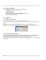
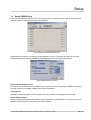
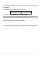
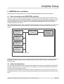
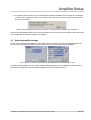
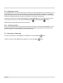
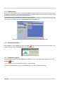
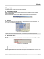
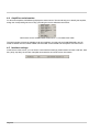
DE-M0321E • DEWEConfig user manual • Software version 5.4.1 • March 10, 2003
Page 1
Page 2
DEWEConfig
Contents
General information
Software version …………………………………………………………………………………………… 5
Warranty agreement ……………………………………………………………………………………… 5
Support information ……………………………………………………………………………………… 7
Using DEWESoft
1 Initial Setup ……………………………………………………………………………………… 9
1.1 About DEWEConfig ………………………………………………………………………………… 9
1.2 Installation …………………………………………………………………………………………… 10
1.3 Setup DEWEConfig ………………………………………………………………………………… 11
2 DEWE-Module installation …………………………………………………………………… 13
2.1
2.2
2.3
2.4
2.5
Basic knowledge about DEWETRON amplifiers …………………………………………………
Module installation tips ………………………………………………………………………………
Selecting amplifier settings …………………………………………………………………………
Saving your setup ……………………………………………………………………………………
New setup / load setup ………………………………………………………………………………
13
13
17
18
18
3 Special functions within DEWEConfig ……………………………………………………… 19
3.1
3.2
3.3
3.4
3.5
Keep modules locked ………………………………………………………………………………
Scan all modules ……………………………………………………………………………………
COM terminal …………………………………………………………………………………………
Version information …………………………………………………………………………………
Terminate program ……………………………………………………………………………………
19
19
20
20
20
4 Some hints ……………………………………………………………………………………… 19
4.1
4.2
4.3
4.4
4.5
Configuration changed ………………………………………………………………………………
Help text ………………………………………………………………………………………………
Red module name? …………………………………………………………………………………
Amplifiers serial number ……………………………………………………………………………
Interface settings ……………………………………………………………………………………
DE-M0321E • DEWEConfig user manual • Software version 5.4.1 • March 10, 2003
19
19
19
20
20
Page 3
DEWEConfig
Page 4
General information
Software version
DEWEConfig Software user manual corresponds with version software version 5.4.1a
Printing notice
Printing version 1.0.1
Release date March 10, 2003
Specifications subject to change without notice.
Copyright notice
© 2003 DEWETRON elektronische Messgeraete Ges.m.b.H. All rights reserved. May not be
duplicated or disseminated in any fashion without the express written permission of Dewetron
Ges.m.b.H.
Trademark notice
All trademarks are acknowledged to be the property of their owners, with all rights and privileges
thereto. No infringement is intended.
Microsoft, Excel and Word are registered trademarks of Microsoft Corporation.
National Instruments is a trademark of National Instruments
Microstar, DAP and iDSC are trademarks of Microstar Labs Inc.
Data Translation is a trademark of Data Translation, Inc.
Disclaimer
Dewetron makes no claim about the efficacy or accuracy of the information contained herein. Use
of this manual is entirely at the user’s own risk. Under no circumstances will Dewetron assume any
liability caused by the use, proper or improper, of this manual or the information, textual, graphical
or otherwise, contained within it.
Warranty agreement
Important - read carefully before installing software. By opening and installing the software you are
agreeing to be bound by the terms of this agreement. This is a legal agreement between you (either
an individual or an entity) and DEWETRON Ges.m.b.H., A-8074 Graz-Grambach (”DEWETRON”).
If you do not agree to all of the terms of this agreement, promptly return the unopened software
packet and the accompanying items (including all written materials) to DEWETRON for full refund.
Limited warranty
DEWETRON warrants that
(a) the Software will perform substantially in accordance with the accompanying written materials
for a period of ninety (90) days from the date of receipt.
(b) the medium on which the software is recorded will be free from defects in material and
workmanship under normal use and service for a period of ninety (90) days from the date of receipt.
DE-M0321E • DEWEConfig user manual • Software version 5.4.1 • March 10, 2003
Page 5
General information
Customer remedies
DEWETRON’s entire liability and your exclusive remedy shall be, at DEWETRON’s option, either
(a) return of the price paid, or (b) repair or replacement of the software that does not meet
DEWETRON’s limited warranty, and which is returned to DEWETRON with a copy of your receipt.
This limited warranty is void if failure of the software has resulted from accident, abuse, or
misapplication. Any replacement software will be warranted for the remainder of the original
warranty period or thirty (30) days, whichever is longer.
No other warranties
Except as expressly set forth above, the software and the documentation are provided “as is”
without warranty of any kind, and no other warranties, either expressed or implied, are made with
respect to the software including but not limited to any implied warranties of merchantability or
fitness or a particular purpose or any other warranties that may arise from usage of trade or course
of dealing. DEWETRON does not warrant, guarantee, or make any representations regarding the
use or the results of the use of the software or the documentation in terms of correctness,
accuracy, reliability, or otherwise and does not warrant that the operation of the software will be
uninterrupted or error free. DEWETRON expressly disclaims any warranties not stated herein.
No liability for consequential damages
The entire liability of DEWETRON is set forth above to the maximum extend permitted by
applicable law, in no event shall DEWETRON be liable for any damages including any special,
direct, indirect, incidental, exemplary or consequential damages, expenses, lost profits, lost
savings, business interrupts, lost business information or any other damages arising out of the use
or inability to use the software or the documentation even if DEWETRON has been advised of the
possibility of such damages.
Page 6
Support
Support information
For any support please contact your local distributor first or DEWETRON directly.
For Asia and Europe, please contact:
DEWETRON Ges.m.b.H.
Parkring 4
A-8074 Graz-Grambach
AUSTRIA
Tel.:
+43 316 3070
Fax:
+43 316 307090
Email: [email protected]
Web:
http://www.dewetron.com
The telephone hotline is available Monday to Friday between 08:00 and 17:00 CET (GMT -1:00)
For the Americas, please contact:
DEWETRON, Inc.
PO Box 1460
Charlestown, RI 02813
U.S.A.
Tel.:
+1 401 364 9464
Toll-free: +1 877 431 5166
Fax:
+1 401 364 8565
Email: [email protected]
Web:
http://www.dewamerica.com
The telephone hotline is available Monday to Friday between 08:00 and 17:00 GST (GMT +5:00)
DE-M0321E • DEWEConfig user manual • Software version 5.4.1 • March 10, 2003
Page 7
Support
Notes
Page 8
Using DEWESoft
Setup
1 Initial Setup
1.1 About DEWEConfig
DEWEConfig is a nice tool to address and configure DEWETRON DAQ and PAD series amplifiers.
1.1.1 DEWEConfig functions
The software supports all new amplifiers, but also older versions. The following table should give you an
overview of the amplifier setting functions:
Module name
Range
Filter
DAQN-DMM
DAQP-DMM
DAQN-V
DAQP-V
DAQP-µV
DAQN-BRIDGE
DAQP-BRIDGE
DAQP-BRIDGE-A
ü
ü
ü
ü
ü
ü
ü
ü
ü
ü
DAQP-BRIDGE-B
ü
ü
DAQP-ACC
DAQP-ACC-A
DAQN-CHARGE
DAQP-CHARGE
DAQP-CHARGE-A
DAQP-CHARGE-B
DAQP-FREQ
DAQP-FREQ-A
DAQN-THERM
DAQN-RTD
DAQN-POT
DAQN-DIFF
DAQN-AIN
PAD-V8
PAD-V8-P
PAD-VTH8
PAD-TH8
PAD-TH8-P
PAD-RTD3
PAD-AO1
PAD-CNT2
PAD-DI8
PAD-DO7
ü
ü
ü
ü
ü
ü
ü
ü
ü
ü
ü
ü
ü
ü
ü
-
ü
ü
ü
ü
ü
ü
ü
-
Additional programmable functions
Half- and quarter bridge completion, excitation voltage, bridge zero, amplifier
zero, shortcut input, shunt calibration, lowpass filter type selection
Half- and quarter bridge completion, excitation voltage, bridge zero, amplifier
zero, shortcut input, shunt calibration, lowpass filter type selection
ICP® / Charge selection, highpass filter, integration: none, single, double
Trigger level selection, find trigger level, AC/DC coupling, fast/slow output filter
Recognition of thermocouple type with PAD-CB8-x-P connector
DEWEConfig will be updated continuously to recognize new amplifiers and to support new amplifier firmware
versions.
If your amplifiers don’t have above mentioned functions, please contact DEWETRON.
DE-M0321E • DEWEConfig user manual • Software version 5.4.1 • March 10, 2003
Page 9
1.1.2 System requirements
To achieve a good performance, we recommend the following hardware:
WINDOWS 98 / ME / NT4.0 / 2000 / XP
Intel Pentium processor
128 MB RAM or higher
Approx. 2 MB free harddisk space for DEWEConfig
DEWETRON system with installed DAQ and PAD series amplifiers,
connected to the RS-232 interface
1.2 Installation
1.2.1 DEWEConfig installation
To install DEWEConfig, just follow the instructions of the installation shield.
DEWEConfig will be installed automatically in the following directory: C:\DEWETRON\Program\DEWEConfig
After installation, you may start DEWEConfig directly from the Windows desktop using the
DEWEConfig icon. During the startup, you will see the following window showing the current software version:
DEWECONFIG VERSION INFORMATION
1.2.2 Installing DEWEConfig updates
Please follow the installation instructions of the readme files, which are included with any update version.
Updates are available on the DEWETRON web server http://www.dewetron.com, but you can also download
them directly from the FTP server ftp://ftp.dewetron.com/public/software/deweconfig.
You should always use the latest version to avoid any problems. The DEWEConfig software can be downloaded
free of charge.
Page 10
Setup
1.3 Setup DEWEConfig
When you start DEWEConfig for the first time, you have to do a few basic settings. As soon as the software
has been loaded completly, the following screen appears:
MAIN DEWECONFIG WORKING PLACE
Depending on the system, it can already contain amplifiers. Anyway, you should have first a look into the
DEWEConfig settings. Just select Setup from the System menu to open the following window:
BASE DEWECONFIG SETTINGS
System setting: Number of slots
Use this function to define how much amplifiers your system may have. For example, a DEWE-2010 system
normally contains 16 amplifiers, a DEWE-3010 system 8 amplifiers.
Language file
Select the software language out of the dropdown list. As a standard, the language is set to English.
Special DAQP settings
Use the lock buttons with PowerOnDefault to lock the push buttons on the amplifiers - even after power loss.
Be aware that this function is not working with older amplifiers.
DE-M0321E • DEWEConfig user manual • Software version 5.4.1 • March 10, 2003
Page 11
Com port settings
This is the most important selection, because it defines the serial port where the amplifiers are connected. The
value depends from system to system, as a standard, it is set to COM1.
DEWETRON System
DEWE-Module Com Port*
DEWE-3010, DEWE-3000, DEWE-4000
DEWE-2010, DEWE-2000
DEWE-RACK, DEWE-BOOK
COM 2
COM 1
According to your PC or notebook
Be aware that the number of the COM port might vary from system to system.
Attention: please check this to ensure that you have the correct com port, as incorrect settings can cause
your system to hang up, or disable other devices that are already using the same com port.
General information
This part is generally just for information - don’t try to change anything, otherwise the system may not work
properly any more. It is just available for special high-speed systems.
If you have changed anything and the system is not working any more, press the Restore Defaults button to
restore the default settings.
After changing the parameters, press the OK button to confirm changes or press Cancel to reject changes.
Page 12
Amplifier Setup
2 DEWE-Module installation
DEWEConfig is the base software tool to configure all DEWETRON DAQ and PAD series amplifiers.
2.1 Basic knowledge about DEWETRON amplifiers
First of all, you have to know that all DAQP and PAD series amplifiers have a build-in RS-485 interface. This
interface is used to communicate with the amplifiers. The reason for the RS-485 interface was simple: you can
connect multiple ‘devices’ on one bus with nearly no limitation in cable length. To identify each device (in our
case each amplifier), it receives an address. In case of the DEWETRON amplifiers, the module address
corresponds with the slot number.
Within DEWETRON systems, there is a RS-485 to RS-232 interface converter. For that reason, you don’t have
to worry about the RS-485 interface and simply communicate through one of the selected com ports (e.g.
COM1).
DAQP- or
PAD module
Address 0
RS-485
RS-232
DEWETRON
System or
PC / Notebook
with DEWESoft
DAQP- or
PAD module
Address 1
DAQP- or
PAD module
Address 2
DAQP- or
PAD module
Address 3
Further modules
SCHEMATIC OVERVIEW OF THE ADDRESS CONCEPT
DEWEConfig assigns the slot numbers as addresses to the amplifiers and allows also some base settings of
the amplifiers. There are different ways to assign the address to the amplifiers, which are described in the
following section.
2.2 Module installation tips
You can install your DAQP and PAD modules (and any DAQN module that has a small black button near the
top of the module) all at once, or if you replace just one module, you can also replace just one module in the
software without installing them all again.
Let's look at the initial installation of all modules. Please note that this is done for you when you receive your
DEWETRON system, but if you change modules around frequently, this procedure will be very useful for you to
know.
DE-M02A1E • DEWESoft user manual • Software version 5.4 • October 30, 2002
Page 13
First, please do not try to do this unless you:
1) Really have DAQP, PAD, or certain DAQN modules connected to this system!
2) Have set up the com port properly in accordance with the instructions in this manual
The reason for this precaution is simple: when you tell DEWEConfig to scan for your modules, it will use the
com port previously defined. If there are no modules on that port, or some other device in your computer is
currently using that com port, it will hang up your computer! Please proceed only if you are really using a
DEWETRON system with DEWE-Modules.
2.2.1 Using the Fill Rack function to add modules
When your com port is properly set as described above, you can start the effective FillRack procedure.
If you have any PAD modules without the small black button near the top of the module in your system, please
do something FIRST:
Select the Reset PAD Modules item from the System menu and confirm the warning message.
Then unscrew the modules and pull them slightly out of the rack, so that their green LED's turn out. You will be
instructed when to reinsert them, one at a time, in a moment.
Now select the FillRack from the System menu or press the
button. The following screen will appear:
THE FILL RACK COMMAND ALLOWS AN EFFICIENT MODULE INSTLLATION
DEWEConfig now asks you to either press the top black button or reinsert the PAD module into each slot, one
at a time, starting with slot 0. A system beep confirms the pressed button.
Page 14
Amplifier Setup
After the module has been recognized, it will be displayed in the list and DEWEConfig asks you for the
amplifier in slot 1.
RECOGNIZED AMPLIFIER IN SLOT 0, MORE TO COME...
If you do not have a DAQP module, PAD module, or DAQN module with a small black button near the top of the
module in any slot, or if this is an empty slot, simply click the Skip button and it will move to the next module.
When you are done, click the Finish button.
2.2.2 Replacing just one module
You can replace just a single module without having to run the FillRack function and start all over again. This is
convenient when you have just swapped one or two modules out in order to do a certain test, and you do not
want to enter in the input names, scaling, and re-run the calibration on the unchanged channels.
If you are installing a new/replacement DAQP series module, plug the module in. If you are installing a PAD
series module, the process is a little more involved, and we will cover that second.
Installing just one DAQP series module
1. Remove the module that you are replacing, or the blank panel from the slot that you wish to plug your
new/replacement module into.
2. Install the DAQP series module into this slot.
3. Double-click on the name of the module, which is the AMPLIFIER column:
DOUBLE-CLICK ON THE NAME OF THE MODULE, LIKE "DAQP-DMM" IN THE EXAMPLE ABOVE
4. and the software will ask you a question on the screen: WHAT SHOULD BE DONE WITH THIS
MODULE? With three choices: Fill, Clear, or Cancel. Fill allows you to add your new module. Clear
removes any module from this slot. Cancel leaves here without making any changes. Click Fill to add
your new module.
CLICK FILL TO ADD YOUR NEW MODULE...
5. The software will now instruct you to press the top black button on the new DAQP module. When you do
this, it will recognize it and add it into this slot on the screen.
PRESS THE TOP BLACK BUTTON ON THE NEW MODULE, OR CANCEL TO LEAVE WITHOUT
MAKING ANY CHANGES
DE-M02A1E • DEWESoft user manual • Software version 5.4 • October 30, 2002
Page 15
6. Now just click the SETUP button for this slot and configure it as you would any other module. Notice
that your configuration for the other modules is unchanged!
Installing just one DAQN or DAQ series module, or NONE
If you are replacing a DAQP series module or PAD series module with a non-programmable type, simply
double-click the name of the DAQP module that you want to remove/replace, and then select Clear from the
prompt that will appear. This will remove the programmable module from this slot and will display Direct input.
Now just click the Set ch x button for this slot and then manually tell the software which non-programmable
module you wish to add to this slot and select the correct input range.
Detailed information about input ranges of the DAQ / DAQN series modules is available in the DEWE-Modules
technical reference manual, shipped together with your system.
SELECT THE NON PROGRAMMABLE AMPLIFIER OUT OF THE DROP-DOWN LIST
Installing just one PAD-V8-P or PAD-TH8-P module
Perform the same steps then Installing just one DAQP series module. This is possible, because the
PAD-V8-P and PAD-TH8-P modules have the black push button.
Installing just one other PAD series module
If the PAD module that you wish to install is already set to address 0, then the process is simple:
1. Remove the module that you are replacing, or the blank panel from the slot that you wish to plug your
new/replacement module into.
2. DO NOT INSTALL THE PAD MODULE YET!! Get it ready, but do not plug it in. If it is a PAD-VTH8
module, you must have the mating connector already plugged into it, otherwise it will not be recognized
properly. PAD-TH8 and other PAD modules do not have this requirement - only the PAD-VTH8.
3. Double-click on the name of the module, which is the AMPLIFIER column:
DOUBLE-CLICK ON THE NAME OF THE MODULE, LIKE "PAD-TH8-P" IN THE EXAMPLE ABOVE
4. and the software will ask you a question on the screen: WHAT SHOULD BE DONE WITH THIS
MODULE? With three choices: Fill, Clear, or Cancel. Fill allows you to add your new module. Clear
removes any module from this slot. Cancel leaves here without making any changes. Click Fill to add
your new module.
CLICK FILL TO ADD YOUR NEW MODULE...
Page 16
Amplifier Setup
5. The software will now instruct you to insert the PAD module with address 0 into this slot (in our example
it is slot 0, but it could be any slot in your system). When you do this, it will recognize it and add it into
this slot on the screen.
INSERT YOUR PAD MODULE, OR CLICK CANCEL TO LEAVE WITHOUT MAKING ANY CHANGES
Now just click the Set ch x button for this slot and configure it as you would any other PAD module. Notice that
your configuration for the other modules is unchanged!
2.3 Selecting amplifier settings
Now let's look at the amplifier settings. As all modules are now installed, just click on the Set ch x button all
the way on the right side of the table, for that amplifier. When you do, a settings dialog will appear:
THE CONTENT OF THE SETTINGS DIALOG BOX DEPENDS ON THE AMPLIFIER TYPE
As the functionallity depends on the module, also the settings dialog box will look different for each module. A
short function description of each module is available in the overview table in section 1.
DE-M02A1E • DEWESoft user manual • Software version 5.4 • October 30, 2002
Page 17
2.4 Saving your setup
That's all there is to it - all of your modules have now been set to the same address as the slot that they are in!
It is prudent to stop right now and save this setup as something called "Default" or "Modules," or something
easy to remember, as it can serve as a nice starting point for any number of setups. Setups are automatically
stored in the \Setups subdirectory, and given an extension of .DCs (Dewe Config setup).
The setup can be stored in the File - Save Setup menu. Save Setup As can be used if you want to give the
current setup a new name. Or simply press the Save Setup
or Save Setup As
buttons.
DEWEConfig will always start with the last stored setup.
2.4.1 Autostore function
When you leave DEWEConfig, all settings will be stored automatically in a setup file called last.DCs. This file
is some kind of backup, for example if you forgot to store the changes, they won’t be lost. When you start
DEWEConfig again, it reads the settings out of the last.DCs file.
2.5 New setup / load setup
To create a new setup, just select New from the File menu or press the New
To load a new setup, select Open from the File menu or press the Open
Page 18
button.
button.
Special Functions
3 Special functions within DEWEConfig
DEWEConfig offers a few small, but helpful functions.
3.1 Keep modules locked
During the configuration within DEWEConfig, all push buttons on the amplifiers are locked. The only way to
change settings is through the software. As soon as you leave DEWEConfig, the push buttons are working
again.
If you want to avoid unauthorized or inadvertently activities on the push buttons after leaving DEWEConfig, you
should activate the function keep modules locked on Exit of DEWEConfig. This will lock the push buttons.
You have to enter DEWEConfig again and deactivate this function to get access to the push buttons again.
‘LOCKED MODULES’ ACTIVATED
3.2 Scan all modules
With the ScanAllModules command in the System menu, DEWEConfig is looking through the whole system
for any amplifiers, connected to the system. The result is a nice overview of the current modules and settings.
SETTINGS SUMMARY OF ALL DEWETRON MODULES IN THE SYSTEM
DE-M0321E • DEWEConfig user manual • Software version 5.4.1 • March 10, 2003
Page 19
3.3 COM terminal
The COM terminal allows to send commands to all DAQP and PAD amplifiers and can also be used to check
the serial communication. Any commands mentioned in the DEWE-Modules technical reference manual can be
entered here for direct communication with the amplifiers.
ATTENTION: Wrong commands can disturbe the whole system!
To enter the com terminal, just select ComTerminal from the System menu.
COM TERMINAL EXAMPLE SHOWING INFORMATION OF A DAQP-DMM MODULE
3.4 Version information
Select About... from the Help menu or press the Info
button to get the software version information. The
software version number will be required for any support requests.
3.5 Terminate program
To terminate the program, just select Exit from the File menu, click on the WINDOWS close button or press
the Exit
button.
If you close the software, the last.DCs file will be created / updated.
To start the software again, just click on the DEWEConfig icon on the WINDOWS desktop.
Page 20
Hints
4 Some hints
In the following section you find a few hints for using DEWEConfig.
4.1 Configuration changed
Maybe you have already recognized it, but there is a small sign which indicates that you have changed
anything in the configuration.
As soon as there are any changes, a * will be added to the setup file name in the top of the window.
* INDICATES CHANGES IN THE SETUP
4.2 Help text
No idea about the function of any button? No problem. Just move the mouse over it and wait a second - then
you will get a short message about the button function.
HELP FUNCTION FOR EACH BUTTON
Attention: This function is still under development, some buttons may not contain the help function.
4.3 Red module name?
The is a red colored module name in the amplifier list? This is a warning and means that anything is wrong with
this entry.
EXAMPLE WITH THREE ERRORS
Possible errors:
The module has been removed from the system
There is an address conflict with another module
There has been an communication problem with the module
To solve the problem, double click on the entry and Clear or Fill the entry (see also chapter 2). If the error is still
mentioned, try the FillRack function. If the error is still displayed, contact DEWETRON.
DE-M0321E • DEWEConfig user manual • Software version 5.4.1 • March 10, 2003
Page 19
4.4 Amplifiers serial number
For all newer amplifiers, DEWEConfig displays the serial number. This should help you to identify the amplifier,
assign the corresponding sensors or help you finding the correct calibration information.
AMPLIFIERS SERIAL NUMBER MENTIONED NEXT TO THE AMPLIFIER NAME
The serial number will soon be available for all new amplifiers. Currently only the DAQP-BRIDGE-A and -B,
DAQP-CHARGE-A and -B, DAQP-FREQ-A and the PAD-V8-P and PAD-TH8-P amplifiers use this function.
4.5 Interface settings
At the bottom of the screen, you can see the current interface settings (serial interface number, baud rate, data
bits, parity, stop bits), the number of amplifier slots and also an internal version information.
Page 20