1
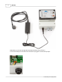
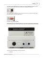
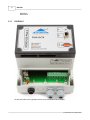
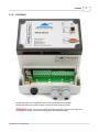
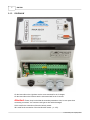
838 PNA
User Manual
power.dewetron.com
The information contained in this document is subject to change without notice.
DEWETRON Elektronische Messgeraete Ges.m.b.H. (DEWETRON) shall not be liable for
errors contained in this document. DEWETRON MAKES NO WARRANTIES OF ANY KIND
WITH
REGARDS TO THIS DOCUMENT, WHETHER EXPRESS OR IMPLIED. DEWETRON
SPECIFICALLY DISCLAIMS THE IMPLIED WARRANTIES OF MERCHANTABILTIY AND
FITNESS FOR A PRACTICULAR PURPOSE. DEWETON shall not be liable for any direct,
indirect, special, incidental, or consequential damages, whether based on contract, tort, or
any
other legal theory, in connection with the furnishing of this document or the use of the
information in this document.
Restricted Rigths Legend:
Use Austrian law for duplication or disclosure.
DEWETRON elektronische Messgeraete GesmbH
Parkring 4
A-8074 Graz-Grambach / Austria
http://www.dewetron.com
Copyright © DEWETRON
elektronische Messgeraete Ges.m.b.H.
This document contains information which is protected by copyright. All rights are resreved.
Reproduction, adaption, or translation without prior written permission is prohibited, except
as allowed under the copyright laws. All trademarks and registered trademarks are
acknowledged to be the property of their owners.
Contents
I
table of contents
Part I presentation of instruments
1
Part II hardware
2
1 installation
838-PNA-V
838-PNA-P
838-PNA-W
................................................................................................................................... 2
..........................................................................................................................................................
..........................................................................................................................................................
..........................................................................................................................................................
5
6
7
2 status bar
................................................................................................................................... 8
3 MLI
................................................................................................................................... 8
4 mounting possibilities
................................................................................................................................... 9
wall mounting..........................................................................................................................................................
counter panel..........................................................................................................................................................
mounting
DIN rail
..........................................................................................................................................................
10
10
11
5 technical data
................................................................................................................................... 13
Part III software
14
1 viewing the data
...................................................................................................................................
online
14
numeric values
..........................................................................................................................................................
vectorscope ..........................................................................................................................................................
FFT
..........................................................................................................................................................
16
18
19
2 configuration................................................................................................................................... 23
starting and stopping
..........................................................................................................................................................
the measurement
network settings
..........................................................................................................................................................
transducer factors
..........................................................................................................................................................
and transducers
PNA-838-V
.........................................................................................................................................................
PNA-838-P
.........................................................................................................................................................
PNA-838-W
.........................................................................................................................................................
alarms and fault
..........................................................................................................................................................
records
calculated values
..........................................................................................................................................................
time synchronisation
..........................................................................................................................................................
of the measuring instrument
upgrading the..........................................................................................................................................................
firmware
25
27
29
29
30
32
33
34
36
37
3 transferring data
................................................................................................................................... 38
manual transmission
..........................................................................................................................................................
of data
view current
.........................................................................................................................................................
data
status of the
.........................................................................................................................................................
data transfer
remote access
.........................................................................................................................................................
for maintenance
automatic transmission
..........................................................................................................................................................
of data
39
41
41
42
43
4 data evaluation
...................................................................................................................................
with PMT
43
Index
0
© 2010 Enter your company name
I
1
1
838 PNA
presentation of instruments
The instrument line 838-PNA has especially been developed for measurements in electrical power
grids. The instrument does not have a ventilator which allows the installation in various environments.
Its high EMC resistance makes it possible to use this instrument in all network levels.
The model is available in 3 different versions:
model
838-PNA-V
PNA-838-P
PNA-838-W
usage
power quality
measurements
power measurements and
power quality
power and power quality in
wind energy plants
voltage input
electricity input
other input channels
4
-
4
4
3
3
wind velocity, wind
© 2010 Enter your company name
presentation of instruments
2
direction
measured values
U
I
P, Q, S, PF, cos Phi
Q
frequency
harmonics U
harmonics I
harmonics power
flicker (PSt, Plt)
unbalance
fault recorder
wind velocity, wind
direction
2
x
x
x
x
x
x
x
x
x
x
x
x
x
x
x
x
x
x
x
x
x
x
x
x
x
x
x
x
x
x
x
hardware
This chapter gives you hints and explanations to the following topics:
installation of the measuring instrument
status bar
automatic measurement location identification (MLI)
installation possibilities
technical data
2.1
installation
Connect the power supply with the measuring instrument and plug the power supply into the power
outlet.
© 2010 Enter your company name
3
838 PNA
Alternatively, you can also energize the instrument with direct current: DC 24 V
This one can directly be connected to the instrument or plugged in via the black input jack.
© 2010 Enter your company name
hardware
4
The network connector NET serves as a connection to a network (Ethernet). Be advised to use this
one for the transfer of data either online onto a server or manually onto a notebook.
The connection COM is designed for service purposes and serves as a connection to the PC via a
serial cable (RS232) and a terminal programme.
Connection of the measuring signals:
Open the lower cover of the measuring instrument set to the bottom. With the help of measuring lines
the measuring signals are brought into the measuring instrument via waterproofed screw connections.
The kind of connection depends on the type of instrument:
838-PNA-V
© 2010 Enter your company name
5
838 PNA
838-PNA-P
838-PNA-W
2.1.1
838-PNA-V
On the lower side on the right there are the screw terminals for the 4 voltages.
© 2010 Enter your company name
hardware
2.1.2
838-PNA-P
On the lower side on the right there are the screw terminals for the 4 voltages.
On the lower side on the left there are the screw terminals for the 4 currents.
Attention! Please, keep in mind that the secondary transducer circle is never open when
connecting converters - the converter could get too hot and be damaged!
© 2010 Enter your company name
6
7
2.1.3
838 PNA
838-PNA-W
On the lower side on the right there are the screw terminals for the 3 voltages.
On the lower side on the left there are the screw terminals for the 3 currents.
Attention! Please, keep in mind that the secondary transducer circle is never open when
connecting converters - the converter could get too hot and be damaged!
UN is used for the connection of the wind velocity sensor.
IN is used for the connection of the wind direction sensor. (+/- 10V).
© 2010 Enter your company name
hardware
2.2
8
status bar
On the upper side of the instrument there is a LED which shows the status of the instrument.
The LED can have the following colours:
dark
the instrument is not activated
red
the instrument is booting
blinking the instrument is ready for use, configuration
red
mode
green the instrument is measuring and has not saved
any data yet
blinking the instrument is measuring and has already
green saved the data
2.3
MLI
In the opening for the screw terminals you find a USB jack on the left which is designed for the MLI
technology. MLI means Measurement Location Identification.
Every measurement location is assigned to a USB jack. On this one the measuring instrument saves
all the settings. If an instrument is exchanged, then the USB jack has to be exchanged as well. The
configuration of the old instrument is automatically transferred to the new one. The measurement can
then be continued without interruption and without having to perform a configuration of the
measurement or the network settings.
© 2010 Enter your company name
9
2.4
838 PNA
mounting possibilities
Basically, the instrument has to be mounted upright and onto a plane wall.
You can choose between the following possibilities to mount the instrument:
wall mounting
counter panel mounting
DIN rail
© 2010 Enter your company name
hardware
2.4.1
10
wall mounting
For wall mounting there are several holes on the bottom of the box
2.4.2
counter panel mounting
For mounting on a counter panel use the holes on the bottom and the screw hole in the middle upper
part.
© 2010 Enter your company name
11
2.4.3
838 PNA
DIN rail
For mounting on a DIN rail insert the springs on the back side.
© 2010 Enter your company name
hardware
© 2010 Enter your company name
12
13
2.5
838 PNA
technical data
© 2010 Enter your company name
software
3
14
software
The 838-PNA does not need any special software for its operation and configuration.
Start your web browser and insert your name and IP number of the instrument in the address bar.
In our case: pna838. dewetron.com
Insert the username and password in the following window:
Usually:
username: "viewer" with password "viewer" .... in order to view the data
username: "admin" with password "admin" ... in order to view the data and set up the instrument
Further features of the instrument:
data transfer
data analysis
3.1
viewing the data online
When you are logged in as "viewer", you get the following start screen:
© 2010 Enter your company name
15
838 PNA
There you have the following possibilities:
...you get to the start screen
...you get to the measured data and obtain the following submenu:
RMS...displays the measured values as numeric values
Vectorscope....the vectorscope of voltages and current
FFT...the various harmonics
...you log out and get to the log in menu
© 2010 Enter your company name
software
3.1.1
numeric values
Online you receive the following values:
f...frequency
u2_1...value of unbalance
P...total active power
Q...total reactive power
S...total power
U L-E...phase voltage (line to earth)
U L-L...line voltage (line to line)
I...currents
P...active power per phase
Q...reactive power per phase
S...total power per phase
P H1...fundamental active power per phase
Q H1...fundamental reactive power per phase
Phi UI...angle between voltage and current
Phi UU...angle of voltages to the fundamental of the first phase
Pst...short-term flicker (IEC 61000-4-15)
THD...total harmonic distortion
THD even...total harmonic distortion of the even harmonics
THD odd...total harmonic distortion of the odd harmonics
© 2010 Enter your company name
16
17
838 PNA
Depending on the type of instrument the presentation of data can vary.
Thus, the PNA-V lacks the values of current and power.
The type PNA-W also shows the wind direction and velocity.
© 2010 Enter your company name
software
3.1.2
vectorscope
On the vectorscope voltages and currents can be viewed as vectors.
Additionally, you receive the RMS values and the corresponding angles.
© 2010 Enter your company name
18
19
3.1.3
838 PNA
FFT
The FFT diagram shows the harmonics.
The calculation of these values is done according to the harmonics standard IEC 61000-4-7.
Voltages, currents and power can be illustrated:
FFT U: FFT of voltages
© 2010 Enter your company name
software
FFT I: FFT of currents
© 2010 Enter your company name
20
21
838 PNA
FFT UI: FFT of voltages (top) and currents (bottom)
© 2010 Enter your company name
software
FFT P: FFTof active power
The following diagram shows that, in this case, positive power is drawn above zero and negative
power is drawn below zero.
© 2010 Enter your company name
22
23
3.2
838 PNA
configuration
When you are logged in as "administrator" (admin) you see the following start screen depending on the
status of the instrument (measurement started/stopped):
© 2010 Enter your company name
software
The individual buttons offer the following functions:
...to the start menu (above)
...to the online diagram of the data
...network settings
© 2010 Enter your company name
24
25
838 PNA
...settings of the transducer and transducer factors
...alarms and fault records
...configuration of different measurement values
...you log off and get to the login menu
...start or stop the measurement
...synchronisation of the time on the measurement instrument
...upgrading the firmware
3.2.1
starting and stopping the measurement
On the login screen you have the possibility to stop the measurement when it has been running (see
window below) or start the measurement when it was stopped before (second window).
© 2010 Enter your company name
software
In both cases you can synchronise the time with the clock of the PC:
When the measurement was stopped you can upgrade the firmware:
© 2010 Enter your company name
26
27
3.2.2
838 PNA
network settings
The network settings are made according to TCPIP common standards whereas you can insert
network name or network address in the fields.
© 2010 Enter your company name
software
28
DHCP: if you want to use DHCP, this field must be chosen
hostname: network name of your measuring instrument
IP address: network address if you do not use DHCP
IP mask: network mask
default gateway: your gateway in the network
DNS 1: domain name system 1
DNS 2: domain name system 2
NTP server: network time server (see time synchronisation of the measuring instrument)
data server: PMT server if you want totransfer the data automatically
activate data transfer: this boy must be chosen in order to have the data automatically transferred
save: saves the settings (generally new settings are taken over after restarting the measurement)
© 2010 Enter your company name
29
3.2.3
838 PNA
transducer factors and transducers
If transducers are used together with the measuring instruments, you can list them here.If no
transducers are used, the setting remains 1 or 0 respectively for the offset.
Depending on the type of instrument the settings are different:
PNA-838-V
PNA-838-P
PNA-838-W
3.2.3.1
PNA-838-V
If voltage transducers are used, you can list them here:
If no voltage transducers are used, the setting remains 1 or 0 respectively for the offset.
© 2010 Enter your company name
software
30
primary scale: the primary voltage of the transducer
secondary scale: the secondary voltage of the transducer
offset: a possible offset
example:
transducer 20 kV / 100 V
primary scale: 20000
secondary scale: 100
offset: 0
save: saves the settings (generally new settings are taken over after restarting the measurement)
3.2.3.2
PNA-838-P
© 2010 Enter your company name
31
838 PNA
If voltage transducers or current transducers are used, you can list them here:
If no voltage or current transducers are used, the setting remains 1 or 0 respectively for the offset.
primary scale: the primary voltage of the transducer
secondary scale: the secondary voltage of the transducer
offset: a possible offset
example:
transducer 20 kV / 100 V
primary scale: 20000
secondary scale: 100
offset: 0
save: saves the settings (generally new settings are taken over after restarting the measurement)
© 2010 Enter your company name
software
3.2.3.3
32
PNA-838-W
If voltage transducers or current transducers are used, you can list them here:
If no voltage or current transducers are used, the setting remains 1 or 0 respectively for the offset.
primary scale: the primary voltage of the transducer
secondary scale: the secondary voltage of the transducer
offset: a possible offset
example:
transducer 20 kV / 100 V
primary scale: 20000
secondary scale: 100
offset: 0
© 2010 Enter your company name
33
838 PNA
For the wind parameters you have to list the scaling and a possible offset:
wind speed: the sensor scaling in m/s / V
offset: in m/s
wind direction: the sensor scaling in degree / V
offset: in V
save: saves the settings (generally new settings are taken over after restarting the measurement)
3.2.4
alarms and fault records
Here the settings for the fault recorder functions can be made:
Teh functions of the parameters are:
© 2010 Enter your company name
software
34
a) storage time: the duration of the record in case of a fault
Pretime: the time of record BEFORE the fault happened in ms: here 1000ms = 1 second
Posttime: the time of record AFTER the fault ended in ms: here 3000ms = 3 seconds
Max. trigger time: the maximum storage time of a fault in ms: here 10000ms = 10 seconds
Posttime extension: If this box is checked and if a new fault happenes during the posttime the counting
of the posttime starts again. The maximum duration (max trigger time) will stay the same.
b) trigger storage: how the data shall be stored
no values: no data are stored, but the event of start and stop of the fault.
10 ms RMS values: the half period values (RMS, AVG) are stored (e.g. 10ms @ 50Hz)
raw data: all data in the original sampling speed are stored (10 kHz)
c) limits: the limits which cause a fault record
relative/absolute: in general there is a difference between relative data (% of nominal voltage) and
absolute data (in V)
For the recording of a voltage band event (window trigger) the following data are required:
Start limit: The start limit for the fault recording.
Stop limit: The stop limit for the fault recording
Upper Limit: The upper limit (over voltage, swell)
Lower Limit: The lower limit (voltage sag)
For the recording of a rapide voltage change (RVC, rms to rms value) the following data are required:
voltage variation: the value of the maximum allowed voltage change. The recording is stopped
immediately after the event (plus posttime).
save: saves the settings (generally new settings are taken over after restarting the measurement)
3.2.5
calculated values
Here is to define which data shall be calculated and how they shall be stored.
© 2010 Enter your company name
35
838 PNA
Instrument ID: a number, which will be used later in the post processing software (PMT) for
identification of the data. This number must be UNIQUE for each instrument Module Name: The name
of the measurement, which ill be used later in the evaluation software (e.g.: feeder line, location,...)
Grid type: The connection schematic
1 phase: single phase
3 phase star: 3 phase star (typically in the low voltage grid)
3 phase delta: 3 phase connection in star, but evaluation in delta (typically in medium and high voltage
grids)
Nominal voltage: Nominal value of the voltage
Nominal frequency: Nominal value of the frequency
Number of cycles: Number of cycles for the harmonics calculation (typically 10 according the
harmonics standard IEC 61000-4-7)
save currents: if currents shall be measured as well (only -P and -W version).
Ue Ie: if the 4th phase shall be measured as well (neutral voltage and current, only -P Version)
© 2010 Enter your company name
software
36
Harmonics: if harmonics shall be calculated and stored as well (according IEC 61000-4-7)
THD: Total Harmonic Distortion. The number defines up to which harmonic the calculation shall be
made (40 according the standard)
Phase Angle: if phase angles of harmonics shall be stored.
P, Q: if active and reactive power of harmonics shall be stored.
Interharmonics: if interharmonics shall be stored.
Impedance: if load impedances of harmonics shall be stored.
Flicker:if flicker shall be calculated and stored. (according IEC 61000-4-15)
Pst time: duration of the short term flicker (10 minutes according the standard)
Plt time: duration of the long term flicker (2 hours = 12 Pst values... according the standard)
storage interval [s]: storage interval of the data (typically 600 seconds)
f. storage interval [s]: storage interval of the frequency data (typically 10 seconds)
at rounded time stamps: if data shall be stored at multiples of full hours (storing exactly at 12:00,
12:10, 12:20 etc.. according IEC 61000-4-30 Class A)
signal voltages: if signal voltages shall be calculated.
Frequency: Signal frequency in Hz.
storage interval: storage interval of the signal voltages (typically 3 seconds)
save: saves the settings (generally new settings are taken over after restarting the measurement)
3.2.6
time synchronisation of the measuring instrument
The instrument can be synchronised to a reference time in two different ways:
1) manual during connection with the web browser:
(recommended for not permanent installed instruments)
If you are logged in as administrator you will find the following information on the start screen about the
time settings on the instrument:
Click on "write browser time to instrument" to synchronise the time from your computer to the
instrument.
2) with a network time server (NTP)
(recommended for permanent installed instruments)
In large networks or also in the internet there are several time servers available. They can be queried
via NTP (network time protokoll).
In the general Network settings you can define the time server and then instrument is permanently
synchronised to this time source.
© 2010 Enter your company name
37
3.2.7
838 PNA
upgrading the firmware
For upgrading the firmware please follow these steps:
1) copy the upgrade file to your computer (where the web browser is started)
2) connect to the instrument as administrator
3) if the measurement is running stop it
4) at the start page you will find the following part:
5) click on "File uploaden"
6) define the file to upload
© 2010 Enter your company name
software
38
7) click on "Upload starten"
8) Go back to the overview
9) restart the measurement
The measurement starts with the new firmware.
3.3
transferring data
For the data transfer there are two possibilities:
Manually
Automatically
© 2010 Enter your company name
(for instruments without a network connection to a PMT-Server)
(for instruments with a permanent network connection to a PMT-Server)
39
3.3.1
838 PNA
manual transmission of data
For the manual transfer of data you have to install the programme "dataloader" on the computer from
which the data should be queried.
After starting the programme the following screen appears:
The menu in detail:
...shows the status of the data transfer, e.g. which data have been transferred
...shows the current data that are being measured on the measuring instrument
...you have to insert the IP address or the network name of the
measuring instrument which should be queried
...you have to insert the local data directory in which the data should
be buffered
...server name or network name of the PMT server (Appserver).
© 2010 Enter your company name
software
40
...starts the data transfer from the measuring instrument to the local computer. The
status is shown in the window below.
...In order to speed up the data transfer the measuring instrument packs the
data into an archive file every 6 hours. When this option is chosen, only these archives are
transferred. The last 6 hours at the maximum remain on the measuring instrument (increased
performance for long-term measurements).
...starts the data transfer from the local computer to the PMT server. The status is
again shown in the window below.
...carries our the data transfer from the measurement instrument to the computer and
further on to the server in one go
...In order to speed up the data transfer you have the possibility to merge
the data files. When having a lot of small measurement data files you can speed up the data transfer
to the database.
....deletes the data on the instrument that have already been transferred
....deletes all data files on the measuring instrument
...opens a tellnet session with the measuring instrument
...restarts the measuring instrument
© 2010 Enter your company name
41
3.3.1.1
838 PNA
view current data
In this window the actual data of the instrument are shown.
3.3.1.2
status of the data transfer
In this window the status of the transfer is shown. In this example two sets of data have been
transferred.
© 2010 Enter your company name
software
3.3.1.3
42
remote access for maintenance
With the help of a tellnet session system commands can be carried out on a measuring instrument
Attention: Only catty out this operation if you exactly know what to do - you can otherwise damage the
measuring instrument.
© 2010 Enter your company name
43
3.3.2
838 PNA
automatic transmission of data
For the automatic transmission of data you have to arrange the following settings in the network
settings:
data server ... the network address or the name of the PMT server (AppServer)
activate data transfer ... activates the automatic transfer of data to the PMT server
3.4
data evaluation with PMT
The evaluation of data is carried out with the provided software package PMT.
© 2010 Enter your company name
software
44
Please, find a detailed description as regards operation and handling in our manual and on the Power
Home Page respectively.
Under the following link:
http://power.dewetron.com/html/Manuals/PMT4_e/index.html
© 2010 Enter your company name