1
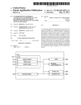
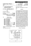
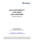
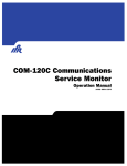
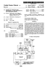
US005717691A
United States Patent [19]
[11]
Patent Number:
Dighe et a1.
[45]
Date of Patent:
[54] MULTIMEDIA NETWORK INTERFACE FOR
ASYNCHRONOUS TRANSFER MODE
COMMUNICATION SYSTEM
5,717,691
Feb. 10, 1998
OTHER PUBLICATIONS
Stuart Wray et al. ‘The Medusa Applications Environment.”
to appear in the Proc. of the Int'l. Conf. On Multimedia
Computing and Systems. Boston. MA. May 1994.
[75]
Invent“:
Joel E Adam a al. “A Network Architecture for Distributed
Raychaudhu? ‘Princeton inaction an
Multimedia Systems." in Proc. of IEEE 18th Annual Conf.
of N J
on Local Computer Networks. Minneapolis. MN. Sep. 1993.
’
‘
' '
pp. 70-76.
73 Assi nee: NEC USA Inc" Pri 06mm NJ.
[ l
g
’
n
NEC MOS Integrated Circuit pPD98401 Local ATM SAR
Chip-Preliminary Data Sheet. Jun. 1994.
_
NEC nPD98402 Local ATM Sonet Framer User’s Manual.
[21] Appl. No.. 550,330
[22] Film:
Oct- 30’ 1995
[511
May 1996“
Primary Examiner-Douglas W. Olms
Im. 01.6 ................................................... .. H04L 12/56
“Si-‘"1"’ ‘WWW-‘Ricky Q‘ Ng°
[52] us. (:1. ......................... .. 370/401; 370/463; 370/466
“0'7"? 45'6"" 0’ Firm-“?ery 1' Bmscmer" Arthur 1'
[581
Tm‘ghc“
Field of Search ................................... .. 370/389. 392.
370/395. 396. 397. 401. 463. 465. 466.
469' 474‘ 402
[57]
ABSTRACT
A multimedia communications and computer platform that
56
References C-ted
can serve as a network interface card combined with an
I l
1
U.S. PATENT DOCUMENTS
.
internal distribution network for a full range of user terrm'nal
devices. It includes an interconnection network module that
serves to route all incoming and outgoing information by
2:113:23;
5 594,732
“1997 Bell et all
5,617,539
way of high speed buses with value added features for
370/401
communication protocol acceleration. In particular. attached
4,1997 Ludwig a 3L
‘ 395/200”;
to the di?‘erent ports of the network are an ATM module. a
5,623,495
4/1997 Eng et a].
.... .. 370/397
5,623,605
4/1997 Keshav et a]. ................... .. 395/20017
communications processor. a media processor and a variety
of terminal devices. By migrating processing intensive func
tions of network protocol termination. media stream distri
bution and media stream adaptation into the network inter
FOREIGN Pm DOCUMENTS
2267625 12/1993
2280338 1/1995
United Kingdom ........... .. H04N 7/14
United Kingdom .
.. H04M 11/06
face card. there are avoided the bottlenecks of the traditional
CPU centric approach to ATM systems.
9530318
9602099
WIPO
.. H04Q 11/04
W[P0 .......................... .. H04L 12/56
11 Claims, 7 Drawing Sheets
11/1995
1/1996
2
22A
22B
120
.
|
ATM
—
—
Video MPEG over AAL2
ATM
VC
'
I...
1 21
_ _ _ _ _ _ _ _ _ _ _|
AUdlO over AAL1
AAL
21
"0
ENGINE
\ 24
5
25\
1*
GP
ROUTER
A
25\ lLocal
__
Memory
‘7°81
26/
288
—
—
| |
21A
PB
CPU
TCP/IP
23A
—
/ 27
LMN
A“d'°
280
MP
Camera
\ 29
28E
Application
1\TCPIIP
over AAL5
DATA VC
Video
go
Display
US. Patent
Feb. 10, 1998
Sheet 1 of 7
5,717,691
10
12\\
/
NETWORK
CORE MCCP
ATM
'
/
14A
PLAYOUT
BUFFER
11
/
13
/’
GP
INTERCONNECT
NETWORK
/
18 / FB
\ /
|
\
MP
15
/
HCPU
‘\ 14
AUDiO
MPEG \
DISPLAY
\ 17
16
FIG. 1
US. Patent
Feb. 10, 1998
Sheet 2 of 7
5,717,691
E958
.GEw
=83 E952
mm
US. Patent
Feb. 10, 1993
Sheet 5 of 7
5,717,691
1 O3
1 12
/ 02
/
/
1 15
r/w
/
CLOCK
GENERATION
104 FOR SRTS
1 cell
Buffer
AAL-3I4
5
__, BUS
ND BUS "F
1 14
AAL-i _
TX Englne
Tx Engine
E
CNTL INFO
11o
0
ML
u
Tx Engine
105
E
\
/
STATE
N
1 01
1 09
MEMORY
0
MM
am?“
106 IF
Fix Engine
E
R
AAL-3/4
107
Rx Engine /
MAAL
108
1 13
Fix-Engine /
I
/
EPROM
ROUTER l/F
'
111
ct_l rqy indicator
pins pms pms
FIG. 5
US. Patent
Feb. 10, 1998
5,717,691
Sheet 6 of 7
PSOS-M OPERATING SYSTEM
ATM SERVICE MANAGER
CALL PROCESSING
0.93 B
OAM MESG
SAAL
CM MESG
NMS
ADMISSlON/RATE/CONGESTION CONTROL
DYNAMIC UPC, ABR CONTROL ETC.
TCP/IP
MEMORY/BOARD
MGT
DEVICE DRIVERS
FIG. 6
MTP
IPC
US. Patent
Feb. 10, 1998
Sheet 7 of 7
/74
/ 7s
4 MBTYPE
sRAM
PROGRAMMABLE
TIMERS
72
i-960
CF
5,717,691
/70
UART
/81
ROUTER
CONTROL
\73
BLOCK
256 KB
FLASH
MEMORY
\
77
\ 75
FIG. 7
5,717,691
2
1
All existing media devices can be plugged into this card
without any modi?cations.
Multitasking is inherent to multimedia so the card has
to support concurrent media sessions with little
MULTIMEDIA NETWORK INTERFACE FOR
ASYNCHRONOUS TRANSFER MODE
COMMUNICATION SYSTEM
throughput degradations.
FIELD OF THE INVENTION
Interoperability with PCs and Workstations using legacy
This invention is related to multimedia communication
Operating Systems.
systems based on Asynchronous Transfer Mode (ATM)
network technology, and more particularly to network inter
face apparatus for use at subscriber premises in such sys
Intelligent networking and media-related features that
10
tems.
allow off-loading functions from both the host CPU as
well as the network central ot?ce.
Ability to operate in a stand-alone mode without a host
CPU.
The present invention. to be termed the Multimedia
BACKGROUND OF THE INVENTION
Conventional network interface cards (NICs) for use with
Computer and Communications Platform (MCCP). plays the
?rst generation ATM networks have performance and func
tionality restrictions. These conventional NICs typically
consist of ATM segmentation and reassembly (SAR) hard
ware along with input/output (110) control logic for attach
role of an intelligent network interface card for running
multimedia applications on existing workstations. PCs and
even residential set-top boxes. The prototype architecture
supports a wide range of network-edge products. such as a
simple Video On Demand receiver. an advanced multimedia
ment to the data bus of user terminal devices. such as
personal computers or workstations. In this approach. all
workstation. and a small-scale video server.
communications and media stream handling functions are
The MCCP is designed speci?cally to handle multimedia
tra?ic at the subscriber premises. This relieves the host CPU
cally via driver software embedded in the terminal’s oper
from high-speed network and media stream related
ating system (OS). While this NIC architecture was satis
functions. and at the same time facilitates modular addition
factory for earlier generations of networks (such as 25 of media processing and display devices to the user terminal
Ethernet). severe performance bottlenecks are experienced
arrangement. The MCCP may thus be viewed as a “network
when it is applied to ATM networks that can deliver up to
centric” architectural approach as opposed to the “CPU
155 Mbps to the user terminal device. This is because the
centric” approach traditionally used in current systems.
performed under central processor unit (CPU) control. typi—
CPU is required to perform a variety of high-speed network
protocol. data movement and media stream adaptation
functions. thus resulting in a processing limited system
Others have recognized the shortcomings of this CPU
centric approach and sought approaches to relieve the load
on the CPU. One approach proposed by Stuart Wray et al in
a paper entitled ‘The Medusa Applications Environment”
(in Proc. of Int'l Conf. on Multimedia Computing and
The MCCP generally includes:
1. An ATM module that terminates ATM and performs all
the ATM functions. This includes AAL support for
AAL-1. AAL 3/4. AAL 5 and a new AAL cell-rate
shaping and scheduling for multiple traf?c classes.
35
Systems. Boston. Mass.. May 1994) is a fully distributed
checks for validity. does the adaptation layer
system in which the ATM network itself is used to inter
connect various media processing and PC/workstation mod
ules that comprise the user terminal. The interface card
processing. and then passes it to a core interconnection
network for routing to the various local devices.
2. A Communications processor (CP) module that termi
nates all the networking functions. such as signaling.
transport processing. memory management of the core.
network management and control. The CP is expected
design adopted by Wray et al does incorporate a CPU for
processing. but does not provide the media switching and
adaptation capabilities. Another approach is represented by
the VUNET system described by J. F. Adam et al in a papm'
entitled "Experience with VuNet: A Network Architecture
for Distributed Multimedia Systems" (in Proc. of IEEE 18th
Annual Conf. on Local Computer Networks. Minneapolis.
September 1993. pp. 70-76) in which the interface card
incorporates functions required to terminate video applica
tions. This system does incorporate some media-related
processing into the NIC. but does not provide the more
45
(APIs) on various local terminal devices as well as the
50
via a novel distributed functional architecture that is better
matched to the full needs of multimedia applications.
SUNIMARY OF THE INVENTION
This invention avoids the traditional CPU bottleneck by
migrating processing intensive functions of network proto
col termination. media stream distribution/switching, and
3. A Media Processor (MP) module that serves as the
interface between streams-oriented data and the net
work. This includes playout strategies as well as con
cealment and reconstruction strategies for different
media devices. It may also interact with the CF to
There accordingly remains a need for a communication
ated with the traditional AI'M Network Interface Unit (NIU)
to interact with Applications Programming Interfaces
ATM network to negotiate and renegotiate resources
and similar housekeeping functions.
general multiple media handling. switching and processing.
platform that overcomes the performance problems associ
The ATM module takes data from various local devices
and puts out valid ATM cells to the network and
conversely receives ATM cells from the network.
ensure that the correct bandwidths are allocated for the
55
ditferent streams and renegotiate if its playout buffers
(on a per stream basis) start ?lling up or emptying too
soon.
4. A special-purpose network interconnect module.
termed the router. that allows various local devices to
be attached to the MCCP by high speed buses and
provides for full non-blocking connectivity from any
port to another. The interconnect fabric also provides
some enhanced processing. such as data acceleration.
media stream adaptation into a novel network interface card.
for certain data protocols.
The main architectural goals that drive this invention are as 65
In our illustrative embodiment. the invention advanta
follows:
geously further includes an arrangement for the intercon
nection network module that allows for a self-con?guring
Plug and Play Multimedia
5.717.691
3
4
interface. This is achieved by its having an internal switch
ing core that is independent of edge local terminal devices
and Bus Interface units that can be reprogrammed to speci?c
BRIEF DESCRIPTION OF THE DRAWING
FIG. 1 shows the basic structure of the MCCP in accor
dance with the invention connected to various multimedia
local devices by implementing them with Field Program
devices;
mable Gate Arrays (FPGAs) or other suitable reprogram
mable devices.
Our illustrative embodiment also includes subsidiary fea
tures such as an ATM Adaptation Layer (AAL) engine that
FIG. 2 illustrates schematically the functional architecture
of the MCCP and its relation to associated local terminal
devices in a system in accordance with the invention;
FIG. 3 shows in block functional form the elements of the
allows the user to choose from a multitude of AALs and
involves a design that allows complete ?exibility in mapping
an AAL to a speci?c Virtual Circuit (V C) as well as
scalability in terms of the number of VCs the card can
10
router included in FIG. 2..
FIG. 4 shows the functional architecture of the bus
support. The AAL engine also has built-in hardware support
interface (BI) units of the kind included in FIG. 3.
for higher level functions. such as video concealment and
counters for rate and ?ow control at the higher layers.
Another subsidiary feature of the illustrative embodiment
is a Bus Interface (BI) unit that is ?exible in terms of
engine of the kind used in the MCCP of FIG. 2.
FIG. 6 shows the main functions of the Communication
FIG. 5 shows the functional architecture of an AAL
Processor.
FIG. 7 shows the hardware architecture that can be used
allowing multiple asynchronous buses to be interconnected
in the MCCP along with providing hardware assistance for
for the Communication Processor and the Media Processor.
enhanced Communication Protocol Processing. such as data
integrity support (checksum or CRC).
20
The architecture of our novel MCCP is based on the
recognition that high-speed network interface functions are
central to a new network-based multimedia computer/
terminal (in the same way as the CPU currently forms the
core of a conventional computer). This motivates develop
ment of a multipurpose and high-performance network
25
interface card that can serve as the core of the future ATM
terminal. In contrast to existing ATM host interface card
architectures that rely on the host CPU for many commu
nication functions. the MCCP concept aims to handle all
30
networking-related tasks and pass application-level data
35
switching capabilities for routing control information. data
packets and media streams to their respective processing or
40
memory element.
Essentially. the hardware design of the invention
provides. in an illustrative embodiment, a distributed
approach in which a high capacity router connects the ATM
interface module to various communications processing and
With reference now to the drawing. FIG. 1. which is
illustrative of the invention. shows the basic functional
modules of the MCCP 10 together with a variety of common
terminal devices connected thereto. The basic components
of the MCCP are the local interconnection network module
11. to be termed the router. the ATM module 12 that
interfaces with the ATM network. the communications pro
cessor module (CP) 13 that manages the various networking
functions. and the media processor module (MP) 14 and its
associated playout buffer 14A. Also. various user-premises
only to media processing devices via a shared memory
interface. In this way. application devices and software can
be developed with a uniform “local processing” paradigm
independent of network speci?c interfaces (which are often
subject to change). Recognizing also that future ATM ter
minals will generally involve a multiplicity of media pro
cessing and display devices. the MCCP incorporates local
DETAILED DESCRIPTION OF THE
INVENTION
45
media/data processing modules including advantageously an
AAL engine. a communications processor (CP). a media
processor (MP). a media playout buffer. a host CPU bus
devices. such as a host CPU 15. an MPEG (Motion Picture
Export Group) encoder 16. an audio device 17. and a video
display 18 with its frame buffer 18. would be coupled to the
interconnection network.
In FIG. 2. there is shown in greater detail the basic
architecture of a typical MCCP connected to various mul
timedia devices in accordance with the invention. A router
21 serves as the network interconnection module for routing
signals between the various modules. More detail of the
router 21 will be discussed with reference to FIG. 3.
The ATM module 22 is the interface that takes outgoing
data from the various terminal devices and transmits it as
valid ATM cells to the ATM network It also receives
incoming ATM cells from the networks. checks these for
validity and does the adaptation layer processing. Functions
that this module needs to perform are the usual expected of
connected various media devices. IncomingATM signals are 50 such an interface and include ATM segmentation and
interface and a local multimedia network to which are
reassembly. error checking. cell rate shaping. cell level
scheduling. and direct memory access (DMA) to and from
various devices.
?rst processed in the ATM module and then routed to the
communications processing module. During the processing
in the ATM. a virtual circuit is established at the ATM level
The ATM module 22 typically includes a chipset includ
after which the communications processor handles local
control functions within the media processor to set up an 55 ing one chip 22A (AIM SAR) to do the segmentation and
reassembly (SAR) and another chip 22B (ATM PHY) to do
the physical level functions (PHY). Typical chips for these
appropriate path for the assigned VC through the router to
the host CPU in the case of data and to the media devices in
the case of media signals. The CP also marshals appropriate
roles include NECEL pP D9840l for the SAR chip and
NECEL pP B98402 for the PHY chip. However. the typical
protocol and media processing resources available in the
form of the AAL engine and the MP adaptations. In general.
an ATM multimedia session will involve multiple virtual
circuits containing video. audio and data so that the MCCP
ATM SAR chip only supports ATM Adapation Layer (AAL)
5 which is optimized for data transport. In multimedia it is
desirable to include multiple AALs. and accordingly advan
tageously the rest of the AALs desired are implemented on
a separate AAL engine chip 24 that is coupled between the
is required to provide multitasking support through each of
the major hardware units mentioned above.
The invention will be better understood from the follow
ing more detailed description taken in conjunction with the
accompanying drawing.
65
router 21 and the ATM SAR 22A.
One of the novel features of our approach is the inclusion
of a multimedia AAL. The video AAL advantageously sits
5,717,691
5
6
under a more generic transport protocol for multimedia
called the Multimedia Transport Protocol (MTP). One of the
fundamental assumptions behind the MTP is that for some
media data. such as video or voice, corrupted data. or blocks
of data with gaps in them. is not necessarily data that needs
which is controlled by the MP 27. Playout strategies are
guided by the device requirements and the worst-case cell
delay variation seen in the network. Since some of this is not
known a
the MP should be able to change the
to be thrown away and that proper reconstruction or con
perform is synchronization of multimedia data and conceal
strategies ?exibly. The other functions that the MP can
cealment strategies can restore the original data without
ment strategies for display. The MP also needs to interact
having to retransmit. The AAL engine 24 desirably also
provides hardware support for the concealment strategies
with the CF to ensure that the correct bandwidths are
such as deducing the length of a gap in transmission and
putting the data in its appropriate address by taking the size
10
of the gap into account. As will be discussed in more detail
later. with reference to FIG. 5. a novel feature of the AAL
engine is the use of state memory to maintain AAL states for
receiver-transmitter (UART) 70 for the conversion of par
allel to serial and serial to parallel data for use by the
various virtual circuits (VC). This essentially allows for a
scalable solution. as the number of VCs that the AAL engine
can support is only determined by the amount of address
lines on the state memory. Adding the number of VCs in this
solution involves adding more memory onto the board.
Details of a suitable AAL engine will be described in
connection with FIG. 5.
associated processor. Each further includes a local bus 72
from the router 81 that is adapted to the i-960CF processor
chip 73 together with the 4 megabyte SRAM 74 that serves
as the playout buffer in the MP version and as the main
20
memory for the CP version. A control block 75 serves to
orchestrate control across the local bus and programmable
timers 76 serve as the timing counters for the data. Each one
The communications processor (CP) 25 with its associ
ated local memory 25A handles all the network related
functions as well as the overall management of the MCCP.
The CP advantageously serves to o?load transport protocols
from the host CPU 26. such as TCP/IP or IDP/IP. Some of
allocated for the streams. The CP may need to renegotiate if
the MP ?nds its transmit buffers ?lling up too often or ask
for a throttle if its receive butters start ?lling up too soon.
The basic hardware architecture of both the CP and MP is
shown in FIG. 7. Each includes a universal asynchronous
25
the functions typically performed by the CP include call
setup signaling and all the necessary functions to load state
memory needed for the ATM function as well as the man
agement of data movement from the network to the devices 30
and vice versa. The CP also advantageously sets the knobs
for the ATM module so that it can do the ?ne-grained
scheduling of cells for multiple tra?ic classes. The CP also
also has a 256 kilobyte ?ash memory 77 for nonvolotile
storage of programs and data.
Returning to FIG. 2. the router 21 is provided with an
additional port that includes the S-BUS 21A that leads to the
host CPU 26. which for example might be :1 SPARC
workstation.
The most important module of the MCCP for the desired
operation of the MCCP is the interconnection network
module that essentially comprises the router 21. The desire
to make things simple to the user. or premises. terminal
devices requires an intelligent interconnection network. If
interacts with the APIs on various devices to renegotiate
latency in transferring data from one device to another is
resources if need be. FIG. 6 is a software stack showing the 35 critical. then the interconnection network needs to operate in
various roles the communications processor advantageously
should provide. Typically. the CP can be an Intel i-960CF
processor with four megabytes of local memory using the
a cut-through fashion with burst-dma operations. It also
needs to be a multi-protocol multi-bus device that can
interact with various bus protocols and arbitrate requests and
grants in a fair fashion. One desirable objective for the
PSOS-M operating system.
The media processor (MP) 27 is designed to permit all
MCCP for the future is that it should be a Universal Port. In
the Universal Port concept, there is no attempt at precon
?guring the devices that will attach to the network interface
card but allows the card to ?gure out what is attached to it.
well-known standard media devices. such as video coders
using MPEG/JPEG or NTSC formats and audio coder using
PCM, to plug into the MCCP with little modi?cation. To this
end. desirably the MP utilizes a local multimedia network
(LMN) 28 that supplies various multimedia terminal
This allows one to plug in a phone. a PC or aTV to the same
devices. such as an MPEG terminal 28A. an audio device
2813. a camera 28C and a frame butfer 28D with its video
port. However. the lack of a common physical medium
standard for these devices presently prohibits such a uni
versal device (wireless is being viewed as a possible can
display 28E. Moreover. problems that stem from transport
didatc however). In the MCCP. we attack the problem by
ing these signals over an ATM network should be hidden
from these devices. The MCCP has to smooth out the jitter
50
noting that even though it will be necessary to have different
interfaces to the di?erent devices. the main core of the
than inevitably arises in the cell-based asynchronous nature
interconnect network should be device independent. This
of the stream and the media processor needs to serve this
role and to this end includes a playout bu?’er 29.
leads to an interconnection network. or router. in which at its
edges there are interfaces that are speci?c to each device to
be attached thereto and in the center there is a core switching
Intel i-960CF processor with 4 megabytes of memory which 55 fabric that is universal. Moreover. the MCCP can be made
to be essentially self-con?guring by implementing the inter
can be used for the playout bu?er 29. At setup the MP is
The media processor 27 also advantageously can be an
way of each port on the LMN by way of a peripheral
face speci?c logic of the router 21 in Field-Programmable
Gate Arrays (FPGAs). in which case adding a speci?c
component interface bus (PCI).
interface or replacing one with the other is as simple as
programmed to playout to the various multimedia devices by
The MP 27 can be programmed to synchronize and
orchestrate the multimedia data and to provide some con
cealment support for standard codes. The MP advanta
geously also runs PSOS-M so it can share functions with the
CP 25 when needed. The MP also avails itself of clock
recovm'y support from the AAL engine 24 for playing out
AAL-1 tra?ic. The MP advantageously uses the large play
out butter 29 to ensure that it can play the data out at a rate
retargeting the FPGA. This is equivalent to doing another
compile of software. There may remain mechanical issues
that should be within the skill of a worker in the art but the
ability to retarget the FPGAs and the ability to swap pins to
signals are very powerful mechanisms for approaching this
65 notion of a Universal Port
As shown in FIG. 3. the router 21 consists of 5 functional
modules: one central DEMUX (Demultiplexer/Multiplexer)
5,717,691
7
8
module 31 that performs switching between the buses and
four separate BI (Bus Interface) units 32-35 that perform
and appropriately delivering these two types of information
on destination buses.
bus protocol conversion (bridging), arbitration. buffering.
and on-the-?y communication protocol speci?c data pro
The router arbitrates transfer requests for target buses
between local units on the bus and other buses intercon
FPGA appropriately programmed.
nected by the router. Once the particular request is granted.
the router follows the transaction through till the completion
Solid lines 36 between the BI modules 32. 33. 34 and 35
and DEMUX module 31 represent data/address lines
(multiplexed) for encoded information for the selection of
the switching path and for the signals for control of data and
address transfer between BI units. Dashed lines 37 represent
transfer request and grant lines between BI units and
preemptive. The transactions between the buses can be
single 32-bit word or bursts of up to 16 words.
The basic structure of a Bus Interface (BI) unit 40
included in the router in accordance with an illustrative
embodiment is shown in FIG. 4. Not shown are the various
cessing. Basically. the hardware of each BI would be a
of the bus transfer. i.e. the router transactions are non
between the DEMUX module 31 and the BI modules 32-35.
DEMUX block 31 is advantageously a combinatorial
processing modules and input/output terminal devices that
four-port switching matrix. Each port con?guration is con
granted.
of data being supplied to the unit or the source of data being
supplied from the unit. Also not shown are the various
external memories that may be associated with the BI and
that would be accessed via the various butfers included in
the BI. The local bus 41 and the remote or demux bus 42 that
connects to the DEMUX unit 31 of FIG. 3 each comprise a
data line and a control line. the data lines are the solid lines
and the control lines are the dashed lines. shown by lines
41A. 41B and 42A and 42B. respectively. The BI includes a
control logic unit 44 that receives the control signals from
the local and remote bus conu'ol lines 41B and 42B and
distributes them appropriately. The BI also includes an
internal bus 45 that receives data signals from the buses and
Essentially, the router comprises an interconnection
media for high speed buses with value added features for
communication protocol acceleration. Each bus has its com
Various other units are typically included within the BL
The local bus master controller (LBMC) 47 uses control
are attached to the local bus 41 that are either the destination
trolled by three select bits which determine to which other
port it will be connected. and what is the direction of
transfer. These bits are driven by the BI module attached to
the particular port of DEMUX. There is no possibility of
con?icting assignments since the source BI port assigns
active value to the select bits only after its request has been
granted by destination. and the arbiter at the destination
20
grants only one access at the time. Deadlock free arbitration
at BI is achieved by assigning ?xed priorities to requests
from other BE. and always backing olf the request from the
25
local bus of a BI if a remote request has already been
distributes them appropriately.
munication protocol and clock speed independent of other
signals supplied from the control logic unit 44 to control
buses. Each bus can run at the clock speed up to 33 MHz.
which of the modules or terminal devices attached to the
local bus is allowed to connect thereto. The local bus slave
The router performs protocol and speed conversion between
buses. and connects them in a non-blocking crossbar man 35 controller (LBSC) unit 48 interprets the local bus cycles and
ner. The arbitration between multiple requests is performed
generates at appropriate times the request for connection of
in a distributed manner. i.e. each destination port has an
the data line of the local bus to the data line of the remote
bus. The Demux port slave controller (DPSC) 50 acts to
control the transfer of data tolfrom other Bus Interface units
when the instant BI is acting as the source of the transaction.
The Demux port master controller (DPMC) 51 acts to
control the transfer of data tolfrom other BIs when the
instant BI is acting as the destination of the transaction.
Also included are write bu?’ers (WB) of which two 51A
and
51B are shown for the temporary storage of data
45
independent arbiter which resolves requests for itself regard
less of the requests for other ports of the router. Deadlock
free arbitration is achieved by assigning ?xed priorities to
requests from other. and allows backing oil‘ the request from
local bus if remote request has already been granted. The
backoff is a mechanism built into bus protocol that enables
suspension of bus transfer that has already been started. In
the router design it is a necessary feature of local buses
interconnected by the router. since if two agents on two
di?’erent buses attached to the router start a transaction by
supplied by the local data bus line for transfer to the remote
bus. Also included is a remote request generator (RG) 53
that generates a transfer request in connection with the
transfer of data from a device attached to the instant B1 unit
asking for access to each other. they would wait inde?nitely
for each other by holding its own local bus and waiting for
the other to release the local bus (thus resulting in deadlock).
connected to the Demux to another BI unit connected to the
DEMUX. Also included is the remote request arbiter RA 54
unless there is a backo?’ mechanism. All four buses attached
to the router of the MCCP have this backo? feature. The
that arbitrates requests from other BI units interfaced.
Additionally, the Demux Write Bu?er 55 and the Demux
Read Bu?‘er 56 are included for the temporary storage of
router can also perform data touching on-the-?y processing
of communication PDUs (Protocol Data Units) transferred
between the buses and store the results in accumulators.
Each one of the buses connected to the DEMUX can
perform read or write access to any other destination bus.
55
data from or for the DEMUX data bus 42A when the data
bus 71A has stringent timing requirements that make such
temporary storage desirable.
Additionally. the BI that is attached to the communica
tions processor CP of the MCCP that executes transport
protocol processing for the MCCP would include a commu
nication protocol accelerator CPA 60 that includes an arith
be performed concurrently due to the crossbar non-blocking
metic logic unit (ALU) 61 and four accumulators 62 to
interconnection structure. The path selection is performed
perform data touching on-the-?y so that checksum calcula
by address decoding. Each source assigns a portion of its
tions can be performed for up to four protocol data units
address space to each one of its destinations.
The interconnected buses may have multiplexed or 65 within the same time period.
Each BI unit is run at the speed of the bus to which it is
demultiplexed data and address. The router is responsible for
interfaced and the communication between each BI and the
interpreting address and data information of the source bus
The two agents involved in a data transfer through the
DEMUX are the source bus and the destination bus. The
source bus initiates operation. Non-con?icting accesses can
5,717,691
10
9
port of the router to which it is connected is performed in an
number and a one bit start of a PDU indicator. The MT?
asynchronous two-way handshaking manner. thus making
module in the CP will take action in the event of lost
cells (concealment for example).
the clock rates of the interconnected buses independent of
one another.
Returning now to FIG. 2. as previously mentioned. since
the pPD 93401 in the ATM SAR 22A used in the illustrative
5
include a bus interface unit 101 that snoops on the bus
embodiment only provides segmentation and reassembly for
the AAL-5 protocol and since it is felt that most multimedia
workstations will need separate AALs for each of different
media types. a separate AAL engine was designed to provide
segmentation and reassembly for the non-AAL 5 traffic. It
The functional architecture of the AAL engine 25 is
shown in FIG. 5. The main components of the engine
10
between the router and the ATM SAR chip. a sequencer unit
102 that serves to control and schedule the transmission of
data ?ow into and out of the engine. Three sets of engine
units are included. one for the AAL 1 (103.106) protocol.
one for the AAL 3/4 (104.107) protocol. and a third MAAL
was also felt that one of the most important AALs for
(105.108) for the future AAL2 (or video) protocol. for each
multimedia is still unde?ned: namely the video AAL.
of the transmit and receive functions. An SRAM 109 that
The architecture of the AAL engine 25 as shown in FIG.
5 was guided by the following requirements:
Scalability: the number of VCs it could support could be
modularly increased and the design should scale to
many thousand VCs.
Flexibility: the VCs could ?exibly share the AALs with
15
control signals from the router and returning ready and
indicator signals to the router. A one cell buffer 112 is
interposed between the bus interface unit and the sequencer
20
out any constraints so all VCs may use the same AAL
for temporary storage.
EPROM 113 is coupled to state memory 110 to serve as
at any given time if the need arose.
Performance: The AAL Engine could snoop at the bus
between the ATM chip and the router to augment the
additional AAL functions without degrading the per
serves as the state memory is coupled to the sequencer by
way of the state memory interface unit 110. It further
includes a router interface unit 111 for receiving various
25
a table lookup for video concealment support of the multi
media AALs 105. 108. A synchronous residual time stamp
clock recovery circuit 114 is included coupled to AAL-1
engine as is customary.
In the transmit direction. the typical data ?ow is as
follows: The ATM SAR chip signals to the router indicating
formance of the AAL 5 traffic.
The AAL Engine architecture is based on the fact that
memory access times on SRAMs (15-20 us) are typically
that it needs to transmit a cell. The router signals to the AAL
much faster than the transmission time of an ATM cell (a few
engine that the transmitted cell needs AAL Engine process
microseconds), so a judicious use of state memory to store 30 ing by using a code word on the ct! pins of the router
the state of a VC and specialized state-machines for each
interface unit 111. The AAL Engine then goes and grabs data
AAL type to process and update the state information on a
from the bus (the router puts up information about the AAL
cell by cell basis promises scalability without any through
put degradation. TheAAL engine has to process a cell within
one cell transmission time. This requirement translates to
giving the AAL Engine 1.4 microseconds to ?nish its AAL
processing before the next cell (2.83 microsecond in both
transmit and receive directions). However. the bus is oper
ating at 1 Gb/s (30 ns cycle time). so even in the worst case.
if we buffer up one cell into the AAL engine at the 1 Gb/s
rate and deliver it to the pPD98401 or the router a few cycles
after that. We should be able to keep the pipe full in both the
directions as far as the ATM PHY chip is concerned. Initial
simulation results show a worst case delay of about 3 cycles
for processing the AAL data (which is 90 ns) so the
requirements will be easily met. In other words. the number
of VCs supported is limited by the address lines on the
SRAM that can be supported on the board and not by any
throughput limitation. The AAL Engine is fully able to
type and the channel number) of an appropriate virtual
35
channel in the state memory 109. It also latches the infor
mation about the nature of the transfer by looking at the rlw
pin on the bus interface 101 from the ATM SAR chip (r=Tx
and w=Rx). The sequencer will then signal rdy to the router
telling it to start transmission by way of the router interface
111. The sequencer will then go to state memory 109 and get
the state information on that channel. The AAL Engine bus
interface 101 then will grab data on the bus one word at a
45
time and store it in the one-cell bu?’er. It will signal rdy to
the router when it wants the next word. By the time the entire
cell is stored in the buffer (47 or 44 raw data bytes) the
relevant AAL Tx engine (AAL 1,2 or 314) will have com
puted the header for transmission. The AAL Engine will
store raw bytes into the one cell buffer taking into account
the byte alignment of the present transfers. Though the
router will transmit on word boundaries the AAL engine will
process as many VCs as needed as it is only processing one 50 re-align the data before n'ansmitting it to the AIM SAR chip.
cell at a time and ?nishes its processing before the next cell
The information on how AAL 1 and AAL 3/4 headers are
arrives.
The initial set of AALs that are implemented on the
engine in the preferred embodiment of the invention are:
computed is available in the ITU document I135 and will
not be described here. AALZ processing consists of a
sequence number update (N —>N+1)and a start of TPDU bit
l. AAL-1 for CBR tra?ic. Details of this AAL are 55 (1=start. 0=continuation). Now the AAL engine will append
described in I. 135 document from ITU.
the AAL header and transmit it to the ATM SAR chip. It does
2. AAL 3/4 for Connectionless and Connection Oriented
Data trai?c. This AAL is useful for Internetworking or
Router Applications and is also described in 1.135
document from ITU.
3. Multimedia AAL (MAAL) for multimedia stream ori
ented traf?c. This is a subset of the Multimedia Trans
this by putting the relevant ATM cell on the data bus one
word at a time and signaling to the router which then signals
to the ATM SAR chip to accept the data.
In the receive direction. the same operation is repeated
The AAL engine will store an entire cell from the ATM SAR
chip on its on-chip buffer memory. get state information
port Protocol (MTP). Its a very simple AAL which
based on the channel number that the ATM chip passes down
on its A/D bus of bus interface 101 and the AAL type (which
consists of a sequence number in the transmit direction
and an ability to detect cell losses in the receive 65 is sent by the ATM SAR chip when it ?rst sends a request
to the router and the router noti?es the AAL engine to grab
direction. Each 47 bytes of raw data has a one byte
the AAL value). It then processes the AAL header on the cell
header. The header consists of a seven bit sequence
5.717.691
12
11
It is to be understood that the speci?c forms of the various
for valid reception. When the router asks for the data. the
modules described are merely illustrative and that various
AAL engine will send an indication down to the router if the
modi?cations thereof can be made within the spirit and
cell was received correctly or incorrectly using the indicator
scope of the invention. In particular. the router can be used
pin on the router interface 111. If the cell was received
incorrectly the AAL engine will also interrupt the CF to 5 to interconnect any desired number of ports. for example a
come and check the error registers using the indicator pin.
separate port for each of a variety of terminal devices.
The type of error and when the CP should be interrupted is
What is claimed is:
all masked so the AAL engine does not interrupt the C? on
1. A multimedia communications platform for location at
the reception of all errored cells but only a setable few. Also
a user premise to interconnect terminal devices with an ATM
for AAL2. concealment support is provided. If a cell is
network comprising:
received and there has been a gap in reception. the AAL
means for providing an ATM interface with an ATM
engine will provide the correct address to write the cell into
network;
physical memory by using an EPROM 113. The EPROM
113 is basically a table look up that gives a multiply by 47
operation. The router will always ask for the correct address
to write the data into/from the AAL Engine ?rst before
15
requesting the data.
One of the novel features of this engine is the implemen
means for serving as an interface between media signals
and media terminal devices;
tation of an AAL 105.108 suitable for Video Tra?ic. The
video AAL sits under a more generic transport protocol for
and means for forming an interconnection network and
multimedia called the Multimedia Transport Protocol
(MI'P). One of the fundamental assumptions behind the
routing incoming and outgoing information signals
MTP is that for some media data. such as video or voice.
corrupted data or blocks of data with gaps in them is not
necessarily data that needs to be thrown away and proper
reconstruction or concealment strategies can restore the 25
original data without having to retransmit. The AAL engine
provides hardware support for the concealment strategies by
deducing the length of a gap in transmission by looking at
the sequence numbers of the incoming cells on a per VC
basis. and then going to EPROM 113 to compute the new
address that the data should be put in (if the gap is N cells
and if the last cell was placed in memory location A then the
new location of memory is A+N*47). This enables the media
processor to play the data out without having to rearrange
between each of said earlier-mentioned means by way
of high speed buses with added features for commu
nication protocol acceleration wherein said means for
forming the interconnection network includes a core
means for switching and a plurality of separate bus
interface means for performing bus protocol conver
sion and said bus interface means further comprises a
30
?eld programmable gate array that can be implemented
to provide a preselected logic interface.
2. A multimedia communications platform in accordance
with claim 1 further comprising:
means for concealing corrupt data received from the ATM
the cells in memory—-which is always a slow time
consuming process.
means for providing network related functions and overall
management of the platform wherein said means for
providing network-related functions further serves to
oflload transport protocols from a host CPU;
3
By way of summing up the invention provides a multi
media computer and communications platform in which a
high-capacity “router" connects the ATM interface circuit to
various communications processing and media/data process
ing modules. including: an AAL engine. a communications
processor (CP). a media processor (MP). a media playout
butfer. a host bus interface and a local multimedia network
with connected media devices. An ATM virtual circuit (VC)
is established within the platform via signaling messages
which are ?rst processed by the ATM PHY/SAR interface 45
and then routed to the CP via the router. Once the VC is
network.
3. A multimedia communications platform in accordance
with claim 9 further comprising:
means for storing the data received from the ATM net
work;
means for determining a position within the storage
means that the data received from the ATM network is
to be stored; and
wherein said concealing means orders the data received
from the ATM network within the storage means as if
no corruption of the data took place and preserves a
correct order of the data.
4. A multimedia communications platform in accordance
with claim 3 wherein said determining means includes an
established at the ATM level. the CP also handles local
Electrically Programmable Read Only Memory (EPROM)
control functions within the MPto set up an appropriate path
that contains a table of addresses.
for the VC through the interconnect network to either host
5. A multimedia communications apparatus in accordance
CPU or media devices. It also marshals appropriate protocol 5O
with
claim 3 including:
and media processing resources available in the form of
an Electrically Programmable Read Only Memory
AAL engines and MP adaptations. For example. an MPEG
(EPROM), connected to said concealing means. and
video VC would be routed through an AALl. 2 or 5 engine
containing a table of addresses and wherein said con
and then into a playout buffer controlled by the MP and
cealing module. upon receipt of data received from the
?nally into an MPEG decoder connected to the local mul
ATM network. examines the table of addresses and
timedia network (LMN) as indicated by the path 120 in FIG.
determines where said received data is to be stored
2. In a similar manner. an audio VC would be routed through
within a memory such that the received data is stored
an AALl engine. into a playout bu?’er controlled by MP. and
through the LMN into an audio encoder/decoder as indicated
by path 121 in FIG. 2. In contrast. a TCPIIP packet data VC
would be routed through an AALS engine into the host CPU
26 connected through the host bus interface as shown by line
122 in FIG. 2. Note that. in general. an ATM multimedia
session will involve multiple VCs containing video. audio.
data. etc.. so that the MCCP is required to provide multi
tasking support through each of the major resources outlined
in FIG. 2.
in the memory as if no corruption took place and a
correct order of the data is preserved
6. A multimedia communications platform for location at
a user premise to interconnect terminal devices with an ATM
network comprising:
means for providing an ATM interface with an ATM
network;
means for providing network related functions and overall
management of the platform wherein said means for
5,717,691
14
13
a means for storing the data received from the ATM
providing network-related functions further serves to
network;
o?load transport protocols from a host CPU;
a means for determining a position within the storage
means that the data received from the ATM network is
to be stored; and
wherein said concealing means orders the data received
from the ATM network within the storage means as if
no corruption of the data took place and preserves a
correct order of the data.
means for serving as an interface between media signals
and media terminal devices;
and means for forming an interconnection network and
routing incoming and outgoing information signals
between each of said earlier-mentioned means by way
of high speed buses with added features for commu
nication protocol acceleration wherein said means for
forming the interconnection network includes a core
means for switching and a plurality of separate bus
interface means for performing bus protocol conver
sion and said bus interface means further comprises
programmable logic which can be implemented to
provide a preselected logic interface.
‘7. A multimedia communications platform in accordance
10
Electrically Programmable Read Only Memory (EPROM)
that contains a table of addresses.
15
with claim 6 wherein each of the bus interface means further
comprises a ?eld-programmable gate array that can be
implemented to provide a preselected logic interface.
8. A multimedia communications platform in accordance
with claim 6 further comprising:
a means for concealing corrupt data received from the
ATM network.
9. A multimedia communications platform in accordance
with claim 6 further comprising:
10. A multimedia communications platform in accordance
with claim 9 wherein said determining means includes an
20
11. A multimedia communications platform in accordance
with claim 8 further comprising:
an Electrically Programmable Read Only Memory
(EPROM). connected to said concealing means. and
containing a table of addresses wherein said concealing
means. upon receipt of data received from the AIM
network. examines the table of addresses and deter
mines where said received data is to be stored within a
memory such that the received data is stored in the
memory as if no corruption took place and a correct
order of the data is preserved.
*****