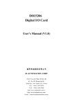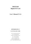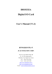
1
EMC8485 Ethernet to RS422/485 converter module User's Manual (V1.2) 健昇科技股份有限公司 JS AUTOMATION CORP. 新北市汐止區中興路 100 號 6 樓 6F., No.100, Zhongxing Rd., Xizhi Dist., New Taipei City, Taiwan TEL:+886-2-2647-6936 FAX:+886-2-2647-6940 http://www.automation.com.tw http://www.automation-js.com/ E-mail:[email protected] Correction record Version Record 1.0 firmware version 1.0 up 1.1 Add System Reset 1.2 1. Modify 3.5.5 dimension 2. Add 4.2 dimension Image 1 Contents 1. Forward ................................................................................................................................................ 4 2. 3. Features ................................................................................................................................................ 5 Specifications ....................................................................................................................................... 6 3.1 RS422/485 ................................................................................................................................... 6 3.2 Digital input................................................................................................................................. 6 3.3 Digital output............................................................................................................................... 6 3.4 Ethernet ....................................................................................................................................... 6 3.5 General ........................................................................................................................................ 6 Layout and dimensions ........................................................................................................................ 7 4.1 EMC8485 Layout ........................................................................................................................ 7 4.2 EMC8485 Dimension.................................................................................................................. 7 4. 5. Pin definitions ...................................................................................................................................... 8 8. 5.1 JM2 pin definitions...................................................................................................................... 8 5.2 JM3 pin definitions(EMC8485) .................................................................................................. 8 I/O Interface diagram ........................................................................................................................... 9 6.1 I/O diagram ................................................................................................................................. 9 System Reset ...................................................................................................................................... 10 7.1 Normal system reset .................................................................................................................. 10 7.2 Reset to default .......................................................................................................................... 10 Applications ....................................................................................................................................... 11 9. Ordering information ......................................................................................................................... 12 6. 7. 2 Notes on hardware installation Please register as user’s club member to download the “Step_by_step_installation_of_Ethernet_module” document from http://automation.com.tw 3 1. Forward Thank you for your selection of Ethernet module EMC8485 ethernet to isolated RS422/485 converter module. Thanks to the booming of network, Ethernet become a reliable and low cost solution for data communication. To utilize the Ethernet as data communication highway of industrial control devices is more attractive than ever. EMC8485 module is a converter module, which can convert the traditional RS422/485 communication protocol to Ethernet or vice versa. With the extra 8-bit I/O and counter function, you can extend the convert to some control functions. A stable, high reliability and remote addressable module give you a new approach of application. In the same series: EMC8432 Ethernet to RS232 converter with 8-bit I/O Any comment is welcome, please visit our website http://www.automation.com.tw/ http://www.automation-js.com/ for the up to date information. 4 2. Features - Over-voltage protection on digital input - Various IO combinations : 8 bit configurable I/O’s, any bit can be input or output - High drive capacity on digital output - Digital I/P as counter input - Baudrate up to 921.6K - Wide power range - RS422, RS485 software selectable - IP re-assignment - 10/100M auto detection - Software key function 5 3. Specifications 3.1 RS422/485 3.1.1 Isolation : magnetic coupler 3.1.2 Baud rate: 1200, 2400, 4800, 9600, 19200, 38400, 57600, 115200, 921600 3.1.3 Data bits: 5, 6, 7, 8 3.1.4 Stop bits: 1, 1.5, 3.1.5 Parity: None, Even, Odd 3.2 Digital input 3.2.1 Input points: max 8 (Configurable) 3.2.2 3.2.3 3.2.4 3.2.5 Logic high level: 3.15V(min) Logic low level: 1.35V(max) Over-voltage protection: 60Vdc(max) Over-current protection: 50mA(max) 3.3 Digital output 3.3.1 Transistor output: max 8 (Configurable) 3.3.2 Transistor capacity: 50mA, 45Vdc(max) 3.4 Ethernet 3.4.1 10/100M auto switch x 2 port 3.5 General 3.5.1 Power requirement: 12Vdc ~24Vdc 3.5.2 Operation Temperature: 0 ~ +70 degree C 3.5.3 Storage Temperature: -20 ~ +80 degree C 3.5.4 Operation Humidity: 5~95% RH, non-condensing 3.5.5 Dimension: 115.4(D)*136(W)*34(H) mm 4.6(D)*5.4(W)*1.4(H) in 6 4. Layout and dimensions 4.1 EMC8485 Layout LED1: system active LED J2,J3: Ethernet RJ45 socket JM2: I/O connector JM3: RS422/485 connector JM4: external power 24V connector SW2: system reset switch 4.2 EMC8485 Dimension 7 5. Pin definitions 5.1 JM2 pin definitions +Ve* 1 IO_0 2 IO_1 3 IO_2 4 IO_3 5 IO_4 6 IO_5 7 IO_6 8 IO_7 9 GND 10 5.2 JM3 pin definitions(EMC8485) RS422 RS485 TXD+ 1 1 TXD- 2 2 RXD+ 3 3 D+ RXD- 4 4 D- EXTG 5 5 EXTG Note: Always connect the EXTG between the communication devices for RS422 or RS485, do not let the signal floating to improve noise immunity. * +Ve can floating or voltage input (voltage range +3.3V ~ +24V) * +Ve can apply different voltage as you need. 8 6. I/O Interface diagram 6.1 I/O diagram Note: If +Ve is externally applied +24V then the IO_0 ~ IO_7 will be also applied. 9 7. System Reset The system reset switch SW2 has provide normal system reset and reset to default functions. 7.1 Normal system reset Push the SW2 for more than 5 seconds, the power LED will flick at 3 HZ to signal the system has already reset. Once you release the switch, the LED will return to normal flick rate. 7.2 Reset to default Push the switch while power on (We suggest to push the switch first then power on and wait for 3 seconds) for 3 seconds, the LED will: 1. stop flick 2. flicking at 3 Hz--- system now setting default data 3. flicking at normal speed --- system now already reset, you can release the switch. item default value IP 192.168.0.100 password 12345678 socket port 6936 IO_config ALL input (0xFF) polarity ALL inactive (0x0) WDT timer 1second(0xA) WDT output state ALL inactive (0x0) Standalone function ALL clean (0x0) Power on standalone Disable (0x0) 10 8. Applications RS422/485 to ethernet converter Ethernet to RS422/485 converter Remote signal input Remote signal counter Remote signal output 11 9. Ordering information PRODUCT DESCRIPTIONS EMC8485 Ethernet module to RS422/485 (8 IO) Module JD52000 110/220Vac to 24Vdc @1.5A power supply JD52026 110/220Vac to 24Vdc @0.75A power adapter 12