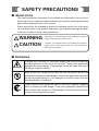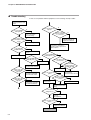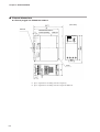
1
No. CP-SP-1214E
FRS110
Multiburner Control
FSG Relay
User's Manual
Thank you for purchasing the FRS110
Multiburner Control FSG Relay.
This manual contains information for
ensuring the correct use of the FRS110.
It also provides necessary information
for installation, maintenance, and troubleshooting.
This manual should be read by those
who design and maintain equipment
that uses the FRS110. Be sure to keep
this manual nearby for handy reference.
RESTRICTIONS ON USE
This product has been designed, developed and manufactured for general-purpose
application in machinery and equipment.
Accordingly, when used in applications outlined below, special care should be taken to
implement a fail-safe and/or redundant design concept as well as a periodic
maintenance program.
• Safety devices for plant worker protection
• Start/stop control devices for transportation and material handling machines
• Aeronautical/aerospace machines
• Control devices for nuclear reactors
Never use this product in applications where human safety may be put at risk.
NOTICE
Be sure that the user receives this manual before the product is used.
Copying or duplicating this user’s manual in part or in whole is forbidden. The information and specifications in this manual are subject to
change without notice.
Considerable effort has been made to ensure that this manual is free
from inaccuracies and omissions. If you should find an error or omission, please contact Yamatake Corporation.
In no event is Yamatake Corporation liable to anyone for any indirect,
special or consequential damages as a result of using this product.
©2006 Yamatake Corporation ALL RIGHTS RESERVED
SAFETY PRECAUTIONS
■ About Icons
The safety precautions described in this manual are indicated by various icons.
Please be sure you read and understand the icons and their meanings described
below before reading the rest of the manual.
Safety precautions are intended to ensure the safe and correct use of this product, to prevent injury to the operator and others, and to prevent damage to property. Be sure to observe these safety precautions.
WARNING
CAUTION
Warnings are indicated when mishandling this product
might result in death or serious injury.
Cautions are indicated when mishandling this product
might result in minor injury to the user, or only physical
damage to the product.
■ Examples
Triangles warn the user of a possible danger that may be caused by
wrongful operation or misuse of this product. These icons graphically
represent the actual danger. (The example on the left warns the user of
the danger of electric shock.)
White circles with a diagonal bar notify the user that specific actions are
prohibited to prevent possible danger. These icons graphically represent
the actual prohibited action. (The example on the left notifies the user
that disassembly is prohibited.)
Filled-in black circles instruct the user to carry out a specific obligatory
action to prevent possible danger. These icons graphically represent the
actual action to be carried out. (The example on the left instructs the user
to remove the plug from the outlet.)
i
WARNING
Before removing, mounting or wiring the FRS110, be sure to turn the
power OFF. Failure to do so might cause electric shock.
Do not touch the terminals on the FSG relay. Doing so might result in
an electric shock.
This FSG relay is for batch operation (at least one start and stop in 24
hours of operation) needing a safe start feature.
When using this product for continuous operation (continuous
combustion for 24 hours or longer), combine it with the R4332A or
R4332B which have a self-checking function.
This FSG relay does not have the prepurge timing functions necessary
for burner ignition. Take timer functions into consideration when
designing your control system.
Do not connect the solenoid valve to the voltage side.
If a ground fault occurs, ground current will flow to the solenoid valve
and open it, causing fuel to flow regardless of the state of this relay.
Make sure that the pilot and main burner ignition times do not exceed
the burner ignition time which the equipment manufacturer specifies.
Excessively long ignition time might cause fuel to accumulate in the
combustion chamber and an explosive air-fuel mix to form, resulting in
the risk of a serious explosion.
Before carrying out the pilot turndown test or ignition spark response
test, be sure that all manual fuel valves are closed.
Do not operate the FSG relay without completing the tests described
in Chapter 4 and the tests specified by the equipment manufacturer.
If the flame detector is set so that it detects a pilot flame that is too
small to ignite the main burner, flame failure in the main burner will not
be detectable. In this case, fuel would continue to be supplied,
causing a serious explosion hazard. Be sure to carry out the pilot
turndown test carefully.
If the pilot turndown test must be carried out repeatedly, completely
shut down all equipment each time the test is finished, and completely
discharge unburned gas or fuel that has accumulated in the smoke
ducts and combustion chamber. Failure to discharge unburned gas or
fuel may result in an explosion.
After the pilot turndown test is completed, turn the power OFF. Be sure
to restore all test jumper leads, limit switches and control settings used
in the test to their original settings.
ii
WARNING
Connect the power source last to prevent electric shock or damage.
If the power line accidentally touches the wrong terminal, electric
shock or damage might result.
Connect the load (ignition transformer, solenoid valve, etc.) to the
output terminals directly. If it is not directly connected, combustion
safety cannot be ensured.
Do not extend the lead wires of the reset input for more than the
allowable wiring length of 10 meters. Never input a reset command
from a remote location where burner status cannot be checked.
If the FRS110 locks the burner out, be sure to remove the cause before
resetting. Do not repeatedly enter the reset input. Doing so could
cause an explosion.
Make sure that the ultraviolet flame detector cannot detect UV rays
emitted by sources other than the burner. If the ultraviolet flame
detector responds to other UV sources, it will report that there is a flame
even if the burner flame is out. As a result, fuel will continue to be
supplied, causing a very serious explosion hazard.
CAUTION
The FRS110 has extremely important functions for safe operation of
equipment. Follow the instructions in the user’s manual to ensure safe
use.
Do not transport the FSG relay while it is mounted on a DIN rail. Before
transporting, remove it from the subbase and pack it in its original
packing case. If it is transported on a DIN rail, it might fall off and be
damaged.
Mounting, wiring, maintenance, inspection and adjustment should be
carried out by a specialist who has been trained in how to handle
burners and combustion safeguard equipment.
Do not mount the FSG relay in the following locations:
• Near corrosive chemicals or gases (ammonia, sulfur, chlorine,
ethylene compounds, acid, etc.)
• Where subject to water spray or extreme humidity
• Where subject to high temperatures
• Where subject to continuous vibration for a long time
After wiring, be sure to check the wiring connections. Operating this
device with wires wrongly connected might cause damage or
malfunction.
iii
CAUTION
Make sure that the loads connected to the terminals do not exceed the
specified ratings.
Make sure that power of the same voltage and frequency as indicated
on the model number label is supplied to the FSG relay.
When configuring control circuits, select reliable timers and auxiliary
relays as necessary for additional functions.
Be sure to ground this device using a lead with a resistance of less
than 100Ω, and be sure to ground the burner body.
Keep power lines and ignition transformer high-voltage cables separate
from the flame detector wires.
Run the ignition transformer high-voltage cable separately and keep it
at least 10cm away from the FSG relay.
When equipment is restarted after a safety shutoff, check all items
described in Chapter 4, TRIAL-RUN ADJUSTMENT.
Before maintenance and inspection of the burner, be sure to do the
pilot turndown test. Carry out this test at least once every year.
When cleaning the burner, clean the flame detector also.
When mounting or wiring, be sure to follow the instructions in this
user’s manual and manuals provided by the equipment manufacturer
or other device manufacturers.
Follow all applicable regulations when wiring.
Make sure that ignition transformer high-voltage cables are properly
connected to prevent contact failure. Poor contact might generate
high-frequency radio waves, resulting in noise in radios or other
electrical appliances, or causing malfunction. Also, connect the
ignition transformer ground lead directly to the burner body, or to a
metal part that is electrically connected to the burner body.
iv
Conventions Used in This Manual
The following conventions are used in this manual:
Handling Precautions:
Handling Precautions indicate items that the user should pay attention to
when handling the FRS110.
Note:
(1), (2), (3):
Notes indicate information that might benefit the user.
Numbers within parentheses indicate steps in a sequence or parts of an
explanation.
v
Contents
SAFETY PRECAUTIONS
Conventions Used in This Manual
Chapter 1.
OVERVIEW
■
■
■
■
■
Chapter 2.
Overview.......................................................................................................1-1
Features........................................................................................................1-1
Names and functions ..................................................................................1-2
Recommended flame relays and flame sensors.......................................1-2
FSG system configuration ..........................................................................1-3
MOUNTING AND WIRING
2.1 Mounting and Wiring the Subbase...................................................................2-1
2.2 Wiring..................................................................................................................2-3
■ Wiring diagrams (FSG relay and flame relay) ...........................................2-4
■ Wiring the power supply and the solenoid valve .....................................2-4
■ Wiring the surge absorber ..........................................................................2-7
Chapter 3.
OPERATION
■ Sequence diagrams.....................................................................................3-1
■ Operation details .........................................................................................3-3
Chapter 4.
TRIAL-RUN ADJUSTMENT
■
■
■
■
■
Chapter 5.
Overview.......................................................................................................4-1
How to measure the flame signal...............................................................4-2
Pilot turndown test ......................................................................................4-3
Ignition spark response test.......................................................................4-5
Safety shutoff test .......................................................................................4-6
MAINTENANCE AND INSPECTION
■ Inspection cycle...........................................................................................5-1
■ Troubleshooting ..........................................................................................5-2
Chapter 6.
SPECIFICATIONS
■ Specifications ..............................................................................................6-1
■ External dimensions....................................................................................6-2
vi
Chapter 1.
OVERVIEW
■ Overview
The FRS110 multiburner control FSG relay (hereafter referred to as the FSG relay
or the FRS110) is equipped with a burner ignition control function. When used in
combination with the FRS100 flame relay functioning as a flame detector, the FSG
relay is suitable for use in batch-operation (intermittent) combustion equipment.
At startup, if there is any problem with the FRS110 or with the flame relay, burner
ignition is prevented.The FRS110 has both a safe start function and a combustion
safety shutoff function that closes the gas shutoff valve if a flame failure signal is
received from the FRS100 during operation.
A multiburner combustion safety control can easily be made by combining one
FRS110 with multiple flame relays.
Note that the FRS110 does not provide a prepurge timer function.
■ Features
• The FRS110 can control synchronous multiburner ignition and shutdown when
combined with multiple flame relays.
• Upon startup, the FRS110's start check function is activated. If anything is
abnormal, the FRS110 ensures safety by stopping the ignition process. Also, if
there is an ignition failure or flame failure, the FRS110 maintains safety by
initiating burner lockout. The FRS110's safe design ensures that the burner
cannot be started until an external reset signal is received.
• When lockout occurs, an alarm output signal is sent via the alarm contacts.
• Because of its compact design, the FRS110 can be plugged into a wiring
subbase, which can be mounted by screws or on a DIN rail.
• LED indicators allow an easy status check of power, start signal input, alarm
situation, ignition transformer, pilot valve, and main valve.
1-1
Chapter 1. OVERVIEW
■ Names and functions
● FRS110
LED indicators
POWER (green):
Power ON/OFF
START (green):
Start contact
ON/OFF
ALARM (red):
Alarm ON/OFF
FRS50A100 subbase (sold separately)
DIN rail
IG (red):
Ignition transformer
ON/OFF
PV (red):
Intermittent pilot valve
ON/OFF
MV (red):
Main valve ON/OFF
Cover removed
Body mounting screw
Dedicated connector for
optional flame voltage meter
(sold separately)
Cover
DIN rail
locking tab
M3.5
terminal
screws
Terminals for reset switch
Terminals for alarm output
● FRS50A100 subbase (sold separately)
■ Recommended flame relays and flame sensors
● Flame relay and flame detector
Flame relay
FRS100B
FRS100C
Flame detector
Ultraviolet Flame Detector
Flame Rod
Minipeeper Ultraviolet Flame Detector
● Optional parts (sold separately)
Name
1-2
Model No.
Subbase
FRS50A100
Lightning surge absorber
83968019-001
C7012A/C
C7007A, C7008A
C7027A, C7035A
Chapter 1. OVERVIEW
■ FSG system configuration
The FRS110 provides ignition control, while the FRS100 flame relay detects the
flame. To construct a multiburner system, take the following items into
consideration:
• Burner ignition and shutdown sequences
• Method of safety shutdown in the event of flame failure
● Synchronous ignition and shutdown (two-burner case)
Only one main valve and one pilot valve are needed for two burners. (For extra
safety, redundant valves may be used, as shown in the diagram,)
FSG Flame Flame
relay relay relay
Flame detector
Ignition transformer
Gas
Main valve
Ignition process:
•The FRS110 ignites all pilot burners
simultaneously, and then detects the
pilot flame.
•After the pilot flame confirmation
period, the FRS110 opens the main
valve and ignites the main burner.
Pilot valve
● Asynchronous ignition and shutdown (two-burner case)
One main valve and one pilot valve are needed for each burner. (For extra
safety, redundant valves may be used, as shown in the diagram,)
FSG Flame
relay relay
Flame detector
Gas
Main valve
Ignition transformer
Pilot valve
Pilot valve
Ignition transformer
Main valve
Ignition process:
The FRS110 ignites and shuts off
each burner individually.
Flame detector
FSG
relay
Flame
relay
1-3
Chapter 2.
2.1
MOUNTING AND WIRING
Mounting and Wiring the Subbase
CAUTION
Do not mount this control in the following locations:
• Where subject to corrosive chemicals or gases (such as ammonia, sulfur,
chlorine, ethylene compounds, acid.)
• Where subject to water spray or extreme humidity
• Where subject to high temperatures
• Where subject to continuous vibration
Do not transport the FSG relay while it is mounted on a DIN rail. Before
transporting, remove it from the subbase and pack it in its original packing
case. If it is transported on a DIN rail, it might fall off and be damaged.
When mounting or wiring, be sure to follow the instructions in this user’s
manual and manuals provided by the equipment manufacturer or other
device manufacturers.
● Mounting location
As shown below, keep a enough space around the control for heat radiation, and to
facilitate mounting, removal, wiring and maintenance.
Above: 50mm min.
PRS 100
FSG RELAY
POWER
IG
START
PV
ALARM
MV
PRS 100
FSG RELAY
POWER
IG
START
PV
ALARM
MV
20mm min.
PRS 100 FLAM
E RELAY
•
•
•
POWER
IG
START
PV
ALARM
MV
20mm min.
Below: 20mm min.
Handling Precautions
• If there is room, leave as much space as possible between the FRS and
other FRS units to allow for heat radiation.
• If ambient temperature is close to the allowable upper limit, reduce the
internal temperature of the control panel by mounting a panel cooler or a
cooling fan.
Allowable ambient temperature upper limits:
• Gang-mounting: 45°C
• Stand-alone mounting: 60°C
2-1
Chapter 2. MOUNTING AND WIRING
● Mounting direction
• Mount so that the arrow on the subbase is facing upwards.
• Mount so that the display panel is in front.
PRS 100
POWER
FSG RELAY
IG
START
PV
ALARM
MV
● Mounting on a DIN rail
(1) Slide the DIN rail locking tab downwards.
(2) Place the subbase on the DIN rail, with the arrow on the subbase facing
upwards.
(3) Slide the DIN rail locking tab to secure the subbase to the DIN rail.
(4) Wire the subbase terminals as instructed in section 2.2, Wiring.
(5) Pull the bottom of the cover forward to remove.
(6) Insert the FRS110 into the subbase with the display panel in front.
(7) Tighten the mounting screw in the center of the FRS110 attach it to the
subbase, using a maximum torque of 0.3N•m.
(8) Wire the alarm output signal and reset signal.
(9) Reattach the cover.
32
UP
M4
(2 locations)
● Mounting on panel directly
(1) Drill two M4 mounting holes in the panel so that the arrow
on the subbase will be facing upward.
(2) Attach the subbase to the panel using two M4 screws at a maximum torque of
0.7N•m.
Handling Precaution
• Do not tighten the subbase mounting screws with a torque exceeding
the maximum.
(3) Wire the subbase terminals as instructed in section 2.2, Wiring.
(4) Pull the bottom of the cover forward to remove.
(5) Insert the FRS110 into the subbase with the display part upwards.
(6) Tighten the mounting screw in the center of the FRS110 to attach it to the
subbase, using with a maximum torque of 0.3N•m.
(7) Wire the alarm output signal and reset signal.
(8) Reattach the cover.
2-2
Chapter 2. MOUNTING AND WIRING
2.2 Wiring
WARNING
Connect the power source last to prevent electric shock or damage.
If the power line accidentally touches the wrong terminal, electric shock or
damage might result.
Connect the load (ignition transformer, solenoid valve, etc.) to the output
terminals directly. If it is not directly connected, combustion safety cannot be
ensured.
CAUTION
When mounting or wiring, be sure to follow the instructions in this user’s
manual and manuals provided by the equipment manufacturer or other
device manufacturers.
Follow all applicable regulations when wiring.
Make sure that the loads connected to the terminals do not exceed the
ratings indicated in the specifications.
Make sure that power of the same voltage and frequency as indicated on the
Model No. label is supplied to the FSG relay.
When configuring control circuits, select reliable timers and auxiliary relays
as necessary for additional functions.
Be sure to ground this control using a lead with a resistance of less than
100Ω, and be sure to ground the burner body.
Keep power lines and ignition transformer high-voltage cables separate from
the flame detector wires.
Run the ignition transformer high-voltage cable separately and keep it at
least 10cm away from the FSG relay.
Make sure that ignition transformer high-voltage cables are properly
connected to prevent contact failure. Poor contact might generate highfrequency radio waves, resulting in noise in radios or other electrical
appliances, or causing malfunction. Also, connect the ignition transformer
ground lead directly to the burner body, or to a metal part that is electrically
connected to the burner body.
After wiring, be sure to check the wiring connections. Operating this device
with wires wrongly connected might cause damage or malfunction.
In setting the timer, follow the Japan Gas Association's Safety Engineering
Directives for Industrial Gas Combustion Equipment or similar guidelines.
Do not extend the lead wires of the reset input for more than the allowable
wiring length of 10 meters. Never input a reset command from a remote
location where burner status cannot be checked.
2-3
Chapter 2. MOUNTING AND WIRING
■ Wiring diagrams
● FRS110 with one flame relay (FRS100)
Power supply
(H)
Power supply
(G)
Start switch
Limit
FRS110
1
5
2
Power circuit
K1
8
K2
Input circuit
3
Pilot valve
6
Ignition transformer 1
4
Ignition circuit
K1
K2
K2
K3
Alarm circuit
K3
Reset input
B
A
C
7
Main valve
Reset
switch 1
D
Alarm 1
FRS100
1
7 Input circuit
Start check
circuit
2K
8
3
2
Power circuit
2K
4
Combustion lamp 1
1K
Flame amplifying
circuit
2K
5
6
Flame detector
Handling Precautions
• The power supply is marked H and G for the voltage and ground sides,
respectively. Connect the voltage side (H) to terminal 1 and the ground
side (G) to terminal 2.
• Install the ignition transformer directly on the burner itself or on a metallic
part electrically connected to the burner.
• Use 2mm2 wire with indoor PVC insulation at each terminal.
• Use indoor PVC-insulated wire at least 0.75mm2 (30 strands 0.18mm in
dia.) for power connections.
2-4
Chapter 2. MOUNTING AND WIRING
● FRS110 with two flame relays (FRS100)
Power supply
(H)
Start switch
Power supply
(G)
CR2
CR3
CR4
CR8 Stop switch
CR5
CR1
Start
CR1
Reset switch 1
TM2
C D
CR1
Limit
CR6
1
5
CR7
CR2
FRS110
2
K1
CR3
3
8
K2 6
4
K2
7
A B
CR4
CR5
Pilot
confirmation timer
TM1
TM1
Main valve
TM2
Main Ignition timer
CR8
Alarm 1
1
FRS100
7
2
1K
2K
8
3
4
Combustion lamp 1
5 6
CR6
Flame detector 1
1
FRS100
7
2
1K
2K
8
3
4
Combustion lamp 2
5 6
CR7
Flame detector 2
CR2
Pilot valve 1
CR3
Pilot valve 2
CR2
CR3
CR4
Ignition transformer 1
CR4
CR5
Ignition transformer 2
CR5
Handling Precautions
• The power supply is marked H and G for the voltage and ground sides,
respectively. Connect the voltage side (H) to terminal 1 and the ground
side (G) to terminal 2.
• Install the ignition transformer directly on the burner itself or on a metallic
part electrically connected to the burner.
• Use 2mm2 wire with indoor PVC insulation at each terminal.
• Use indoor PVC-insulated wire at least 0.75mm2 (30 strands 0.18mm in
dia.) for power connections.
2-5
Chapter 2. MOUNTING AND WIRING
■ Wiring of power supply and solenoid valve
CAUTION
Do not connect the solenoid valve to the voltage side.
If a ground fault occurs, ground current will flow to the solenoid valve and
open it, causing fuel to flow regardless of the state of this relay.
FRS110
FSG relay
Burner
Power supply
Ground side (G)
N
(Ground fault)
L
Combustion unit
Voltage side (H)
Valve (closed)
Fuel
● Correct wiring
When wiring is done correctly as shown in the above figure, ground fault current
cannot flow to the solenoid valve, even if the fault was caused by an insulation
failure on the voltage side (H). Therefore the valve does not open and there is no
danger of fuel discharge.
(Ground fault)
FRS110
FSG relay
Burner
Power supply
Ground side (G)
N
L
Combustion unit
Voltage side (H)
Valve (open)
Fuel
● Incorrect wiring
If the valve is connected to the voltage side as illustrated above, ground fault
current will flow to the solenoid valve and open it, discharging fuel.
2-6
Chapter 2. MOUNTING AND WIRING
■ Wiring the surge absorber
Wire as shown below when using a surge absorber (model No. 83968019-001,
ordered separately) for protection from lightning surge.
Handling Precautions
• Use at least JIS C 3306, 0.75mm2 power leads (30 strands 0.18mm in
dia.) for wiring to the power supply.
• Attach a Faston receptacle (AMP #187) to one end of the power leads,
and make the wires as short as possible.
• Ground the surge absorber mounting bracket by attaching to a grounded
metal part such as the burner body.
2-7
Chapter 3.
OPERATION
■ Sequence diagrams
Power supply
(H)
Power supply
(G)
Start switch
Limit
FRS110
1
5
2
Power circuit
K1
8
K2
Input circuit
3
Pilot valve
6
Ignition transformer 1
4
Ignition circuit
K1
K2
K2
K3
Alarm circuit
K3
Reset input
B
A
C
7
Main valve
Reset
switch 1
D
Alarm 1
FRS100
1
7 Input circuit
Start check
circuit
2K
8
3
2
Power circuit
2K
4
Combustion lamp 1
1K
Flame amplifying
circuit
2K
5
6
Flame detector
• Normal operation
[Input]
Start input
Flame signal input
Term. 8
Term. 4
[Output]
Ignition transformer
Intermittent pilot valve
Main valve
Alarm output
Term. 6
Term. 3
Term. 7
Term. A-B
[Indicators]
POWER
START
IG
PV
MV
AL
Safety Time
Standby
RUN
Standby
Start Check Time
3-1
Chapter 3. OPERATION
• Ignition failure
[Input]
Start input
Flame signal input
Term. 8
Term. 4
[Output]
Ignition transformer
Intermittent pilot valve
Main valve
Alarm output
Term. 6
Term. 3
Term. 7
Term. A-B
[Indicators]
POWER
START
IG
PV
MV
AL
Safety Time
Standby
Alarm
Start Check Time
• Flame failure
[Input]
Start input
Flame signal input
Term. 8
Term. 4
[Output]
Ignition transformer
Intermittent pilot valve
Main valve
Alarm output
Term. 6
Term. 3
Term. 7
Term. A-B
[Indicators]
POWER
START
IG
PV
MV
AL
RUN
Note:
Alarm
. The Flame Failure Response Time, the time from flame failure to
flame signal shutoff, is dependent upon the FRS100 flame
relay specifications.
. Safety Time means pilot flame-establishing period.
3-2
Chapter 3. OPERATION
■ Operation details
• Normal operation
Input conditions
FRS110 operation
System status
Start contact
(terminal 8): ON
•Ignition transformer
starts operating.
•Intermittent pilot valve
Relay K1 remains ON during the Safety Time (ignition
opens.
trial time).
Flame signal input
(terminal 4): ON
If terminal 4 receives flame signal input by the end of •Intermittent pilot valve
the Safety Time (ignition trial time), relay K1 remains
opens.
ON, relay K2 is energized, and the regular combustion •Main valve opens.
run begins.
•Ignition transformer
stops.
Start contact
(terminal 8): OFF
If the power to terminal 8 is turned OFF, relays K1
and K2 are turned OFF.
After power reaches terminal 8, and after the start
check time has elapsed, relay K1 is turned ON.
•Ignition transformer
stops.
•Main valve closes.
• Ignition failure operation
Input conditions
FRS110 operation
System status
Start contact
(terminal 8): ON
After power reaches terminal 8, and after the start
check time has elapsed, relay K1 is turned ON.
•Ignition transformer
starts operating.
•Intermittent pilot valve
Relay K1 remains ON during the Safety Time (ignition
opens.
trial time).
Flame signal input
(terminal 4): OFF
If there is no flame signal input to terminal 4 by the
•Ignition transformer
end of the Safety Time (ignition trial time), relay K1
stops.
turns OFF and an alarm signal (terminals A-B) is output. •Intermittent pilot valve
closes.
•Alarm output.
• Flame failure operation
Input conditions
FRS110 operation
System status
Flame signal input
(terminal 4): OFF
If flame failure occurs during the regular combustion
run, the flame signal turns OFF, relays K1 and K2
turn OFF, and an alarm signal is output to terminals
A and B.
•Intermittent pilot valve
closes.
•Main valve closes.
•Alarm output.
• False flame operation
Input conditions
Flame signal input
(terminal 4): ON
Start contact
(terminal 8): ON
FRS110 operation
System status
If, when power is supplied to terminal 8, a flame signal
has already been input to terminal 4, the FRS110
does not begin the ignition trial, but waits until the flame
signal stops.
3-3
Chapter 4. TRIAL-RUN ADJUSTMENT
WARNING
Make sure that the pilot and main burner ignition times do not exceed the
bur ner ignition time which the equipment manufacturer specifies.
Excessively long ignition time might cause fuel to accumulate in the
combustion chamber and an explosive air-fuel mix to form, resulting in the
risk of a serious explosion.
Do not touch the terminals during trial operation adjustments. Doing so might
result in an electric shock.
Before removing, mounting or wiring the FRS110, be sure to turn the power
OFF. Failure to do so might cause electric shock.
Before carrying out the pilot turndown test or ignition spark response test, be
sure that all manual fuel valves are closed.
Do not operate this control without completing the tests described in this
chapter and the tests of specified by the equipment manufacturer.
If the FRS110 locks the burner out, be sure to remove the cause before
resetting. Do not repeatedly enter the reset input. Doing so could cause an
explosion.
■ Overview of adjustments
The following table shows the items described in this chapter.
Item
Applicable FSG systems
Flame signal measurement
All
Pilot turndown test
Systems using a pilot burner
Ignition spark response test
Systems using an ultraviolet flame detector
Safety shutdown test
All
Handling Precautions
• After completing the above, make sure that all of the adjustment
requirements are satisfied. All of the adjustment requirements must be
satisfied by the final mounting position of the flame detector.
● Required items
• Tester (input impedance of 100kΩ or more)
Range: 0 to 300Vac, 0 to 5Vdc
• Two jumper leads with crocodile clips, AWG14 (2mm2) or more, approximately
30cm long.
• Insulation tester: 500Vdc megger
● Preliminary inspection
• Check all wiring.
• Make sure that the controller is mounted at a location within the permissible
ambient temperature.
• Make sure that the flame detector is properly mounted. (For details, see the
flame detector user’s manual.)
4-1
Chapter 4. TRIAL-RUN ADJUSTMENT
• Disconnect the loads and flame detector wiring. Measure the insulation
resistance between the terminals and panel ground, and make sure that the
resistance is 50MΩ or more using an insulation tester or megger of 500Vdc or
more.
• Valves and cocks on each of the fuel lines must be closed, and the fuel
chamber must be thoroughly purged.
■ How to measure the flame signal
(1) Start the equipment and measure the flame voltage for each burner under
various conditions (at startup, normal operation, etc.).
(2) When measuring the flame voltage, insert the tester probes into the holes for
terminals A and B at the bottom front of the flame relay as shown below.
FRS100 FLAME RELAY
POWER
FLAME
Terminal A
Terminal B
Tester
Input impedance of 100kΩ or more
Black
Red
+
–
0 to 5Vdc range
(3) Refer to the following table for voltage:
Flame detector
Recommended
Checklist
flame voltage
Minipeeper Ultraviolet 2Vdc min.
• Make sure that the flame is correctly
Flame Detector
monitored.
(C7027A or C7035A)
• The front of the flame detector must be
free of dirt.
• The monitoring tube must not be blocked
with soot.
(4) If the flame signal fluctuates, check the flame detector mounting position and
wiring again.
4-2
Chapter 4. TRIAL-RUN ADJUSTMENT
■ Pilot turndown test
This test is for checking that even if gas pressure and air pressure are at their
worst, any pilot flame that can be detected by the flame detector will reliably
ignite the main burner.
WARNING
If the flame detector is set so that it detects a pilot flame that is too small to
ignite the main burner, flame failure in the main burner will not be detectable.
In this case, fuel would continue to be supplied, causing a serious explosion
hazard. Be sure to carry out the pilot turndown test carefully.
If the pilot turndown test must be carried out repeatedly, completely shut
down all equipment each time the test is finished, and completely discharge
unburned gas or fuel that has accumulated in the smoke ducts and
combustion chamber. Failure to discharge unburned gas or fuel may result in
an explosion.
After the pilot turndown test is completed, turn the power OFF. Be sure to
restore all test jumper leads, limit switches and control settings used in the test
to their original settings. If this control is operated without restoring the
original settings, equipment damage, gas leak, or explosion might result.
CAUTION
Only an experienced specialist who has knowledge and technical skills
related to combustion equipment and combustion safety shoud carry out the
pilot turndown test.
Handling Precautions
• If fuel pressure limit switches are open (in use) during this test, connect
jumpers to set the limit switches ON.
● Procedure
(1) Turn the power switch OFF.
(2) Close the manual valve for the pilot and for the main burner to stop the gas
flow.
(3) Open the pilot manual valve.
(4) Turn the power switch ON, and then turn the start switch on. The pilot will
ignite.
(5) Close the pilot manual valve slowly. The pilot flame will gradually grow
smaller. Continue to close the manual valve until the flame detector can no
longer detect the flame. At this point flame relays 1K and 2K turn OFF and
lock out. Record the pressure just before the 2K flame relay turns off.
4-3
Chapter 4. TRIAL-RUN ADJUSTMENT
(6) Then open the pilot manual valve slowly until the pressure matches the
pressure just before the 2K flame relay turned off.
(7) Reset the FSG relay, and restart the equipment, and then press the ignition
switch again to ignite the pilot.
(8) Make sure that the main burner ignites smoothly in one second or less when
the main manual valve is opened.
(9) Change the gas pressure from minimum to maximum, and ignite the main
burner 5-6 times. Make sure that the main burner ignites smoothly every time.
(10) If the main burner does not ignite, the reason is probably that the pilot flame
is too small. Make the pilot flame larger and carry out the following
adjustment:
• Either move the flame detector's line of sight slightly away from the axis
of the pilot flame, or put in a diaphragm to correct the flame size. (Set the
flame size so that the main burnert ignites without fail at the minimum
flame voltage.)
(11) After adjusting, repeat steps (5) to (8), and make sure that main burner ignites
without fail.
(12) After this test is completed, return the main manual valve to its fully open
position. Then, make sure that the flame signal is appropriate.
(13) Take off any jumper leads connected to limit switches during this test to
restore them to their original condition.
4-4
Chapter 4. TRIAL-RUN ADJUSTMENT
■ Ignition spark response test
This test should be carried out on any equipment that uses an ultraviolet flame
detector. The test is to check that the ultraviolet flame detector does not respond to
UV rays emitted from the ignition spark.
● Ultraviolet Flame Detector
CAUTION
Make sure that the ultraviolet flame detector cannot detect UV rays emitted
by sources other than the burner. If the ultraviolet flame detector responds to
other UV sources, it will report that there is a flame even if the burner flame is
out. As a result, fuel will continue to be supplied, causing a very serious
explosion hazard.
Carry out the following test to check that the ultraviolet flame detector does not
respond to the UV rays emitted from the ignition spark.
(1) Close the pilot manual valve and the main burner manual valve.
(2) Begin operation and measure the flame voltage during the pilot ignition
sequence to check for any influence from UV rays.
(3) If the FLAME LED of the flame relay lights up, make one of the following
adjustments, referring also to the equipment user’s manual.
• Move the ultraviolet flame detector or ignition spark rod so that it is not
affected.
• Install a shield, for example, to prevent UV rays from the spark from
entering the optical path of the ultraviolet flame detector, and adjust so that
the influence of the spark on the flame voltage is 0.4Vdc or less.
4-5
Chapter 4. TRIAL-RUN ADJUSTMENT
● Cautions regarding UV sources other than flames
The table below shows sources other than flames that emit UV rays that can be
detected by the flame detector. Make sure that these UV sources do not influence
operation of the ultraviolet flame detector under any operating conditions.
UV relay sources
1260°C or higher red-hot chamber wall
Sparks (ignition transformer, welding arc, lightning)
Gas laser
Sunlamp
Sterilizing lamp
Strong flashlight (in direction of UV photoelectric tube)
All other UV sources
Gamma ray and X-ray sources
Diffraction analyzer
Electron microscope
X-ray machine
High-voltage vacuum switch
High-voltage capacitor
Radioactive isotope
All other gamma ray and X-ray sources
■ Safety shutoff test
Carry out the safety shutoff test when all operating adjustments have been
completed.
• Pilot ignition failure (non-ignition)
(1) Close the pilot manual valve and the main manual valve.
(2) Press the start switch to start operation.
(3) The pilot valve opens upon pilot ignition. However, since the pilot cannot
light, the flame relay FLAME LED should not light up. Make sure that the
main valve (controlled by the FSG relay) does not open.
• Flame failure during normal combustion
(1) Open the pilot manual valve and the main manual valve.
(2) Press the start switch to start operation.
(3) After the ignition sequence has proceeded normally, and normal
combustion (main valve open) has begun, close the pilot manual valve and
the main manual valve to turn the burner flame off. At this time, make sure
that the flame failure is detected, and that the safety shutoff occurs.
4-6
Chapter 5.
MAINTENANCE AND INSPECTION
WARNING
Before removing or mounting the FRS110, be sure to turn the power OFF.
Failure to do so might cause electric shock.
CAUTION
Mounting, wiring, maintenance, inspection and adjustment should be carried
out by a specialist who has been trained in how to handle burners and
combustion safeguard iquipment.
If this control is replaced, check all items described in Chapter 4, TRIAL-RUN
ADJUSTMENT.
Before maintenance and inspection of the burner, be sure to do the pilot
turndown test. Carry out this test at least once every year.
Periodically maintain and inspect the equipment as instructed in the
equipment manufacturer’s user’s manuals.
■ Inspection cycle
Determine an inspection cycle taking into consideration the following factors:
• Type of equipment
• Ambient conditions at the installation site (such as dust and temperature)
• The effects of burner failure on equipment operation.
1. Carry out the safety shutoff test described in Chapter 4, TRIAL-RUN
ADJUSTMENT, once per month.
2. Inspect the monitoring window on the flame detector, the flame rod, etc. for
dirt, and clean as necessary.
3. Measure the flame voltage at least once per month to check its status. If burner
shutdown will result in significant loss, carry out this inspection more
frequently.
5-1
Chapter 5. MAINTENANCE & INSPECTION
■ Troubleshooting
If there is some problem with the equipment, use the following check procedure:
Turn off the start switch,
and then push the reset
switch.
Does the POWER
LED light up?
Y
Is the power within
the allowable voltage
range?
N
Does the pilot burner
light up?
N
Is there voltage
between terminals
5, 3, 6 and 2?
Y
Check the switches and
fuses for the power.
Check the wiring.
Y
N
N
Check wiring between
FRS100 and FRS110
Replace the FRS110
Adjust the voltage.
Y
Is the FRS100
FLAME LED off?
Y
Check pilot burner and ignition
transformer, and wiring
Ignition spark response test
Check burner
N
Disconnect the flame
detector
Does the FLAME LED
(FRS100) turn on?
Turn the start switch on.
N
Did the FLAME LED
(FRS100) turn off?
Y
Replace the FRS100
Y
Y
Does the main burner
ignite?
Y
N
Check voltage and wiring
of terminal 8 (FRS110)
N
N
Check burner
Check the flame detector
Is there voltage
between terminals
7 and 2?
Y
Did the start check
LED (FRS100)
light up?
Close the main
manual valve
Y
Is the flame
extinguished ?
Y
N
Check for main valve
leakage
Check burner
Was an alarm signal
output?
Y
Normal state
N
Replace the FRS110
Check the main burner
Check the burner and
wiring
5-2
N
Does the flame
simulator make the
FLAME LED light
up?
Replace the FRS100
Y
N
Check voltage and wiring
of terminal 7 (FRS100)
Check the start switch
Does the flame voltage
exceed 1.0V?
Y
Check the burner
Check the flame detector
Did the start check
LED (FRS100)
light up?
N
N
Check alarm operation
Replace the FRS110
Chapter 6.
SPECIFICATIONS
■ Specifications
Model No.
FRS110A100
Rated voltage
FRS110A104
FRS110A200
100Vac (50/60 Hz)
FRS110A204
200Vac (50/60 Hz)
Allowable voltage
-15 to +10% of rated voltage
Power consumption
5.5W or less
Start Check Time
2s max.
Application
Batch operation of oil, gas and oil-gas mixed combustion equipment
Safety Time (ignition trial time)
8±2s
4±1s
8±2s
4±1s
Reset response time
2s max.
Behavior at flame failure
Lockout
Allowable ambient
temperature
Stand-alone mounting:
Gang mounting (2 units or more):
Allowable storage
temperature
-20 to +70°C
Ambient humidity
90% RH or less at 40°C (without condensation)
Vibration resistance
5m/s2 max., 10 to 55Hz or less for 2h each in X, Y and Z directions (when
mounted on panel directly)
Insulation resistance
50MΩ min. between terminals and ground terminal by 500Vdc megger
(except reset input, terminals C and D)
Dielectric strength
No failure after apply ing 1500Vac for 1min or 1800Vac for 1s between terminals
and ground terminal (except reset input, terminals C and D)
Product life
100,000 operations (at room temperature and humidity, and rated voltage)
Body color
Gray
-20 to +60°C
-20 to +45°C
Mounting method
DIN rail mounting or wall mounting (using the FRS50A100 subbase)
Mass
FRS110B:
Approx. 270g
FRS50A100 subbase : Approx. 70g
Optional parts
(sold separately)
Mounting subbase
Lightning surge absorber
Model No.: FRS50A100
Model No.: 83968019-001
● Contact rating
Terminal
Load
Contact rating
7
Ignition transformer
300VA
3
Intermittent pilot valve
200VA
6
Main valve
200VA
6-1
Chapter 6. SPECIFICATIONS
■ External dimensions
● FRS110 plugged into FRS50A100 subbase
(Unit: mm)
DIN rail
FRS50A100 subbase
(sold separately)
FRS110
FRS110 FSG RELAY
POWER
START
ALARM
Cover
*1. Space required for mounting and removing body
*2. Space required for mounting and removing from DIN rail
6-2
IG
PV
MV
Chapter 6. SPECIFICATIONS
● FRS50A100 subbase (sold separately)
(Unit: mm)
M3.5 terminal screw (8)
DIN rail
Subbase mounting
holes (2)
DIN rail locking tab
6-3
Revision History
Printed
date
Manual Number
Edition
Nov. 2006 CP-SP-1214E 1st Edition
Revised pages
Description
Specifications are subject to change without notice.
Advanced Automation Company
1-12-2 Kawana, Fujisawa
Kanagawa 251-8522 Japan
URL: http://www.azbil.com
Printed on recycled paper.
(07)
Printed in Japan.
1st Edition: Issued in Nov. 2006 (U)