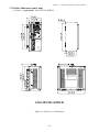
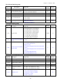
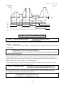
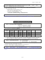
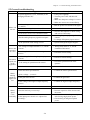
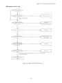
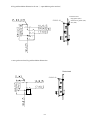
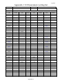
1
Microprocessor Controlled
I G B T Drive
Inverter Motor Speed Regulator
Operating Manual
S310 Serise
200V class
0.4~1.5KW
(0.88~2.9KVA)
S310
Table of Contents
Chapter 0
0.1
0.2
Chapter 1
1.1
Chapter 2
Chapter 3
3.1
3.2
3.3
3.4
3.5
3.6
3.7
Chapter 4
4.1
4.2
4.3
Chapter 5
5.1
5.2
5.3
5.4
5.5
Chapter 6
6.1
6.2
AppendixⅠ
Preface
Preface
Product Inspection
Safety Precautions
Operation Precautions
1.1.1 Before Power UP
1.1.2 During Power UP
1.1.3 Before Operation
1.1.4 During Operation
1.1.5 During Maintenance
Definition of Model
Ambient Environment and Installation
Environment
Environmental Precautions
Electrical Installation
3.3.1 Wiring guidelines
3.3.2 Contactor and Circuit Breaker specification and wiring
3.3.3 Precautions for Peripheral Applications
Specifications
3.4.1 Product Specifications
3.4.2 General Specifications
Wiring Diagram S310 Series Inverter
Description of connection terminals
Outline Dimension
Software Index
Keypad Description
S310 Programmable Functions List
Parameter Function Description
Troubleshooting and Maintenance
Error Display and Corrective Action
5.1.1 Error Display and Corrective Action
5.1.2 Special conditions
5.1.3 Operation errors
5.1.4The instructions for the Power and Alarm LED of the inverter
General Troubleshooting
Quick troubleshooting of S310 series
Routine and periodic inspection
Maintenance and Inspection
Peripheral Components
AC reactor and DC reactor specification at input side
Digital operator and extension cable
S310 Parameters Setting List
i
0-1
0-1
0-1
1-1
1-1
1-1
1-2
1-2
1-2
1-3
2-1
3-1
3-1
3-2
3-3
3-3
3-4
3-5
3-8
3-8
3-8
3-10
3-11
3-13
4-1
4-1
4-3
4-11
5-1
5-1
5-1
5-2
5-3
5-3
5-4
5-5
5-11
5-12
6-1
6-1
6-1
App1
Index of Figures
Figure 2-1 Inverter Nameplate .....................................................................................2-1
Figure 3-1 Panel and enclosure arrangement for S310 inverters ...................................3-1
Figure 3-2 Din rail mounting of the S310 inverter.........................................................3-1
Figure 3-3 Typical Installation Schematic.....................................................................3-5
Figure 3-4a) Installation Examples...............................................................................3-6
b) Installation Examples Using a Filter and Isolation transformer ................3-6
c) Installation Examples with Adjacent Signal Conductors ...........................3-6
Figure 3-5 Control Cable requirements ........................................................................3-7
Figure 3-6 Grounding Examples ..................................................................................3-7
Figure 3-7 Wiring Diagram.......................................................................................... 3-10
Figure 3-8 Power Input Locations ................................................................................ 3-12
Figure 3-9 Frame size 1 Dimensions ............................................................................. 3-13
Figure 3-10 Frame size 2 Dimensions ........................................................................... 3-14
Figure 3-11 Frame size 3 Dimensions ........................................................................... 3-15
Figure 3-12 Frame size 4 Dimensions ........................................................................... 3-16
Figure 3-13 Frame size 5 Dimensions ........................................................................... 3-17
Figure 3-14 Frame size 6 Dimensions ........................................................................... 3-18
Figure 4-1 Keypad Layout ...........................................................................................4-1
Figure 4-2 LED Keypad Operations Sequence..............................................................4-2
Figure 4-3 Frequency reference limits .......................................................................... 4-11
Figure 4-4 Terminal Board Drive Operation Modes ..................................................... 4-12
Figure 4-5 3-Wires Start/Stop Wiring........................................................................... 4-12
Figure 4-6 Drive Start/Stop Operation sequences ......................................................... 4-12
Figure 4-7 Frequency within specified range example................................................... 4-15
Figure 4-8 Frequency outside of range example............................................................ 4-15
Figure 4-9 Frequency at or below specified range example ........................................... 4-15
Figure 4-10 Analog scaling examples .................................................................................... 4-16
Figure 4-11 DC Injection Braking Example.......................................................................... 4-20
Figure 4-12 Custom V/F settings ............................................................................................ 4-21
Figure 4-13 V/F curve with torque boost ............................................................................... 4-22
Figure 4-14 Single cycle auto run ........................................................................................... 4-27
Figure 4-15 Periodic cycle auto run........................................................................................ 4-27
Figure 4-16 Single cycle auto run: final step hold................................................................. 4-28
Figure 4-17 AUTO_RUN cycle with interrupt ...................................................................... 4-28
Figure 5-1 S310 Fault Display and Troubleshooting Flow Chart .......................................5-6
Figure 5-2 OC, OL Fault Display Flow Chart.......................................................................5-7
Figure 5-3 OV, LV Fault Display Flow Chart.......................................................................5-8
Figure 5-4 Motor RUN failure Flow chart ........................................................................... 5-9
Figure 5-5 Motor Overheat Troubleshooting Flow Chart ................................................... 5-10
Figure 5-6 Motor Instability Troubleshooting Flow Chart ............................................ 5-10
Figure 6-1 Digital Operator Extension Cable........................................................................6-1
ii
Preface
Chapter 0 Preface
0.1 Preface
To extend the performance of the product and ensure personnel safety, please read this
manual thoroughly before using the inverter. Should there be any problem in using the
product that can not be solved with the information provided in the manual, contact your
nearest TECO’s technical or sales representative who will be willing to help you.
※Precautions
The inverter is an electrical product. For your safety, there are symbols such as “Danger”,
“Caution” in this manual as a reminder to pay attention to safety instructions on handling,
installing, operating, and checking the inverter. Be sure to follow the instructions for
highest safety.
Danger
Indicates a potential hazard that could cause death or serious personal
injury if misused.
Caution
Indicates that the inverter or the mechanical system might be damaged
if misused.
Danger
z
Do not touch any circuit boards or components after the power is turned off and while
the charging indicator is still lit. (The light will fade)
z Do not make any connections when the inverter is powered on. Do not check parts and
signals on circuit boards during the inverter operation.
z Do not disassemble the inverter or modify any internal wires, circuits, or parts.
● Ground the ground terminal of the inverter properly.
For 200V class ground resistance 100 Ω or below. For 400V class 10Ω or below.
Caution
z
z
z
Do not perform a voltage test on parts inside the inverter. High voltage can destroy the
semiconductor components.
Do not connect U, V, and W terminals of the inverter to any AC input power supply.
CMOS ICs on the inverter’s main board are susceptible to static electricity. Do not
touch the main circuit board
0.2 Product Inspection
TECO inverters have all passed the function test before delivery. Please check the
following when you receive and unpack the inverter:
z The model of the inverter are the same as those specified in your purchase order.
z Check for any damages caused by transportation. Please do not apply power, and
contact a TECO sales representative if any of the above problems occurred.
0-1
Chapter 1 Safety Precautions
Chapter 1
1.1
Safety Precautions
Operation Precautions
1.1.1. Before Power Up
Caution
The line voltage applied must comply with the inverter’s specified input voltage.(See product
nameplate)
Danger
Make sure the main circuit connections are correct. L1, L2 and are power-input terminals and
must not be mistaken for U, V and W. Otherwise, inverter damage can result.
Caution
z To avoid the front cover from disengaging or other damage, do not carry the inverter by its
cover. Support the drive by its heat sink when transporting. Improper handling can
damage the inverter or injure personnel, and should be avoided.
z To avoid the risk of fire, do not install the inverter on flammable objects. Install on
nonflammable objects such as metal surfaces.
z If several inverters are placed in the same control panel, provide heat extraction means to
keep the temperature below 40℃ to avoid overheat or fire hazard.
z When removing or installing the operator keypad, turn OFF the power first, and secure the
keypad correctly to avoid keypad operation or display failure.
Warning
This product is sold subject to IEC 61800-3. In a domestic environment this product may
cause radio interference in which case the user may be required to apply corrective measures.
1-1
Chapter 1 Safety Precautions
1.1.2. During Power Up
Danger
z When the momentary power loss is short, the inverter still has enough storage power to
control the circuit. Therefore, when power is re-applied, the inverter will automatically
restart depending on the setup of 04-03.
z When restarting the inverter, the operation of the inverter is based on the setup of 00-03
and 04-09 and the condition of external switch (FWD/REV button). Attention: the start
operation will be regardless of 04-03.
1. When 00-03 =0, the inverter will not automatically run after restart.
2. When 00-03 =1 and the external switch (FWD/REV button) is OFF, the inverter will
not run after restart.
3. When 00-03 =1, the external switch (FWD/REV button) is ON, and 04-09=0, the
inverter will run automatically after restart.
Attention: To ensure safety, please turn off the external switch (FWD/REV button) after
power loss, to protect machines from possible damage and potential injury to personnel
on sudden resumption of power.
z If 4-09 is set to 0 (direct start up), please refer to the description and warnings for
to verify the safety of operator and machine.
04-09
1.1.3. Before Operation
Danger
Make sure the model and inverter capacity are the same as that set in parameter 12-00.
Caution
On power up the supply voltage set in parameter 05-03 will flash on display for 2 seconds.
1.1.4. During Operation
Danger
Do not connect or disconnect the motor during operation. Otherwise, the over-current will
cause the inverter to trip or damage the unit.
1-2
Chapter 1 Safety Precautions
Danger
z
To avoid electric shock, do not take the front cover off when power is on.
z
The motor will restart automatically after stop when auto-restart function is on. In this
case, use caution while working near the drive, motor, or driven equipment.
Note: The stop push button and external stop command have no safety function.
z
For Emergency stop, it is necessary to use a correct latch type push button and an
appropriate circuit or devices to ensure safety.
Caution
z
Do not touch heat-generating components such as heat sinks and braking resistors.
z
The inverter can drive the motor from low speed to high speed. Verify the allowable speed
range of the motor and the load before operation.
z
Note the settings related to the braking unit.
z
Do not check signals on circuit boards while the inverter is running.
Caution
Allow 5 minutes after disconnecting power before disassembling or checking the components.
The power led should not be illuminated.
1.1.5. During Maintenance
Caution
The Inverter can be used in environment in temperature range from14˚-104℉ (-1040℃) and relative humidity of 95%.
Inverter Disposal
Caution
z
Please dispose of this unit with care as an industrial waste and according to your required
local regulations.
z
The capacitors of inverter main circuit and printed circuit board are considered as
hazardous waste and must not be burnt.
z
The Plastic enclosure and parts of the inverter such as the top cover board will release
harmful gases if burnt.
1-3
Chapter 2 Description of models
Chapter 2
Inverter model →
Definition of model
MODEL: S310-201-H1BCD
I/P: AC 1PH
Input voltage →
200~240V 50/60Hz
Output specifications→
O/P: AC 3PH 0~240V
1.6 KVA 4.2 A
TECO Electric & Machinery Co.,Ltd
S310 Series
S31
0
-
2
01
-
H
1
B
C
Specification
Supply voltage
Blank: None
H: Standard Type
2: 220V
D
D: Built-in
Keypad Panel
Horsepower
0:Standard
1: custom-made type1
2: custom-made type2
3: custom-made type3
P5: 0.5HP
01: 1.0HP
02: 2.0HP
Power supply
Blank: None
1: single phase
C: Built-in RS485
Blank: None
B:Built-in braking unit
Figure 2-1 Inverter Nameplate
2-1
Chapter 3 Ambient Environment and Installation
Chapter 3 Ambient Environment and Installation
3.1 Environment
The environment will directly affect the proper operation and the life span of the inverter, so install
the inverter in an environment complying with the following conditions:
Ambient temperature: 14-104℉(-10oC - +40oC)
(S310-202Model Ambient temperature : Carrier Frequency >5KHz, Tc≤35℃)
Avoid exposure to rain or moisture.
Avoid direct sunlight.
Avoid oil mist and salinity.
Avoid corrosive liquid and gas.
Keep away from radioactive and
Avoid dust, lint fibers, and small metal
flammable materials.
filings.
Avoid electromagnetic interference (soldering machine, power machine).
Avoid vibration (stamping, punching machine). Add a vibration-proof pad if the situation
cannot be avoided.
If several inverters are placed in the same control panel, provide heat removal means to
maintain temperatures below 40oC.
CONTROL
PANEL
PANEL
S310
S310
(Correct configuration)
fan
fan
S310 CONTROL
Enclosure
Enclosure
S310
(Incorrect configuration)
(Correct configuration)
(Incorrect configuration)
Figure 3-1 Panel and enclosure arrangement for S310 inverters
Place the inverter facing forward and its top facing upward to assist with cooling.
12cm
S310
73000CV
Installing
direction
12cm
5cm
5cm
Air convection
-10oC - +40oC
(a) Front view
5cm
(b) Side view
Figure 3-2 Din rail mounting of the S310 Inverter
3-1
Chapter 3 Ambient Environment and Installation
3.2 Environmental precautions
Do not use the inverter in an environment with the following conditions:
3-2
Chapter 3 Ambient Environment and Installation
3.3 Electrical Installation
3.3.1 Wiring guidelines
A. Tightening torque:
Required Screwdriver Torques are as listed below:
Tightening torque
Horsepower
Power source
Nominal torque for TM1 terminal
0.59/0.08
7.10/8.20
0.5/1/2
200-240V
(LBS-FT / KG-M)
(LBS-IN/KG-CM)
B. Power Cables
Power cables are connected to TM1 terminal block, terminals L1, L2, U, V, W, P1, BR.
Choose power cables according to the following criteria:
(1) Use copper wires only. Correct wire diameters should be based on ratings at 105oC.
(2)For rating voltage of wires, the minimum voltage of 240V class type is 300V.
C. Control Cables
Control cables are connected toTM2 control terminal block.
Choose control cables according to the following criteria:
(1) Use copper wires only. Correct wire diameters should be based on ratings at 105oC.
(2) For rating voltage of wires, the minimum voltage of 200V class type is 300V.To avoid noise
interference, do not route power and control cables in the same conduit or trucking.
(3) Where possible use screened / shielded control cables to minimizes electromagnetic
interference. To avoid ground loops always earth the shield of control cables at one end only.
D. Nominal electrical specifications of the terminal Block TM1:
Horsepower
0.5/1/2
Power source
200-240V
Amps
15
Volts
600
※Note: Nominal values of input and output signals (TM2) – follow the specifications of
class 2 wiring.
3-3
Chapter 3 Ambient Environment and Installation
3.3.2 Contactor and Circuit Breaker specification and wiring.
Molded-case circuit breaker/magnetic contactor
Teco bears no responsibility to service for failures caused by the following conditions:
(1) A molded-case circuit breaker is not installed, or an improper or overrated breaker is used,
between the power source and the inverter.
(2) A magnetic contactor, a phase capacitor, or a burst absorber is connected between the
inverter and the motor.
model :
2P5
201
202
S310-□ □ □ -XXX
Molded-case circuit
breaker made by Taian
Magnetic contactor (MC)
made by Taian
Main circuit terminals
(TM1)
50E
10A
50E
20A
50E
30A
CN-11
Wire gauge 2.0 mm2
terminal screw M3
Signal terminals
(TM2)1~12
Wire gauge 0.75mm2 ( # 18 AWG)
terminal screw M2
Signal terminals
(TM3)1~3
Wire gauge 0.75mm2 ( # 18 AWG)
terminal screw M2
Use three-phase squirrel cage induction motor with capacity suitable for the inverter.
If one inverter is driving several motors, the total current of all motors running simultaneously
must be less than the rated current of the inverter, and each motor has to be equipped with a
proper thermal relay.
Do not add capacitive components, such as a phase capacitors, LC or RC, between the inverter
and the motor.
3-4
Chapter 3 Ambient Environment and Installation
3.3.3 Precautions for peripheral applications:
Power supply:
Make sure the correct voltage is applied to avoid
damaging the inverter.
A molded-case circuit breaker or fused disconnect
must be installed between the AC source and the
inverter
Molded-case circuit breaker:
Use a molded-case circuit breaker that conforms to
the rated voltage and current of the inverter to
control the power ON/OFF and protect the inverter.
Do not use the circuit breaker as the run/stop switch
for the inverter.
Leakage breaker:
Install a leakage breaker to prevent problems caused
by electric leakage and to protect personnel.
Setting current should be 200mA or above and the
operating time at 0.1 second or longer to prevent
malfunctions.
Magnetic contactor:
Normal operations do not need a magnetic contactor.
However a contactor has to be installed in primary
side when performing functions such as external
control and auto restart after power failure, or when
using a brake controller.
Do not use the magnetic contactor as the run/stop
switch of the inverter.
AC reactor for power quality improvement:
When inverters below 200V class 15KW are
supplied with high capacity (above 600KVA) power
source or an AC reactor can be connected to
improve the power performance.
Install fast action fuse:
To ensure the safety of peripheral devices, please
install fast action fuse. Regarding the specification,
please refer to P3-4.
Input noise filter:
A filter must be installed when there are inductive
loads affecting the inverter
Inverter:
Input power terminals L1, and L2 can be used in any
sequence regardless of phase.
Output terminals U, V, and W are connected to U,
V, and W terminals of the motor. If the motor is
reversed while the inverter is set to run forward, just
swap any two terminals of U, V, and W.
To avoid damaging the inverter, do not connect the
input terminals U, V, and W to AC input power.
Connect the ground terminal properly. 200V class:
class 3 grounding, <100Ω.
Figure 3-3 Typical Installation Schematic
3-5
Chapter 3 Ambient Environment and Installation
Make external connections according to the following instruction. Check connections after wiring
to make sure all connections are correct. (Do not use the control circuit buzzer to check connections)
(A) Main circuit’s wiring must be separated from other high voltage or high current power line to
avoid noise interference. Refer to the figures below:
Figure 3-4 a) Installation Examples
Figure 3-4b) Installation Examples using a filter and Isolation transformer
A noise filter in the output of the main circuit can suppress conducted noise.
To prevent radiated noise, the wires should be put in a metal pipe and distance from
signal lines of other control equipment should be more than 30 cm.
MCCB
Metal Box
Metal Pipe
Power Supply
Noise
Filter
Noise
Filter
S310
above
Signal Wire
Controller
Figure 3-4c) Installation Examples with Adjacent Signal Conductors
3-6
Chapter 3 Ambient Environment and Installation
When the connection between the inverter and the motor is too long,consider the voltage
drop of the cables.
Phase-to-phase voltage drop (V) = 3 ×resistance of wire (Ω/km)×length of line (m)×current×10-3.
Carrier frequency must be adjusted based on the motor cable length.
Cable length between the inverter and the motor
Recommended carrier frequency
Below 150ft
Below 300ft
Above 300ft
Below 12KHz Below 8KHz
Below 5KHz
Setting of parameter 10-03
12
8
5
(B) The control circuit wiring must be separated and routed away from the main circuit control line
or other high voltage or current power lines to avoid noise interference
To avoid erroneous operation caused by noise interference, shield the control circuit
wiring with twisted-wires, and connect the shielded wire to a ground terminal. Refer to the
figure below. The wiring distance should not exceed 50 meters.
Shielding sheath
Protective covering
To ground terminal
Do not connect this end
Wrapped with insulating tape
Figure 3-5 Control Cable requirements
(C)Inverter Ground terminal must be connected to installation ground correctly and according to
the required local wiring regulations. For 200V class ground resistance should be 100Ω or less.
Ground cable size must be according to the required local wiring regulations.
the shorter the better.
Do not share the ground of the inverter with other high current loads (welding machine,
high power motor). Connect the terminals to their own ground.
Do not make a loop when several inverters share a common ground point.
Figure 3-6 Grounding Examples
S310
S310
S310
S310
S310
S310
S310
S310
S310
(a) Good
(b) Good
(c) Bad
(D) To ensure maximum safety, use correct wire size for the main power circuit and control circuit.
(According to the required local regulations)
(E) Verify that all wiring is correct, wires are intact, and terminal screws are secured.
3-7
Chapter 3 Ambient Environment and Installation
3.4 Specifications
3.4.1 Product Specifications
Single / Three phase, 200-240V model
S 310-□□□-XXX
2P5
201
202
Horsepower(HP)
0.5
1
2
Max Applicable Motor Output (KW)
0.4
0.75
1.5
Rated Output Current(A)
3.1
4.2
7.5
Rated Capacity(KVA)
0.88
1.60
2.9
Max. Input Voltage
Max. Output Voltage
Sing le Phase: 200 ~240V +10% -15%,50 /60H Z ± 5 %
Sing le Phase: 200 ~240V
Input Current(A)
5.4
10.4
16
Net Weight (KG)
0.97
1.07
Net Weight (KG)(keypad)
1.0
1.1
Allowable momentary power loss
time (second)
1.0
1.0
2.0
3.4.2 General Specifications
Item
S310
Control Mode
V/F
Range
General Control
Frequency Control
Setting resolution
Keypad setting
Display Function
External signal setting
0.01~400.00 Hz
Digital: 0.01Hz, Analog: 0.06Hz/ 60Hz(10bits)
Set directly with▲▼ keys or the VR on the keypad
Five digital LED and status indicator: display frequency /
Inverter parameter/ Fault Log/ Program Version
1. External potentiometer0-10V/ 0-20mA
2. Provides up/down controls, speed control or automatic
procedure control with multifunctional contacts on the
terminal block(TM2)
Frequency Limit
Function
Upper/lower frequency limits
Carrier frequency
1 ~ 12 kHz
V/F pattern
6 fixed patterns, 1programable curve
Acc/Dec control
Acc/Dec time (0.1 ~ 3,600 seconds)
Multifunction analog
output
4 functions (refer to description on 2-12)
Multifunction input
12 functions (refer to description on 01-00~01-04)
Multifunction output
6 functions (refer to description on 01-09)
Momentary Power Loss Restart, Overload Detection, 8 preset
speeds,2/3-wire Control, torque boost, Slip Compensation,
Frequency Upper/ Lower Limit, Modbus slave and PC/PDA Link,
Auto Restart.
Other Functions
3-8
Chapter 3 Ambient Environment and Installation
Communication Control
Braking Torque
About 20﹪, standard model the specified external braking
resistors can provide 100%
Operation temperature
14-104℉(-10 ~ 40℃)
Storage temperature
4-140℉(-20 ~ 60℃)
Humidity
0 – 95% Relative Humidity(Non-condense)
Vibration
1G (9.8m/s2 )
Enclosure
IP20
FUSE protection
Protective Functions
1. Control by RS485
2. One to one or one to many (RS485 ONLY) control.
3. BAUD RATE/STOP BIT/PARITY/bit can be set
The motor stops after FUSE melt
Over Voltage
200V class: DC Voltage>410V
Under Voltage
200V class: DC Voltage<190V
Momentary Power
Loss Restart
Other Function
Restart can be initiated with spin start .
Over torque detection, error contact control, reverse prohibit,
prohibit for direct start after power up and error recovery.
3-9
Chapter 3 Ambient Environment and Installation
3.5 Wiring diagram S310 series inverter
220V:0.5~2HP
Ground
Resistance<100Ω
3
2
1
Figure 3-7 Wiring Diagram
Note 1: Please refer to description of main circuit terminals (P1, BR) and specification of braking
resistor for value selection.
2: Dashed box built-in or none, please refer to CH2 Definition of model
3: Please avoid connecting output of inverter to the earth.
3-10
Chapter 3 Ambient Environment and Installation
3.6 Description of connection terminals
Descriptions of main circuit terminals
Symbol
L1
L2
BR
P1
U
V
W
Description
Main power input.
single phase :L1 / L2
Braking resistor connection terminal: Used in
For
applications when it is required to stop a high inertia load
200V class:0.5~2HP,
rapidly. (refer to specifications of the braking resistor)
Inverter outputs
Descriptions of S310 control circuit terminals
Symbol
Description
Normal close contact
RB
Multifunctional output
terminals
Normal open contact
RA
Contact rated capacity:
(250VAC/1A or30VDC/1A)
Contact using description:(refer
to parameters 01-09)
10V
Frequency knob (VR) power source terminal (pin 3)
AIN
Analog frequency signal input terminal (0~10VDC/4~20mA)
COM
Common for digital input signal for S1~S5 input.
FM+
The positive multifunction analog output signal for multifunction (refer to parameter
2-12 description), the signal for output terminal is 0-10VDC (below 2mA).
S1
S2
S3
S4
S5
A
B
SG
multifunction input terminals(refer to parameter 1-00~1-04 description)
(+) RS485 communication applications
(- ) RS485 communication applications
Ground(RS485)
3-11
Chapter 3 Ambient Environment and Installation
200V class: 0.5 ~ 2HP
L1 L2 BR P1 U V W
To Motor
Power
Figure 3-8 Power Input Locations
Descriptions of JUMPER function
JP2/JP3
○ 3
○ 2
○ 1
Type of external signal
Remarks
4~20mA analog signal
Effective when
External control
○ 3
○ 2
○ 1
00-05=2
0~10VDC analog signal
3-12
Chapter 3 Ambient Environment and Installation
3.7 Outline Dimension (unit: mm)
(1) Frame1 : single phase S310-2P5/201-H1BCD
CAUTION:
Do not inspect
components unless
"power" lamp is off.
See manual for
proper installation
and operation.
S310-2P5/201-H1BCD
Figure 3-9 Frame size 1 Dimensions
3-13
Chapter 3 Ambient Environment and Installation
(2) Frame2 : Single phase : S310-2P5/201-1D
CAUTION:
Do not inspect
components unless
"power" lamp is off.
See manual for
proper installation
and operation.
S310-2P5/201-H1D
Figure 3-10 Frame size 2 Dimensions
3-14
Chapter 3 Ambient Environment and Installation
(3) Frame3 : Single phase : S310-2P5/201-H1
CAUTION:
Do not inspect
components unless
"power" lamp is off.
See manual for
proper installation
and operation.
S310-2P5/201-H1
Figure 3-11 Frame size 3 Dimensions
Note:
model
unit
S310-201/2P5-H1D
S310-201/2P5-H1BCD
S310-201/2P5-H1
√:built-in
Breaking unit
×
√
×
RS485
×
√
×
×:None
3-15
keypad
√
√
×
fan
×
×
×
Chapter 3 Ambient Environment and Installation
(4) Frame4 : Single phase : S310-202-H1BCD
79±0.3
79
㊣0.3
69±0.3
69㊣0.3
152±0.4
152㊣0.4
133±0.4
133㊣
0.4
108±0.3
108㊣
0.3
2Φ 4.5
2-?
4.5
Se e manual before
operation
C ut-off t he power
and wait for 5 minutes
before inspecting
components
4.5±0.1
4.5㊣0.1
59±0.3
59㊣0.3
133±0.4
133㊣0.4
4.83±0.1
4.83㊣0.1
145±0.4
145㊣0.4
75.75±0.3
73.75㊣0.3
87.75±0.3
87.75㊣0.3
160±0.4
160㊣0.4
S310-202-H1BCD
Figure 3-12 Frame size 4 Dimensions
3-16
Chapter 3 Ambient Environment and Installation
(5) Frame5 : Single phase : S310-202-H1D
2Φ
2-?4.5
4.5
152±0.4
152㊣0.4
108±0.3
108㊣0.3
133±0.4
133㊣0.4
79±0.3
79㊣0.3
69±0.3
69㊣0.3
Se e manual before
operation
C ut-off t he power
and wait for 5 minutes
before inspecting
components
4.5±0.1
4.5㊣0.1
59±0.3
59㊣0.3
133±0.4
133㊣0.4
4.83±0.1
4.83㊣0.1
145±0.4
145㊣0.4
73.75±0.3
73.75㊣0.3
87.75±0.3
87.75㊣0.3
160㊣0.4
160±0.4
S310-202-H1D
Figure 3-13 Frame size 5 Dimensions
3-17
Chapter 3 Ambient Environment and Installation
(6) Frame6 : Single phase : S310-202-H1
2Φ
2-?4.5
4.5
152±0.4
152㊣0.4
108±0.3
108㊣0.3
133±0.3
133㊣0.4
69±0.3
69㊣0.3
CAUTION
See manual before
operation
Cut-o ff th e power
and wait for 5 minutes
b ef o r e i n s pe ct ing
components
74±0.3
74㊣0.3
88±0.3
88㊣0.3
145±0.4
145㊣0.4
133±0.4
133㊣0.4
4.83±0.1
4.83㊣0.1
4.5㊣0.1
4.5±0.1
59±0.3
59㊣0.3
160±0.4
160㊣0.4
S310-202-H1
Figure 3-14 Frame size 6 Dimensions
Note:
model
unit
S310-202-H1D
S310-202-H1BCD
S310-202-H1
√:built-in
Breaking unit
×
√
×
RS485
×
√
×
×:None
3-18
keypad
√
√
×
fan
√
√
√
Chapter 4 Software Index
Chapter 4
Software Index
4.1 Keypad Description
Figure 4-1 Keypad Layout
1. Four actions of FUN mode: Hz/RPM, and display of five 7-segment display. (Refer to operation
description of the keypad).
2. FWD LED: Forward Direction, LED action (Flash while stopped, solid Lit during operation).
3. REV LED: Reverse Direction, LED action (Flash while stopped, solid Lit during operation).
Caution
To avoid keypad damage, do not operate it with a screwdriver or any sharp and hard tool.
4-1
Chapter 4 Software Index
4 Operation Instruction of the LED keypad
●
Power On
: LED fully Lit
: LED flashing
2 seconds later or after Enter operation signal, Press DSP to modify the display
HZ/RPM
‧
HZ/RPM
‧
HZ/RPM
‧
☉
FUN
—
FUN
☉
FUN
—
FUN
If nothing was done in parameter list menu or parameter data menu for
3 minutes, automatically returns to main menu(frequence menu).
Figure 4-2 LED Keypad Operations Sequence
5.The instructions for the Power and Alarm LED of the inverter are as follows:
Power indicator light:
On power up, Power LED action, otherwise Power LED Turn off
Alarm indicator light:(note1:)
a. When the inverter have mistakes which cannot be reseted, such as:
CTER,EPR,OH,LV,OV,OC,the Alarm LED flashes quickly
b. When the inverter have mistakes which can be reseted, such as:
OH-C, OV-C, OC-S, OC-d, OC-C, OC-a, OL2, OL1, the Alarm LED flashes slowly
4-2
Chapter 4 Software Index
4.2 S310 Programmable Functions List
Parameter
Group No.
Description
00-
The basic parameters group
01-
External terminal digital signal input function group
02-
External terminal analog signal input function group
03-
Preset Frequency function group
04-
Start/Stop command group
05-
V/F command group
07-
Protection function group
08-
Communication function group
10-
Assistant function group
11-
Keypad display group
12-
User parameter group
13-
Auto Run(Auto Sequencer) function group
0- The basic parameters group
Function
Description
Code No.
00-00 ----00-01 Volts/Hz Patterns (V/F)
Range/Code
00-02
Motor rotation
00-03
Main Run
Command Source Selection
00-04
-----
00-05
Main Frequency
Command Source Selection
00-06
-----
----1~7
0:Forward
1:Reverse
0: Keypad
1: External Run/Stop Control
2: Communication
----0: Keypad
1: Potentiometer on Keypad
2: External AI1 Analog Signal Input
3: Communication Control
-----
00-07
Frequency Upper Limit (Hz)
0.01~400.00
00-08
00-09
00-10
Frequency Lower Limit (Hz)
Acceleration Time 1(S)
Deceleration Time 1(S)
00-11
Operation modes for external
terminals
0.01~399.99
0.1~3600.0
0.1~3600.0
0: Forward/Stop-Reverse/Stop
1: Run/Stop-Forward/Reverse
2: 3-Wire Control Mode-Run/Stop
3:4 –Wire pulse Control Mode-Run/Stop
1.00~25.00
00-12
00-13
00-14
Jog Frequency (Hz)
Jog Acceleration Time (MFIT)
(Seconds)
Jog Deceleration Time (MFIT)
(Seconds)
Factory
Setting
----1/4
0
Remarks
Reserved
*1
0
-----
Reserved
0
----50.00
/60.00
0.00
10.0
10.0
Reserved
*1
*1
0
2.00
*1
0.1~25.5
0.5
*1*6
0.1~25.5
0.5
*1*6
4-3
Chapter 4 Software Index
1- External terminal digital signal input function group
Function
Code No.
01-00
01-01
01-02
01-03
Multifunction Input Term. S1
Multifunction Input Term. S2
Multifunction Input Term. S3
Multifunction Input Term. S4
01-04
Multifunction Input Term. S6
01-05
Catch up / slow Down Value
Description
Multifunction terminal S1~ S5
01-06
confirm the
scan times
01-07~01-08 -----
01-09
01-11
01-12
01-13
Range/Code
0: Forward/Stop Command
1: Reverse/Stop Command
2: Preset Speed unit 0 (3-02)
3: Preset Speed unit 1 (3-03)
4: Preset Speed unit 2 (3-05)
5: Jog Command
6: Emergency Stop
7: Base Block
8: Reset
9: Auto _ Run Mode
10:Catch up*6 11:slow Down*6
Factory
Remarks
Setting
0
1
5
6
8
0 ~ 100(%)
20
1 ~ 200(×2ms)
10
----0: Run
1: Frequency Reached
2: Fault
3: Set Frequency
Output Relay RY1 Operation Mode
4: Frequency Threshold Level
(> 1-11) - Frequency Reached
Frequency Threshold Level
(< 1-11) - Frequency Reached
Frequency Output Setting (Hz)
0.00 ~ 400.00
Frequency Detection Range
0.00 ~ 30.00
xxxx0: S1 NO xxxx1: S1 NC
xxx0x: S2 NO xxx1x: S2 NC
S1~ S5 switch type select
xx0xx: S3 NO xx1xx: S3 NC
x0xxx: S4 NO x1xxx: S4 NC
0xxxx: S5 NO 1xxxx: S5 NC
-----
*6
Reserved
0
0.00
2.00
*1
*1
00000
*6
※ “NO”: Normal open, “NC”: Normal close.
2- External terminal analog signal input function group
Function
Description
Code No.
Factory
Setting
Range/Code
02-00
AIN analog Input signal type select 0: 0 ~ 10V
02-01
AIN Signal Verification Scan
1 ~ 200(×2ms)
100
02-02
AIN Gain (%)
0 ~200
100
*1
02-03
AIN Bias (%)
0 ~100
0
*1
02-04
AIN Bias Selection
0: Positive
1: Negative
0
*1
02-05
AIN Slope
0: Positive
1: Negative
0
*1
0
*1
100
*1
02-06~02-11
1: 4 ~ 20mA
Remarks
0
Reserved
02-12
Analog Output Mode(FM+)
02-13
Analog Output FM+ Gain (%)
0: Output Frequency
1: Frequency Setting
2: Output Voltage
3: DC Bus Voltage
0 ~200
4-4
Chapter 4 Software Index
3-preset Frequency function group
Function
CodeNo.
Description
Range/Code
Factory
Remarks
Setting
0: common
03-00
Preset Speed Control mode
Selection
(Is uniform time( Acc1/Dec1)
1: special
0
*1
(is single time Acc0/Dec0~ Acc7/Dec7)
Keypad
03-01
Preset Speed 0 (Hz)
0.00 ~ 400.00
5.00
03-02
Preset Speed1 (Hz)
0.00 ~ 400.00
5.00
*1
03-03
Preset Speed2 (Hz)
0.00 ~ 400.00
10.00
*1
03-04
Preset Speed3 (Hz)
0.00 ~ 400.00
20.00
*1
03-05
Preset Speed4 (Hz)
0.00 ~ 400.00
30.00
*1
03-06
Preset Speed5 (Hz)
0.00 ~ 400.00
40.00
*1
03-07
Preset Speed6 (Hz)
0.00 ~ 400.00
50.00
*1
03-08
Preset Speed7 (Hz)
0.00 ~ 400.00
60.00
*1
03-09
-----
-----
-----
Reserved
03-10
-----
-----
-----
Reserved
03-11
-----
-----
-----
Reserved
03-12
-----
-----
-----
Reserved
03-13
-----
-----
-----
Reserved
03-14
-----
-----
-----
Reserved
03-15
-----
-----
-----
Reserved
03-16
-----
-----
-----
Reserved
03-17
Preset Speed0-Acctime(s)
0.1 ~ 3600.0
10.0
*1
03-18
Preset Speed0-Dectime(s)
0.1 ~ 3600.0
10.0
*1
03-19
Preset Speed1-Acctime(s)
0.1 ~ 3600.0
10.0
*1
03-20
Preset Speed1-Dectime(s)
0.1 ~ 3600.0
10.0
*1
03-21
Preset Speed2-Acctime(s)
0.1 ~ 3600.0
10.0
*1
03-22
Preset Speed2-Dectime(s)
0.1 ~ 3600.0
10.0
*1
03-23
Preset Speed3-Acctime(s)
0.1 ~ 3600.0
10.0
*1
03-24
Preset Speed3-Dectime(s)
0.1 ~ 3600.0
10.0
*1
03-25
Preset Speed4-Acctime(s)
0.1 ~ 3600.0
10.0
*1
03-26
Preset Speed4-Dectime(s)
0.1 ~ 3600.0
10.0
*1
03-27
Preset Speed5-Acctime(s)
0.1 ~ 3600.0
10.0
*1
03-28
Preset Speed5-Dectime(s)
0.1 ~ 3600.0
10.0
*1
03-29
Preset Speed6-Acctime(s)
0.1 ~ 3600.0
10.0
*1
03-30
Preset Speed6-Dectime(s)
0.1 ~ 3600.0
10.0
*1
03-31
Preset Speed7-Acctime(s)
0.1 ~ 3600.0
10.0
*1
03-32
Preset Speed7-Dectime(s)
0.1 ~ 3600.0
10.0
*1
4-5
Freq
Chapter 4 Software Index
04-start/stop command group
Function
Code No.
Description
Range/Code
04-00
-----
-----
04-01
Stopping Method Selection
0: Enhanced braking capacity
1: Coast to stop
04-02
-----
-----
Factory
Setting
Remarks
-----
Reserved
0
-----
Reserved
0: Momentary Power Loss and Restart disable
04-03
Momentary Power Loss and
1: Momentary power loss and restart enable while
Restart
CPU is operating. (According to the capacity of
0
DC power)
04-04~
04-07
-----
-----
04-08
Reset Mode Setting
04-09
Direct Running After Power Up
04-10~ ----04-14
04-15
04-16
04-17
04-18
DC Injection Brake Start
-----
0: Enable Reset Only when Run Command is Off
Reserved
0
1: Enable Reset when Run Command is On or Off
0: Enable Direct running after power up
1
1: Disable Direct running after power up
-----
-----
0.10 ~ 10.00
1.50
Reserved
Frequency (Hz) @stopped
DC Injection Brake Level (%)
0 ~ 20
5
@Stopped
DC Injection Brake Time
0.0 ~ 25.5
0.5
(Seconds) @stopped
DC Injection Brake @running
0:DC Injection Brake @running enable
0
1:DC Injection Brake @ running disable
*6
05-V/F command group
Function
Code No.
Description
Range/Code
Factory
Setting
05-00
Volts/Hz Curve Modification(Torque Boost) (%) 0 ~ 30.0
0.0
05-01
-----
-----
-----
05-02
Motor rated Slip Compensation (%)
0.0 ~ 100.0
0.0
05-03
v/f max voltage
198.0~256.0
220.0
05-04
Maximum Frequency (Hz)
0. 20 ~ 400.00
50.00/60.00
05-05
Maximum Frequency Voltage Ratio (%)
0.0 ~ 100.0
05-06
Medium Frequency2 (Hz)
0.10 ~ 400.00
05-07
Medium Frequency Voltage Ratio2 (%)
0.0 ~ 100.0
50.0
05-08
Medium Frequency1 (Hz)
0. 10 ~ 400.00
10.00/12.00
05-09
Medium Frequency Voltage Ratio1 (%)
0.0 ~ 100.0
05-10
Minimum Frequency (Hz)
0. 10 ~ 400.00
05-11
Minimum Frequency Voltage Ratio (%)
0.0 ~ 100.0
4-6
100.0
25.00/30.00
20.0
0.50/0.60
1.0
Remarks
Reserved
Chapter 4 Software Index
07-Protection function group
Function
Code No.
07-00
07-01
07-02
07-03
07-04
07-05
07-06
07-13
Description
Trip Prevention Selection
Trip Prevention Level
During Acceleration (%)
Trip Prevention Level
During Deceleration (%)
Trip Prevention Level In
Run Mode (%)
over voltage Prevention
Level in Run Mode
Electronic Motor Overload
Protection Operation Mode
Motor Rated Current
(Amp AC)
OH over heat Protection
( cooling fan control)
Factory
Setting
Range/Code
xxxx0: Enable Trip Prevention During Acceleration
xxxx1: Disable Trip Prevention During Acceleration
xxx0x: Enable Trip Prevention During Deceleration
xxx1x: Disable Trip Prevention During Deceleration
xx0xx: Enable Trip Prevention in Run Mode
xx1xx: Disable Trip Prevention in Run Mode
x0xxx: Enable over voltage Prevention in Run Mode
x1xxx: Disable over voltage Prevention in Run Mode
00000
50 ~ 200
200
50 ~ 200
200
50 ~ 200
200
80 VDC ~ 100VDC
100
0: Enable Electronic Motor Overload Protection
1: Disable Electronic Motor Overload Protection
Remarks
1
*6
---0: Auto (Depends on temp.)
1: Operate while in RUN mode
2: Always Run
3: Disabled
1
*6
Factory
Setting
Remarks
1
*2*3
----0:4800
1:9600
2:19200
3:38400
0:1 Stop Bit
1:2 Stop Bits
0:Without Parity
1:With Even Parity
2:With Odd Parity
0: 8-Bits Data
1: 7-Bits Data
-----
Reserved
2
*2*3
0
*2*3
0
*2*3
0
*2*3
0.0 ~ 25.5
0.0
08-Communication function group
Function
Code No.
Description
08-01
Assigned Communication
Station Number
-----
08-02
Baud Rate Setting (bps)
08-03
Stop Bit Selection
08-04
Parity Selection
08-05
Data Format Selection
08-06
Communication time-out
detection time
08-07
Communication time-out
operation selection
08-08
Err6 fault tolerance times
08-00
Range/Code
1~ 32
0:Deceleration to stop
1:Coast to stop
2: continue operating.
1 ~ 20
4-7
0
3
Chapter 4 Software Index
10-Assistant function group
Function
Code No.
10-00
-----
Description
10-01
Reverse operation control
10-02
10-03
----Carrier Frequency (kHz)
10-04
Carrier mode Selection
10-16
AVR Control
Range/Code
----0: Reverse command is enabled
1: Reverse command is disabled
----1~ 12
0: Carrier mode0
1: Carrier mode1
2: Carrier mode2
0: AVR function effective
1: AVR function ineffective
Factory
Setting
-----
Remarks
Reserved
0
----5
Reserved
1
0
*6
Factory
Setting
Remarks
00000
*1
11-Keypad display group
Function
Description
Code No.
11-00
11-01
11-02
Display Mode
Range/Code
xxxx0: Disable Motor Current Display
xxxx1: Enable Motor Current Display
xxx0x: Disable Motor Voltage Display
xxx1x: Enable Motor Voltage Display
xx0xx: Disable Bus Voltage Display
xx1xx: Enable Bus Voltage Display
x0xxx: Disable temperature Display
x1xxx: Enable temperature Display
Custom Units (Line Speed)
0 ~ 65535
1500/1800
Value
0: Drive Output Frequency is Displayed
1: Line Speed is Displayed in
Integer (xxxxx)
2: Line Speed is Displayed with One Decimal Place
Custom Units (Line Speed)
0
(xxxx.x)
Display Mode
3: Line Speed is Displayed with Two Decimal Places
(xxx.xx)
4: Line Speed is Displayed with
Three Decimal Places (xx.xxx)
*1
*1
12-User parameter group
Function
Description
Code No.
12-00
Drive Horsepower Code
12-01
Software Version
12-02
-----
Fault Log (Last 3 Faults)
12-03~12-05 ----Reset Drive to Factory
12-06
Settings
12-07
Factory
Setting
---------
Range/Code
Parameter Lock
----1150: Reset to the 50Hz factory setting
1160: Reset to the 60Hz factory setting
0: Enable all Functions
1: 03-01~03-08 cannot be changed
2: All Functions cannot be changed
Except 03-01~ 03-08
3: Disable All Function
4-8
Remarks
*3
*3
-----
*3
-----
Reserved
0000
0
*6
Chapter 4 Software Index
13-Auto Run function group
Function
Description
Code No.
13-00
13-01
13-02
13-03
13-04
13-05
13-06
13-07
13-08~
13-15
13-16
13-17
13-18
13-19
13-20
13-21
13-22
13-23
13-23~
13-31
13-32
13-33
Factory
Remarks
Setting
Range/Code
0: Disabled.
1: Single cycle. (Continues to run from the
unfinished step if restarted).
2: Periodic cycle. (Continues to run from the
unfinished step if restarted).
Auto Run( sequencer) mode
3: Single cycle, then holds the speed Of final step to run.
selection
(Continues to run from the unfinished step if restarted).
4: Single cycle. ( starts a new cycle if restarted).
5: Periodic cycle. ( starts a new cycle if restarted).
6: Single cycle, then hold the speed of final step to run.
( starts a new cycle if restarted).
Auto _ Run Mode
Frequency Command 1
Auto _ Run Mode
Frequency Command 2
Auto _ Run Mode
Frequency Command 3
0.00 ~ 400.00 (Hz)
Auto _ Run Mode
Frequency Command 4
Auto _ Run Mode
Frequency Command 5
Auto _ Run Mode
Frequency Command 6
Auto _ Run Mode
Frequency Command 7
Reserved
0
0.00
Reserved
Auto_ Run Mode Running
Time Setting 0
Auto_ Run Mode Running
Time Setting 1
Auto_ Run Mode Running
Time Setting 2
Auto_ Run Mode Running
0.0 ~ 3600.0 (second)
Time Setting 3
Auto_ Run Mode Running
Time Setting 4
Auto_ Run Mode Running
Time Setting 5
Auto_ Run Mode Running
Time Setting 6
Auto_ Run Mode Running
Time Setting 7
Reserved
0.0
Reserved
Auto_ Run Mode Running 0:stop
1: forward
Direction 0
Auto_ Run Mode Running 2: reverse
Direction 1
0
4-9
Chapter 4 Software Index
13-34
13-35
13-36
13-37
13-38
13-39
Auto_ Run Mode Running
Direction 2
Auto_ Run Mode Running
Direction 3
Auto_ Run Mode Running
Direction 4
Auto_ Run Mode Running
Direction 5
Auto_ Run Mode Running
Direction 6
Auto_ Run Mode Running
Direction 7
※Notes: *1 Can be modified during run
*2 cannot be modified while communication is active
*3 do not change while making factory setting
*4 the parameter will be changed by replacing model
*5 only for version 1.1 and above
*6 only for version V1.2 and above
4-10
Chapter 4 Software Index
4.3 Parameter Function Description
Group0- The basic parameters group
00-01:Volts/Hz Patterns (V/F)
=1~7
1.00-01=1~6 F Patt V /ern. (Refer to group5), 00-01=7 Flexiable V/F pattern.
00-02:Motor rotation = 0:forward
=1:reverse
Note:when10-01is set to 1, 00-02 is not set to1, keypad display” LOC”.
00-03: Main Run Command Source Select
=0:Keypad =1: External Run/Stop Control
=2: Communication
1. 00-03=0, the inverter is controlled by the keypad.
2. 00-03=1, the inverter is controlled by the external terminals, and the Stop key for emergency stop
is operational.
※Note:00-03, please refer to parameter 04-03 for detailed description in order to ensure safety of
operators and machines.
3. 00-03=2, the inverter is controlled by Communication.
00-05: Main Frequency Command Source Select
=0: UP/DOWN of Keypad
=1:Potentiometer on Keypad
=2: External AIN Analog Signal Input
=3: External Up/Down Frequency Control
1. The priority in reading frequency is Jog> preset speed>▲▼ on keypad or Up / Down or External
AIN Analog Signal Input or communication control.
Internal frequency
00-07: Frequency Upper limit(Hz) =0.01
00-08: Frequency Lower limit(Hz) =0.01
~
~
400.00
400.00
00-07 (upper frequency limit)
00-08 (lower frequency
(Note)
Figure 4-3 Frequency reference limits
※Note: When 00-08 = 0 Hz and frequency command is 0 Hz; the inverter will stop at 0 speed.
When 00-08 > 0 Hz and frequency command ≦00-08, the inverter will output the
00-08 preset value.
00-09: Acceleration time(S) =0.1
~
3600.0
00-10: Deceleration time(S) =0.1
~
3600.0
1. Formula for calculating acceleration and deceleration time: The denominator is base on the
rated frequency of motor.
00- 09×preset frequency
accel er at i on t i me =
05-04
0
010
×
pr
eset
f r equency
deceleration time =
05− 04
4-11
Chapter 4 Software Index
00-11: Operation modes for external terminals
=0:Forward/stop-reverse/stop
=1:Run/stop-forward/reverse
=2:3-wire control mode -run/stop =4: 4-wire control mode -run/stop
1.) When operation command 00-03 = 1 (external terminal), 00-11is valid.
2.) When operation command 00-03 = 1 (external terminal control), the stop button for emergency is available.
3.) That both forward and reverse commands are ON will be treated as STOP.
Figure 4-4 Terminal Board Drive Operation Modes
3、00-11 = 2, Control mode is as below:
S1 (RUN)
S2 (STOP)
S3 (FWD/REV)
COM
Figure 4-5 3-Wire start/stop wiring
Figure 4-6 Drive start/stop operation sequences
※Note: 1.As 3 wire control mode is selected, the terminal S1, S2 and S3 is not controlled by 01-00,
01-01 and 01-02.
2. 10-01=1, the reverse command is unavailable.
3.As 4 wire control mode is selected, the terminal S1, S2 and S3, S4 is not controlled by 01-00, 01-01
and 01-02, 01-03.
00-12:
00-13:
00-14:
Jog Frequency (Hz) =1.00 ~ 25.00
Jog Acceleration Time (MFIT) (Seconds)
Jog Deceleration Time (MFIT) (Seconds)
4-12
=0.1 ~ 25.5
=0.1 ~ 25.5
Chapter 4 Software Index
Group1- External terminal digital signal input function group
Multifunction input terminals (TM2 S1-S5) controlling:
01-00~04:
=0:Forward/Stop Command
=1: Reverse/Stop Command
=2: Preset Speed unit 0 (3-02)
=3: Preset Speed unit 1 (3-03)
=4: Preset Speed unit 2 (3-05)
=5: JOG Command
=6: Emergency Stop
=7: Base Block
=8: reset
=9: Auto _ Run Mode
=10: Catch up
=11: Slow Down
1) The terminals S1- S5 on terminal block (TM2) are multifunction input terminals. The 9 functions
shown above can be set for these terminals.
2) Function Description for 1-00~04:
A. 01-00~04=0/1(Forward/Reverse/Stop)
As forward command is ON , the inverter runs and stops when the command is OFF. The 1-00
factory setting is forward.
As reverse command is ON, the inverter runs and stops when the command is OFF. The 1-01
factory setting is reverse.
B. 01-00~04=2/3/4 (Frequency Command 1/2/4at 3-02/3-03/3-05)
When External multifunction input terminals are ON, the inverter is operates at the preset
speed and the duration is determined by the time the input is ON. The corresponding preset
frequency will be according to preset value of parameters 3-01 to 3-08 and in relation to the
operation of input terminals 2 to 4. As shown in the table below:
Output frequency
preset value
3-01
3-02
3-03
3-04
3-05
3-06
3-07
3-08
Multifunction terminal 3
Preset value =4
0
0
0
0
1
1
1
1
Multifunction terminal 2
Preset value =3
0
0
1
1
0
0
1
1
Multifunction terminal 1
Preset value =2
0
1
0
1
0
1
0
1
C. 01-00~04=5(JOG)
When Jog operation, is selected, the inverter operates at the Jog acceleration and deceleration
times. The corresponding jog frequency parameter is shown below:
The priority order of frequency: Jog Speed→Preset Speed→Keypad frequency or
external frequency signal
D. 01-00~04=6: External Emergency Stop.
The inverter will decelerate to stop by 00-10 setting and Flash E.S as the emergency stop signal
is received regardless of 04-01 setting. After the emergency stop signal is removed, turn the
4-13
Chapter 4 Software Index
RUN switch OFF and then ON again, or press the run key in keypad mode, the inverter will
restart again up and ramps up to the command frequency.
E. 01-00~05=7: Base Block
The inverter immediately stops output, and the motor does a Coast with flashing B.B.
F. 01-00~05=8(Reset Command)
The Reset command is same as the Reset Key on the panel. When the command is OFF, the
inverter does not respond.
G. 01-00~05=9(Auto _ Run Mode)
Set 01-00=9, when the input terminals are ON, the inverter is operates at the Auto _ Run
Mode.
H. 01-00~04=10/11(Catch up/Slow Down)
Increases or Reduces reference value by percentage (relative) set in par. 01-05 Catch up/slow
Down Value.
01-05: Catch up / slow Down Value
=0~100%
Enter a percentage (relative) value to be either added to or deducted from the actual reference
for Catch up or Slow down respectively. actual input frequency command = input frequency +
input frequency× (01-05 setting).
Digital /Analog input signal scan times:
01-06: Multifunction terminal S1 ~ S5 confirm the scan times
=1 ~ 200(×2ms)
1. TM2 terminal is used for scanning. If there are the same signals continuously input for N times, the
inverter will treat the signal as normal. During the signal evaluation, if the scan times are less than N,
the signal will be treated as noise. 2. Each scan period is 8ms.
3. The user can specify the scan times interval duration according to the noise environment. If the
noise is serious, increase the value of 01-06, however the response will be slower.
Multifunction output terminals control:
01-09: Output Relay RY1 Operation Mode (R1C,R1B,R1A terminal )
=0: Run
=1: Frequency Reached
=2: Fault
=3: Set Frequency (01-11 ±01-12)
=4: Frequency Threshold Level(> 1-11) - Frequency Reached
=5: Frequency Threshold Level (< 1-11) - Frequency Reached
01-11: Frequency Reached Output Setting
=0.00 ~ 400.00Hz
01-12: Frequency Detection Range
=0.00 ~ 30.00Hz
01-09/10= 3: Arbitrary frequency consistency Fout = 01-11 ±01-12
Figure 4-7 Frequency within specified range example
4-14
Chapter 4 Software Index
01-09/10= 4: Frequency detection Fout > 01-11
Figure 4-8Frequency outside of range example
01-09/10= 5: Frequency detection Fout < 01-11
Figure 4-9 Frequency at or below specified range example
01-13:
s1~s5 switch type select
=xxxx0: S1 NO
=xxxx1: NC
=xxx0x: S2 NO
=xxx1x: NC
=xx0xx: S3 NO
=xx1xx: NC
=x0xxx: S4 NO
=x1xxx: NC
=0xxxx: S5 NO
=1xxxx: NC
※Note: “NO”: Normal open, “NC”: Normal close.
The switches type is decided by 01-13,
Because of different types of switches, select switches type is necessary.
If set 01-13=0 0 0 0 0, means S1~S5 types of switches is Normal open, otherwise, if each bit of
01-13 is set to “1”, types of switches is Normal close.
Don’t set 00-03/00-04=1 , before you set 01-13,(external terminal controlled)
4-15
Chapter 4 Software Index
Group2- External terminal analog signal input function group
02-00:
AIN analog Input signal type select
=0: 0 ~ 10V
=1: 4 ~ 20mA
02-00:AIN analog Input signal type select (refer to P3-12)
1. 0~10V
2. 4~20mA
02-01: AIN signal verification Scan Time
=1 ~ 200
02-02: AIN Gain(%)
=0 ~ 200
02-03: AIN Bias(%)
=0 ~ 100
02-04: AIN Bias Selection
=0:positive
=1:Negative
02-05: AIN Slope
=0:positive
=1:Negative
The setting of figure 4-18A:
2-02
2-03
The setting of figure 4-18B:
2-04
2-05
2-02
2-03
2-04
2-05
A
100%
50%
0
0
C
100%
50%
0
1
B
100%
0%
0
0
D
100%
0%
0
1
Hz
Bias
100% 60Hz
50%
Upper Frequency
(00-07=60)
A
30Hz
0Hz
0V 5V
(0mA)
Hz
Bias
60Hz
100%
50%
B
C
30Hz
D
0Hz
0V 5V
(0mA)
V
10V
(20mA)
4-16
Upper Frequency Limit
(00-07=60)
V
10V
(20mA)
Chapter 4 Software Index
The setting of figure 4-18C:
2-02
E
100%
2-03
The setting of figure 4-18D:
2-04
2-05
1
0
20%
2-02
F
100%
60Hz
-50%
-100%
50%
2-05
1
1
60Hz
Upper Frequency Limit
(00-07=60)
30Hz
0Hz
2-04
Hz
Hz
Bias
0%
2-03
E
Upper Frequency Limit
(00-07=60)
30Hz
Bias
0Hz
-0%
V
2V
10V
(4mA) (20mA)
-50%
F
5V
10V
(20mA)
V
-100%
Figure 4-10 Analog scaling examples
1) The inverter reads the average value of A/D signals once per (02-01/02-07 x 2mS). Set scan
intervals according to possible noise interference in the environment. Increase 02-01/02-07 in an
environment with noise interference, but the response time will increase accordingly.
Multifunction analog output control
02-12: Analog Output Voltage Mode
=0: Output frequency
=1: Frequency Setting
=2: Output voltage
=3: DC Bus Voltage
02-13: FM+ Gain(%)
=0 ~ 200
Note: the max output voltage is 10V due to hardware of the circuit. Use only devices that require a
maximum of 10V signal.
Group3- preset Frequency function group
03-00:
Preset Speed Control mode Selection
=0:common Is uniform time( Acc/Dec)
=1:Special (is single time Acc0/Dec0 ~ Acc7/Dec7)
Setting frequency 03-01~03-08 :
Preset Speed 0 ~ Preset Speed 7(Hz): =0.00 ~ 400.00
Setting time 03-17~03-32 :
Preset Speed 0~7 Acceleration time(second): =0.1 ~ 3600.0
Preset Speed 0~7 Deceleration time(second): =0.1 ~ 3600.0
1. When 03-00 is set to 0, Acc-time (Dec-time) is determined by the 00-09/00-10.
2.When03-00 is set to 1, Acc-time(Dec-time) is determined by the03-17~03-32.
Function Description:
1) Formula for calculating acceleration and deceleration time:The denominator is base on the
rated frequency of motor (05-04).
Acctime parameter ×preset frequency
Actual Acctime =
05− 04
Dectime parameter×pr eset f r equency
Actual Dectime =
05− 04
4-17
Chapter 4 Software Index
Example:05-04 = 50 Hz (Maximum Frequency), 03-02 = 10 Hz (preset speed),
03-19=5s(Acc time),03-04=20s(Dectime),
03−19×10(hz )
Preset speed 1 Actual Acc time=
= 1(s)
05− 04
03− 20×10(hz )
Preset speed 1 Actual Dec time =
= 4(s)
05− 04
2)When 03-00is set to 1,the time has two modes to be set:
Example:00-03=1,01-00=0(S1=RUN/STOP ) ,
01-01=1(S2=forward/reserve),
01-02=2(S3=preset speed1),01-03=3(S4= preset speed 2),
01-03=4(S5= preset speed 4);
mode1:When the run command is uncontinuous, calculate acceleration and deceleration time of
each segment like this
a=
(03−17)×(03− 01)
(03−18)×(03− 01)
(03−19)×(03−02)
(03− 20)×(03−02)
,b =
,c=
,d =
……
05−04
05−04
05−04
05−04
Frequency
Hz
Forward
……
a
Time
b
Panel freq
c
d
e
Preset speed 1
f
Preset speed 2
S1
S2
S3
S4
S5
mode2:When the run command is continuous , calculate acceleration and deceleration time of each
segment like this
a=
(03−17)×(03− 01)
(03− 20)×[(03− 01) − (03−02)]
(03− 21)×[(03− 03) −(03− 02)]
,b=
,c=
05−04
05− 04
05−04
d =
h=
(03− 24)×(03−03)
(03− 23)×(03−04)
(03− 26)×(03−04)
(03− 25)×(03−05)
, e=
,f=
,g =
,
05−04
05−04
05−04
05−04
(03− 26)×(03−05)
……
05− 04
4-18
Chapter 4 Software Index
frequency
Hz
Forward
……
e
a
Panel freq
S1
S2
S3
S4
S5
面
c
b
d
f
g
Preset
Preset
Preset
Preset
speed1
speed2
speed3
speed4
h
Time
Group4- Start/Stop command group
04-01 :
Stopping Method Selection
=0: Enhanced braking capacity
=1: Coast to stop
1. 04-01=0: the inverter will decelerate to 0Hz in preset deceleration time after receiving the stop
command. (Normal stop)
2. 04-01=1: the inverter will stop output as receiving the stop command. The motor will inertia
Coast to stop.
04-03 : Momentary power loss and restart
=0: Momentary Power Loss and Restart disable
=1: Momentary power loss and restart enable while CPU is operating. (According
to the capacity of DC power)
1.If the input power supply due to sudden increase in supply demand by other equipment results in
voltage drops below the under voltage level, the inverter will stop output at once. If the power
supply voltage level recovers in the preset time, it will spin start tracing from the trip frequency, or
otherwise the inverter will trip with ‘LV-C’ fault displayed.
2. The allowable power loss time differs with the models. The range is from 1second to 2 second.
3. 04-03=0: as power lost, the inverter will not start.
04-08: Reset Mode Setting
=0: Enable Reset Only when Run Command is Off
=1: Enable Reset when Run Command is On or Off
04-08=0 Once the inverter is detected a fault, please turn Run switch Off and then On again to
perform reset, otherwise restarting will not be possible.
04-09: Direct Running After Power Up
=0: Enable Direct running after power up
=1: Disable Direct running after power up
4-19
Chapter 4 Software Index
Danger:
1. 04-09=0 and the inverter is set external terminal controlled(00-03=1), if the run switch is
ON as power is supplied, the inverter will auto start. It is recommend that the power is turned off
and the run switch is also off to avoid possibility of injury to operators and machines as the power is
reapplied.
Note: IF this mode is required all safety measures must be considered including warning labels.
2. 04-09=1and the inverter is set external terminal controlled(00-03=1), if the run switch is
ON as power is supplied, the inverter will not auto start and the display will flash with STP1.
It is necessary to turn OFF the run switch and then ON to start normally.
04-15: DC Injection Brake Start Frequency (Hz) @Stopped = 0.10 ~ 10.00
04-16: DC Injection Brake Level (%)@Stopped
= 0.0 ~ 150.0
04-17: DC Injection Brake Time (Seconds)@stopped
= 0.0 ~ 25.5
1. 04-17 / 04-15is the action time and start frequency of DC braking, as graph below:
Figure 4-11 DC Injection Braking Example
04-18 :DC Injection Brake@ Running
= 0:DC Injection Brake @running enable
= 1:DC Injection Brake @running disable
04-18=0,DC Injection Brake @running disable;04-18=1,if run command remains, and frequency
command was decreased to 0, DC break while running keep working.
Group5- V/F command group
V/F PATTERN Selection
05-00:
Volts/Hz Curve Modification (Torque Boost) (%)
05-02:
Motor rated Slip Compensation (%)
= 0.0
05-03:
v/f Maximum voltage (Vac)
= 198.0
05-04:
Maximum Frequency (Hz)
= 0.20
05-05:
Maximum Frequency Voltage Ratio (%)
= 0.0
05-06:
Medium Frequency2 (Hz)
= 0.10
05-07:
Medium Frequency Voltage Ratio2(%)
= 0.0
05-08:
Medium Frequency1 (Hz)
= 0.10
05-09:
Medium Frequency Voltage Ratio1 (%)
= 0.0
05-10:
Minimum Frequency (Hz)
= 0.10
05-11:
Minimum Frequency Voltage Ratio (%)
= 0.0
4-20
=0
30.0
~
~100.0
~
~
~
400.0Hz
100.0
~
~
400.0Hz
100.0
~
~
400.0Hz
100.0
~
~
256.0
400.0Hz
100.0
Chapter 4 Software Index
1.00-01=7, set the V/F pattern freely complying with 05-04
~
05-09 (Refer to following diagram)
(V)%
05-05 (Vmax)
05-07 (Vmid2)
05-09 (Vmid1)
05-11 (Vmin)
05-10 05-08 05-06 05-04
400.00
Figure 4-12 Custom V/F Settings
2. 00-01 = 1
~
6 V / F Pattern (Refer to following list )
Fun
type ctio 00-01
n
Fun
type ctio 00-01
n
V/F pattern
V (%)
100
1
B
Hz
C
1
2.5
50
60
General Use
50
General Use
V (%)
100
4
Hz
Hz
C
1
2.5
50
High start torque
High start torque
Hz
Decreasing torque
Decreasing torque
400
5
B
C
Hz
1
3.0
60
400
V (%)
B
Hz
1
60
100
400
100
C
3.0
V (%)
V (%)
3
Hz
1
100
B
B
C
400
V (%)
2
V/F pattern
25
50
400
100
6
B
Hz
C
1
30
60
400
3. The inverter will output the value of B, C voltage (refer to 00-01) plus the 05-00 V/F pattern
setting. The starting torque will be raised as shown.
4-21
Chapter 4 Software Index
Voltage
00-01
B
C
1/4
10%
8%
2/5
15%
10.5%
3/6
25%
7.7%
Figure 4-13 V/F curve with torque boost
100%
B
05-00=
C
Hz
1
2.5/3.0
50/60
※Note: 05-00=0, Torque boost function is invalid
Group7- Protection function group
07-00:
Trip Prevention Selection
= xxxx0: Enable Trip Prevention During Acceleration
=xxxx1: Disable Trip Prevention During Acceleration
=xxx0x: Enable Trip Prevention During Deceleration
=xxx1x: Disable Trip Prevention During Deceleration
=xx0xx: Enable Trip Prevention in Run Mode
=xx1xx: Disable Trip Prevention in Run Mode
=x0xxx: Enable over voltage Prevention in Run Mode
=x1xxx: Disable over voltage Prevention in Run Mode
07-01: Trip Prevention Level During Acceleration (%)
=50 ~ 200
07-02: Trip Prevention Level During Deceleration (%)
= 50 ~ 200
07-03: Trip Prevention Level In Run Mode (%)
=50 ~ 200
07-04: Over voltage Prevention Level in Run Mode
=80 VDC ~ 100 VDC
Note:
1. In acceleration, the inverter will delay the acceleration time if the time is too short resulting in the
over current in order to prevent the inverter trips.
2. In deceleration, the inverter will delay the acceleration time if the time is too short resulting in the
over voltage of DC VUS in order to prevent the inverter trips with ‘OV’ displayed.
3. Some mechanical characteristics (such as press) or unusual breakdown (seize due to insufficient
lubrication, uneven operation, impurities of processed materials, etc.) will cause the inverter to
trip, thus inconvenience users. When the operating torque of the inverter exceeds the setting of
07-03, the inverter will lower the output frequency following the deceleration time and return to
the normal operation frequency after the torque get steady.
07-05: Electronic Motor Overload Protection Operation Mode:
=0: Enable Electronic Motor Overload Protection
=1: Disable Electronic Motor Overload Protection
4-22
Chapter 4 Software Index
07-06:
Motor Rated Current (Amp AC)
07-13:
OH over heat Protection ( cooling fan control)
=0: 0: Auto (Depends on temp.)
=1: Operate while in RUN mode
=2: Always Run
=3: Disabled
1. 07-13=0: The fan runs as the inverter senses temperature rises. Thusly, extend the service period.
2. 07-13=1: The fan runs while the inverter is running.
3. 07-13=2: The fan is continuously running regardless of the action of the inverter.
4. 07-13=3: The fan is Disabled.
Group8- Communication function group
08-00:
Assigned Communication Station Number
=1
~
32
08-00: to set the communication station codes which are suitable for driving more than one inverters
situations.
08-02: Baud Rate Setting (bps)
=0:
4800
= 1:
9600
= 2:
19200
= 3:
38400
08-03:
Stop Bit Selection
= 0: 1 stop bit
= 1: 2 stop bits
08-04:
Parity Selection
=0 : no parity
=1 : even parity
=2 : odd parity
08-05:
Data Format Selection
=0 : 8 bit data
=1 : 7 bit data
1.RS-485 Communication:
1) One to one communication: A controller, PC or PLC, controls one inverter. (Set 08-00 = 1~32)
2) One to many communication: A controller, PC or PLC, controls multiple inverters (Up to 32
Inverters as max. Set 08-00 = 1~32).When any inverter receive the communication
station number 0, from the PC or PLC ( Broadcast mode) then all these inverters will be
controlled in communication mode regardless of the setting of parameter 08-00.
Note: Note:
a. The BAUD RATE of PC (or PLC or Controller) and the one of the inverter should be set as the
same .Communication format (08-02/08-03/08-04) should be set as the same.
b. The inverter will confirm the parameter efficient as PC modifies the parameter of the inverter.
c. Please refer to theS310 Communication PROTOCOL.
4-23
Chapter 4 Software Index
08-06:Communication time-out operation selection( second)
= 0.0
~
25.5
08-07: Communication time-out detection time
1)Time-out detection time: 00.0~25.5sec; setting 00.0 sec: disable time-out function.
2)Time-out operation selection:
0: Deceleration to stop and display” COT”
1: Free run to stop and display” COT”
2: Continue operating and display” COT”
*Cannot be modified during communication.
08- 08 :Err6 fault tolerance times
=1
~
20
When communication error times ≥ 08-08 setting, display ERR6 on the keypad.
Group10- Assistant function group
10-01:
Prevention of Reverse operation
=0: Reverse command is enabled
=1: Reverse command is disabled
10-01=1, the reverse command is disabled.
Carrier Frequency (KHz)
=1 ~ 12
Carrier
10-03
Carrier
10-03
Carrier
Frequency
Frequency
Frequency
1
1KHz
5
5KHz
9
9KHz
2
2KHz
6
6KHz
10
10KHz
3
3KHz
7
7KHz
11
11KHz
4
4KHz
8
8KHz
12
12KHz
Note:The external electronic components maybe interfered, more serious, even the motor vibration
due to cutting of the high carrier frequency waveform, although the inverter provides low
noise environment in running. Thusly, it is necessary to regulate the carrier frequency.
10-04: Carrier mode selection
=0 Carrier mode0
=1 Carrier mode1
=2 Carrier mode2
1. 10-04=0: Carrier mode0 is recommended in environments where low noise is required,correct
ambient temperature and cooling is necessary.
2. 10-04=1: Carrier mode1 is locale of wind power and waterpower
3. 10-04=2: Carrier mode2 is modulation for two-phase
10-16 :
AVR Control
= 0:AVR function effective = 1:AVR function ineffective
That Automatic Voltage Regulator(AVR) will determine the actual output voltage when(00-01)
is set to 7.
10-03:
10-03
4-24
Chapter 4 Software Index
Group11-keypad display group
11-00 :
Display Mode
=xxxx0: Disable Motor Current Display
=xxx0x: Disable Motor Voltage Display
=xx0xx: Disable Bus Voltage Display
=x0xxx: Disable temperature Display
11-01:
=xxxx1: Enable Motor Current Display
=xxx1x: Enable Motor Voltage Display
=xx1xx: Enable Bus Voltage Display
=x1xxx: Enable temperature Display
Custom Units (Line Speed) Value
0
~
65535
The max preset line value of 11-01 is equal to the rated frequency (06-04) of the motor. For
instance, given line speed 1800 is equal to display 900 when output is 30Hz while the operation
frequency is 60Hz.
11-02:
Custom Units (Line Speed) Display Mode
=0: Drive Output Frequency is Displayed
=1: Line Speed is Displayed in Integer (xxxxx)
=2: Line Speed is Displayed with One Decimal Place (xxxx.x)
=3: Line Speed is Displayed with Two Decimal Places (xxx.xx)
=4: Line Speed is Displayed with Three Decimal Places (xx.xxx)
When 11-02=1/2/3/4,line speed is displayed while the inverter is running or stopped.
Group12- User parameter group
12-00:
Drive Horsepower Code
Only read
12-01:
Software Version
Note: Read only
12-02: Fault Log(Latest 3 times)
1. When the inverter trips on a fault, the previous fault log stored in2.xxx will be transferred to
3.xxx, the one in 1.xxx to 2.xxx. The present fault will be stored in the empty register 1.xxx. The
fault stored in 3.xxx is the last one of the most recent three, while the one 1.xxx is the latest.
2. When pressing ‘ENTER’ at 12-02, the fault 1.xxx will be displayed first. Press▲, to read
2.xxx→3.xxx→1.xxx press▼ and the order is 3.xxx→2.xxx→1.xxx→3.xxx.
3. When pressing ‘Reset’ at 12-02, the three fault log will be cleared when the reset key is pressed.
The log content will change to 1.---, 2.---, 3.---.
4. E.g. the fault log content is ‘1.OC-C’; this indicates the latest fault is OC-C, etc.
12-06: Reset Drive to Factory Settings
12-07 : Parameter lock
=1150: Reset to the 50Hz factory setting
=1160: Reset to the 60Hz factory setting
=0: Enable all Functions
=1: 03-01~ 03-08 cannot be changed
=2: All Functions cannot be changed Except 03-01~ 03-08
=3: Disable All Function
4-25
Chapter 4 Software Index
Group13- Auto Run (Auto Sequencer) function group
Auto Run( sequencer) mode selection:
13-00: 0: Disabled.
=1: Single cycle.
(Continues to run from the unfinished step if restarted).
=2: Periodic cycle. (Continues to run from the unfinished step if restarted).
=3: Single cycle, then holds the speed of final step to run.
(Continues to run from the unfinished step if restarted).
=4: Single cycle.
(Starts a new cycle if restarted).
=5: Periodic cycle. (Starts a new cycle if restarted).
=6: Single cycle, then hold the speed of final step to run.
(Starts a new cycle if restarted).
13-01 : Auto _ Run Mode Frequency Command 1 =0
13-02 : Auto _ Run Mode Frequency Command 2 =0
~
400Hz
~
13-03 : Auto _ Run Mode Frequency Command 3 =0
13-04 : Auto _ Run Mode Frequency Command 4 =0
13-05 : Auto _ Run Mode Frequency Command 5 =0
~
400Hz
400Hz
400Hz
13-06 : Auto _ Run Mode Frequency Command 6 =0
13-07 : Auto _ Run Mode Frequency Command 7 =0
~
~
~
~
400Hz
400Hz
400Hz
13-16 : Auto_ Run Mode Running Time Setting 0 = 0 ~ 3600sec
13-17 : Auto_ Run Mode Running Time Setting 1 = 0 ~ 3600sec
13-18 : Auto_ Run Mode Running Time Setting 2 =0 ~ 3600sec
13-19 : Auto_ Run Mode Running Time Setting 3 =0 ~ 3600sec
13-20 : Auto_ Run Mode Running Time Setting 4 =0 ~ 3600sec
13-21 : Auto_ Run Mode Running Time Setting 5 =0 ~ 3600sec
13-22 : Auto_ Run Mode Running Time Setting 6 =0 ~ 3600sec
13-23: Auto_ Run Mode Running Time Setting 7 =0 ~ 3600sec
13-32:
13-33:
13-34:
13-35:
13-36:
13-37:
13-38:
13-39:
Auto_ Run Mode Running Direction 0
Auto_ Run Mode Running Direction 1
Auto_ Run Mode Running Direction 2
Auto_ Run Mode Running Direction 3
Auto_ Run Mode Running Direction 4
Auto_ Run Mode Running Direction 5
Auto_ Run Mode Running Direction 6
Auto_ Run Mode Running Direction 7
=0: STOP
=0: STOP
=0: STOP
=0: STOP
=0: STOP
=0: STOP
=0: STOP
=0: STOP
=1:forward
=1:forward
=1:forward
=1:forward
=1:forward
=1:forward
=1:forward
=1:forward
=2:reverse
=2:reverse
=2:reverse
=2:reverse
=2:reverse
=2:reverse
=2:reverse
=2:reverse
Note:
1. Auto Run (sequencer) various modes cab is selected by parameter 13-00.
2. Auto Run (sequencer ) mode set up parameters are parameters (13-01
~13-39).
3. Auto run mode (sequencer) operation as selected by parameter 13-00 can be set up as follows:-
4-26
Chapter 4 Software Index
a.
Setting multi-step frequency commands, by using the available multi-step frequency
commands 0~7as required can be set by parameters (13-00
b. Setting multi-step
run time ,by parameters (13-16
~
~
13-07).
13-23) for each required step.
c. FWD/REV direction can be selected by setting of parameters (13-32
~13-39).
d. Auto _ Run Mode Frequency Command 0 is3-01, running time is 13-16, Running Direction
13-32.
Some examples in auto_run mode as follows:
(A)
Single Cycle Running (13-00= 1, 4)
The inverter will run for a single full cycle based upon the specified setting mode. Then, it
will stop.
‧ For example:
13-00=1(or 4)
‧ Panel Frequency (3-01)=15 Hz
13-16=20s
13-32=1
‧
13-01=30Hz
13-17=25s
13-33=1
13-04~13-07=0Hz,
13-02=50Hz
13-03=20Hz
13-18=30s
13-19=40s
13-34=1(FWD) 13-35=2(REV)
13-20~13-23=0s,13-36~13-39=0
Figure 4-14 Single cycle auto run
(B) Periodic cycle Running (13-00=2, 5)
The inverter will repeat the same cycle periodically.
For example: 13-00=2(or 5)
13-01~13-03,13-16~13-23,13-32~13-39 : Same setting as the example (A)
Figure 4-15 Periodic cycle auto run
4-27
Chapter 4 Software Index
(C) Auto_Run Mode for Single Cycle (13-00 = 3, 6)
The speed of final step will be held to run.
For example:
13-00 = 3(or 6)
Panel Frequency (3-01) =15 Hz
13-01=30Hz
13-02=50Hz 13-07=20Hz
13-16=20s
13-17=25s
13-18=30s
13-23=40s
13-32=1
13-33=1
13-34 = 1 13-39=1(FWD)
13-04~13-06=0Hz ,13-20~13-22=0s ,13-35~13-38 = 0
13-07
(13-16) (13-17) (13-18) (13-23)
Figure 4-16 Single cycle auto run: final step hold
Note:13-00 = 1~3 : If the inverter stops and re-starts, it will continue running from the unfinished
step, according to the setting of 13-00.
= 4~6: If the inverter stops and re-starts, it will begin a new cycle and continue running
according to the setting of 13-00.
1
13-00
~
Output Frequency
Run
Command run stop
3
4
~
Run
Command run stop
run
Output
Frequency
Output
Frequency
6
run
begin a new cycle
Continue running from
unfinished step
time
Figure 4-17 AUTO_RUN cycle with interrupt
●ACC/DEC time follow the setting of 00-09/00-10 or 10-05/10-06 in Auto Run Mode.
4-28
time
Chapter 5 Troubleshooting and maintenance
Chapter 5 Troubleshooting and maintenance
5.1. Error display and corrective action
5.1.1 Error display and corrective action
1. Faults which can not be recovered manually
Display
-OV-
-LV-
-OHCTER
EPR
COT
Fault
Voltage too
when stopped
Voltage too
when stopped
Cause
high
Detection circuit malfunction
low
1. Power voltage too low
2. Pre-charge resistor or fuse burnt
out.
3. Detection circuit malfunction
Corrective action
Return the inverter
1. Check if the power voltage is
correct
2. Replace the pre-charge resistor
or the fuse
3. Return the inverter
1. Return the inverter
2. Improve ventilation
conditions
The inverter is
overheated when
stopped
Current
Sensor
detection error
1. Detection circuit malfunction
2. Ambient temperature too high
or bad ventilation
Current sensor error or circuit
malfunction
EEPROM problem
Faulty EEPROM
Replace EEPROM
Communication error detect
(refer group 8 )
Communication
error
Return the inverter
2. Faults which can be recovered manually and automatically
Display
Fault
OC-S
Over current at
start
OC-D
Over-current at
deceleration
OC-A
Over-current at
acceleration
OC-C
Over-current at
fixed speed
OV-C
Excessive
Voltage during
operation/
deceleration
OH-C
Heat
sink
temperature
TooHigh
during
operation
Cause
Corrective Action
1.Short circuit between the motor
1.Inspect the motor
coil and the case
2.Inspect the wiring
2.Short circuit between motor coil
3.Replace the transistor module
and ground
3.the IGBT module damaged
The preset deceleration time is
Set a longer deceleration time
too short.
1. Acceleration time too short
2. The capacity of the
1. Set a longer acceleration time
motor exceeds the capacity of
2. Replace inverter with one that has
the inverter
the same rating as that of the motor
3. Short circuit between
3. Check the motor
the motor coil and the case
4. Check the wiring
4. Short circuit between
5. Replace the IGBT module
motor wiring and ground
5. the IGBT module damaged
1. Transient load change
1.Increase the capacity of the
2. Transient power change
inverter
1. Set a longer deceleration time
1. Deceleration time setting too
2. Add a brake resistor or brake
short or excessive load inertia
module
2. Power voltage varies widely 3. Add a reactor at the power input
(fluctuates)
side
4. Increase inverter capacity
1. Check if there are any
1. Heavy load
problems with the load
2. Ambient temperature too
2. Increase inverter capacity
high or bad ventilation
3. Improve ventilation
conditions
5-1
Chapter 5 Troubleshooting and maintenance
3. Faults which can be recovered manually but not automatically
Display
Fault
OC
Over-current during
stop
1. Detection circuit malfunction
2. Bad connection for CT signal 1.Check the noise between Power line
and motor line
cable
2.Return the inverter for repair
OL1
Motor overload
1. Excessive load
2. Incorrect settings for
07-05
OL2
Inverter overload
LV-C
Voltage too low
during operation
Cause
Corrective Action
1. Increase the motor capacity
2. set 07-05 correctly
Excessive Load
Increase the inverter capacity
1.Power voltage too low
2. Power voltage varies widely
(fluctuates)
1.Improve power quality or
increase the value of 4-04
2.Set a longer acceleration time
3.Add a reactor at the power input side
4.Increase the motor capacity
5.1.2 Special conditions
Display
STP0
STP1
Fault
Zero speed at stop
Description
Occurs when preset frequency <0.1Hz
1. If the inverter is set for external terminal control mode
(00-03=1) and direct start is disabled (04-09=1)
Fail to start directly
The inverter cannot be started and will flash STP1.
On power up.
The run input is active at power-up; refer to descriptions of (04-09).
STP2
Keypad Stop
Operated
when inverter
in external
Control mode.
E.S.
External
Rapid stop
b.b.
External base
block
2. Direct start is possible when 04-09=0.
1. With the function of Stop key enabled by (04-01)
And if the Stop key is pressed while the inverter is set to
external control mode (00-03=1) then, the inverter will stop according
to the setting of 04-01 and the error message, ‘STP2’flashes after stop.
Release and re-activate the run contact to restart the inverter.
2. If the inverter is in communication mode and the Stop key is enabled, the
inverter will stop in the way set by 04-01 when Stop key is pressed
during operation and then flashes STP2. The Host controller has to send
a Stop command then a Run command to the inverter for it to be
restarted.
The inverter will decelerate to stop and then flash E.S., when input
external Rapid stop signal via the multifunctional input terminal
activates (refer to descriptions of 01-00~01-04).
The inverter stops immediately and then flashes b.b., when external
base block is input by the multifunctional input terminals.
(Refer to descriptions of 01-00~01-04).
5-2
Chapter 5 Troubleshooting and maintenance
5.1.3 Operation errors
Display
Error
Cause
1. Press ▲ or ▼while 00-05>0 or
running at preset speed.
Err1
Keypad
operation error
Err2
Parameter setting
error
Err5
Modification of
parameter is not
available in
communication
Err6
Communication
failed
Err7
2. Attempt to modify the Parameter.
Can not be modified during operation
(refer to the parameter list).
overrun the parameter limit
1. Control command sent during
communication.
2.Attempt to modify the function 0802 ~ 08-05 during communication
1.Wiring error
2. Communication parameter setting
error.
3.Check-Sum error
1.Attempt to modify the function
Parameter conflict 12-00/12-06.
2.Voltage and current detection circuit is
abnormal
Corrective Action
1.The ▲ or▼ is available
for modifying the
parameter only when 0005=0
2. Modify the parameter in
STOP mode.
parameter reenactment
1.Issue enable command
before communication
2.Set parameters
0802 ~ 08-05 function
before communication
1.Check hardware and wiring
2.Check Functions
08-02 ~ 08-05
If Reset is not possible,
please Return the inverter
5.1.4 The instructions for the Power and Alarm LED of the inverter:
1. When the inverter have mistakes which cannot be reseted, such as: CTER, EPR, OH, LV, OV,
OC, the Alarm LED flashes quickly.
you can cut off the power of inverter, then turn it on again., if Alarm flashes the same as before, the
inverter is faulted, please Return the inverter.
2. When the inverter have mistakes which can be reseted, such as:
OH-C, OV-C, OC-S, OC-d, OC-C, OC-a, OL2, OL1, the Alarm LED flashes slowly.
In order to release from the alarm, you can cut off the power of inverter, then turn it on again.
5-3
Chapter 5 Troubleshooting and maintenance
5.2 General troubleshooting
Status
Checking point
Remedy
Is power applied to L1, L2, terminals (is the
charging indicator lit)?
Motor can
not run
Is there voltage across the output terminals U,
V, and W?
Is overload causing the motor to stall?
Are there any abnormalities in the inverter?
Is forward or reverse run command issued?
Motor runs
in wrong
direction
The motor
speed can
not be
regulated.
Motor
running
speed too
high or too
low
‧Turn the power OFF and then ON again.
‧Reduce the load so the motor will run.
‧See error descriptions to check wiring
and correct if necessary.
Has the analog frequency signal been input?
‧ Is analog frequency input signal wiring
correct?
‧Is voltage of frequency input correct?
Is the operation mode setting correct?
‧Operate through the digital keypad .
Are wiring for output terminals U, V, and W
correct?
‧Wiring must match U, V, and W
terminals of the motor.
Are wiring for forward and reverse signals
correct?
‧Check for correct wiring.
Is the wiring for the analog frequency inputs
correct?
‧Check for correct wiring.
Is the setting of operation mode correct?
‧Check the operation mode of the
operator.
Is the load too excessive?
‧Reduce the load.
Check the motor specifications
‧Confirm the motor specifications.
(poles, voltage…) correct?
Is the gear ratio correct?
‧Confirm the gear ratio.
Is the setting of the highest output frequency
correct?
‧Confirm the highest output frequency.
Is the load too excessive?
Motor
speed
varies
unusually
‧Is the power applied?
‧Turn the power OFF and then ON
again.
‧Make sure the power voltage is correct.
‧Make sure screws are secured firmly.
Does the load vary excessively?
Is the input power erratic or is a phase loss
occurring?
5-4
‧Reduce the load.
‧Minimize the variation of the load.
‧Increase capacities of the inverter and
the motor.
‧Add an AC reactor at the power input
side if using single-phase power.
‧Check wiring if using three-phase
power.
Chapter 5 Troubleshooting and maintenance
5.3 Quick troubleshooting of S310 series
5-5
Chapter 5 Troubleshooting and maintenance
Figure 5-1 S310 fault display and troubleshooting flow chart
5-6
Chapter 5 Troubleshooting and maintenance
Troubleshooting for OC, OL error displays
5-7
Chapter 5 Troubleshooting and maintenance
Troubleshooting for OV, LV error
5-8
Chapter 5 Troubleshooting and maintenance
The motor can not run
5-9
Chapter 5 Troubleshooting and maintenance
Motor Overheating
Motor runs unevenly
5-10
Chapter 5 Troubleshooting and maintenance
5.4 Routine and periodic inspection
To ensure stable and safe operations, check and maintain the inverter at regular intervals.
The table below lists the items to be checked to ensure stable and safe operations.
Check these items 5 minutes after the “Charge” indicator goes out to prevent injury to personnel by
residual electric power.
Items
Ambient
conditions
around the
machine
Installation
and grounding
of the inverter
Details
Confirm the
temperature and
humidity at the
machine
Are there
inflammable
materials in the
vicinity?
Any unusual vibration
from the machine
Is the voltage of the
main circuit correct?
External
terminals and
internal
mounting
screws of the
inverter
Are secure parts
loose?
Is the terminal base
damaged?
Visual rust stains
present?
Any unusual bends or
breaks?
Any damage of the
wire insulation?
Excessive dust or
debris
Excessive conductive
metal shavings or oil
sludge
Discolored,
overheated, or
burned parts
Unusual vibration and
noise
Excessive dust or
debris
Excessive dust or
debris
Heat sink
Printed
circuit board
Cooling fan
Power
component
Capacitor
Criteria
○
Temperature:
-10 – 40oC (14120℉)
Humidity: Below
95% RH
○
Visual check
Keep area clear
○
Visual, hearing check
No vibration
Measure the
resistance with a
multi-tester
200Vclass:
below 100Ω
○
○
Remedies
Improve the
ambient or
relocate the
drive to a
better area.
Secure screws
Improve the
grounding
Measure the voltage
with a multi-tester
Voltage must
conform with the
specifications
Improve input
voltage
Visual check
Check with a
screwdriver
Secure terminals
and no rust
Secure or send
back for repair
Visual check
No abnormalities
Replace or
send back for
repair
Visual check
No abnormalities
Clean up
debris or dust
Visual check
No abnormalities
Clean or
replace the
circuit board
○
○
○
○
○
○
○
○
○
Visual or hearing
check
No abnormalities
Visual check
○
Check resistance
between each
terminals
Any unusual odor or
leakage
Any deformity or
protrusion
Methods
Measure with
thermometer and
hygrometer
according to
installation notices.
Is the grounding
resistance correct?
Input power
voltage
Internal wiring
of the inverter
Checking
period
Daily 1Year
Clean fan
○
Visual check
No abnormalities
○
Measure with a
multi-tester
No short circuit or
broken circuit in
three-phase output
Visual check
No abnormalities
○
○
5-11
Replace the
cooling fan
Clean
component
Replace
power
component or
inverter
Replace
capacitor or
inverter
Chapter 5 Troubleshooting and maintenance
5.5 Maintenance and Inspection
Inverter doesn’t need daily inspection and maintenance.
To ensure long-term reliability, follow the instructions below to perform regular inspection. Turn
the power off and wait for the charge indicator (LED) to go out before inspection to avoid potential
shock hazard from the charge stored in high-capacity capacitors.
(1) Clean up the accumulation of any dust inside the inverter.
(2) Check if there are any loose terminal screws and tighten them.
(3) Insulation tests
(a) Disconnect all leads connecting the INVERTER with external circuits when performing
insulation tests on external circuits.
(b) Internal insulation test should be performed against the main circuit of the
INVERTER body only. Use a high resistance DC 500V meter with insulating resistance
higher than 5MΩ.
Caution! Do not perform this test against the control circuit.S310
S310
5-12
Chapter 6 Peripherals Components
6.1 AC reactor and DC reactor specification at input side
Model
Suitable Suitable Braking resistor
Braking Braking
AC inductance
Motor
Motor
resistor
torque
Specification
at input side
Capacity Capacity
Duty
(%)
Current Inductance
(HP)
Number
(KW)
Cycle
(W) (Ω) used
(A)
(mH)
(%)
5.2
4.2
0.5
0.375
60
S310-2P5-H1XXX
S310-201-H1XXX
9.4
2.1
1
0.75
60
S310-202-H1XXX
19
1.1
2
1.5
150
Note 1: Formula for brake resistor: W= (Vpnb * Vpnb) * ED% / R
1. W: braking resistor consumption power
2. ED%: braking effective period
200
200
100
-
8
8
10
6.2 Digital operator and extension cable
A. Content
1. c Inverter
2. d LED Keypad (S31DOP-01)
3. e Remote Cable for Keypad
Note:e Using standard network
cable connection.
②
③
①
B. Operation procedure: Figure 6-1 Digital Operator Extension Cable
1. Turn off the power Supply; the following procedures should be performed after there is no
display on the keypad.
2. Remove the keypad.
3. Connect the inverter and the keypad with REMOTE cable.
6-1
218
119
119
C. Keypad Installation Dimension
1. Keypad Installation Dimension
Unit : mm
2. Dimension for remote keypad
a. Keypad hatch Installation Dimension
安装固定板
Fixation
厚度≤4.5mm
board
Deep ≤4.5mm
E31DOP-01
卡勾安装之开孔尺寸图
6-2
b. Keypad Installation Dimension for nut( superaddition gasket and nut)
安装固定板
Fixation board
Flap gasket (M3)
S31DOP-01
平垫圈(M3)
弹垫圈(M3) gasket (M3)
Elastomeric
螺母(M3)
Nut (M3)
hole
开孔
c. none gasket and nut, Keypad Installation Dimension
安装固定板
Fixation
board
S31DOP-01
hole
开孔
6-3
Appendix
Appendix 1: S310 parameter setting list
Customer
Inverter Model
Site Location
Contact Phone
Address
Parameter
code
00-01
00-02
Parameter
code
03-03
03-04
00-03
03-05
05-04
12-01
00-05
03-06
05-05
12-02
00-07
03-07
05-06
12-06
00-08
03-08
05-07
12-07
00-09
03-17
05-08
13-00
00-10
03-18
05-09
13-01
00-11
03-19
05-10
13-02
00-12
03-20
13-03
00-13
03-21
05-11
07-00
00-14
03-22
07-01
13-05
01-00
03-23
07-02
13-06
01-01
03-24
07-03
13-07
01-02
03-25
07-04
13-16
01-03
03-26
07-05
13-17
01-04
03-27
07-06
13-18
01-05
03-28
07-13
13-19
01-06
03-29
08-00
13-20
01-09
03-30
08-02
13-21
01-11
01-12
03-31
08-03
13-22
03-32
08-04
13-23
01-13
04-01
08-05
13-32
02-00
02-01
04-03
08-06
13-33
04-08
08-07
13-34
02-02
04-09
08-08
13-35
02-03
04-15
10-01
13-36
02-04
04-16
10-03
13-37
02-05
04-17
10-04
13-38
02-12
04-18
10-16
13-39
02-13
03-00
05-00
11-00
03-01
Setting
content
Setting
content
Parameter
code
05-02
05-03
11-01
11-02
03-02
Appendix1-1
Setting
content
Parameter
code
11-03
12-00
13-04
Setting
content
Distributor
TECO Electric & Machinery Co., Ltd.
10F.,No.3-1 , Yuancyu St., Nangang District
Taipei City 115, Taiwan
Tel : +886-2-6615-9111 Ext:1721
Fax : +886-2-6615-0933
VER: 02
2010.02
Http://www.teco.com.tw
This manual may be modified when necessary because of improvement of the product,
modification, or changes in specification, this manual is subject to change without notice.