1
USB to MIDI+RS232+WiFi Interface with ATXmega128A4U
©2015 Wolfgang Schemmert
Status 01 September 2015
The circuit described here is primarily intended to be used as a standard USB to MIDI
interface as well as a standard USB to RS-232 interface.
At full assembly, it is completed with a WiFi module (Microchip RN-171XV) or an XBee
module. In this case, different modes of cross transfer between USB, WiFi and MIDI/RS232 are available.
Optionally it can be operated as a simple DMX512 transmitter with an OSC ("Open Sound
Control") based command as well as a with an alternative ASCII text based command set.
Due to limited SRAM of the microcontroller, it supports only 256 DMX channels.
It is NOT allowed to use this device together with any safety critical applications, where
misfunction could result in personal injury oder noticeable material damage !
All information about this project is provided 'as is' – without any warranty nor responsibility !
Hardware
The USB interface is "full speed" grade, the device is USB bus powered. The supply current
is less than 250mA. If no USB connectivity is needed or available, the USB connector may be
used for regulated 5Volt power supply.
The microcontroller PLL multiplies the 6 MHz crystal up to 48 MHz as USB clock reference.
From here the 24 Mhz CPU clock is derived, which is optimal for baud rate generation.
One USART output of the ATXmega processor feeds a 74HCT00 circuit, which inverts the
signal and boosts the signal level from 3.3Volt to 5Volt to work as MIDI OUT as well as RS232 TxD driver. The corresponding USART input of the ATXmega processor is connected
open collector style with an optoisolated MIDI IN and with a transistor based RS-232 input.
This kind of RS-232 circuitry looks primitive but has been proven to work very reliably.
Further USARTs of the ATXmega processor are used as serial interface for the WiFi/XBee
module and as serial output for the optional DMX512 transmitter
A red/green dual LED and a blue LED signal presence of power and data flow.
While USB is connected, the dual LED lights amber in idle state - else it is red in idle state.
When data are received from USB, the green LED goes off for moment, i.e. the light gets red.
When data are received from MIDI / RS-232, the red LED goes off, i.e. the light gets green
When data are received from WiFi, the blue LED flashes.
Setting different modes of operation:
For the basic assembly (without WiFi and DMX) one jumper selects which USB class is
used for communication: MIDIStreaming or Communication Device (CDC_ACM class).
The serial baud rate (9600 to 230400 baud plus MIDI) is detected semi-automatically. The
detected baud rate is stored permanently in the microcontroller EEPROM and reloaded at
subsequent processor start (if no serial input is received within 1 sec after power on). As an
alternative, these settings can be made with a 16 position hex code switch.
A 16 position hex code switch is used to select different combinations of data channels and
features. For a fixed mode of operation may be partially substituted by jumpers.
At the next pages a circuit design with a single layer PCB layout is presented.
Schematic:
Resistors R13* and R14* are not necessary (but don't harm) when the module is USB bus-powered, but must be
assembled when it is self-powered with a specially modified firmware. In this case, the fuse is eliminated and a
regulated 5 Volt power supply (min 300 mA) is connected between the "cold" pin of the fuse holder and Ground.
2
Around the microcontroller IC2 you see 3 rows of drilled holes. Usually I prefer to mount the
microcontroller incl. crystal oscillator and blocking capacitors on a small separate PCB with
pinheads. But for this prototype, the microcontroller is directly soldered at the bottom layer.
3
All resistors are carbon or metal film types, min 0.25W, max 5% tolerance.
All Capacitors should be multilayer ceramic 5.08mm respectively 2.54 mm raster, 50V
IC2:MAX487 8pDIL or equivalent (e.g. MAX3085, MAX485)
LED: V-L-115-WEGW (source Conrad part no 187496).
Other dual red/green LED types may be used, but then values of R7 and R8 have to be adjusted
SW1: Hartmann PT65 103 L254 or L508 or pin compatible (e.g. Reichelt KDR16H)
CN1: source Reichelt (PS 25/2G BR) or Conrad
CN2, CN3: source Reichelt (PS 25/3G BR) or Conrad
Installation and configuration of the assembled module
If the rotary switch is in position 0 to 7, the WiFi module starts up as a simple access
point, i.e. as the master of a network greated by it.
If the rotary switch is in position 8 to F, the WiFi module starts up in infrastructure
mode, i.e. will be part of an existing network.
The rotary switch selects between different data path and mode combinations:
Position Function
USB is operating in MIDIStream mode (a virtual MIDI port at the host)
Every MIDI message received at USB is retransmitted 1:1 at MIDM/COM and WiFi
0 or 8
Every MIDI message received via MIDI/COM is retransmitted 1:1 at USB and WiFi
Every MDI message received at WiFi is retransmitted 1:1 at MIDM/COM and USB
same as pos. 0 or 8 with the only difference:
WiFi is operating in ASCII mode:To send a binary byte to USB and MIDI/COM, two
1 or 9
hex nibbles plus a separator (space or <return>) have to be entered as ASCII text.
A binary byte received from USB or MIDI/COM is transmitted as ASCII text at WiFi
USB is operating in MIDIStream mode (a virtual MIDI port at the host)
WiFi is operating as OSC (Open Sound Control) interpreter:
The DMX Output is controlled by Osc formatted data packets.
The content of MIDI related OSC data packets is retransmitted
2 or A as MIDI messages from MIDI/COM and USB. Details see below.
MIDI messages received at MIDI/COM are retransmitted 1:1 at USB
plus are sent via WiFi as OSC method formatted packets
MIDI messages received at USB are retransmitted 1:1 at MIDI/COM
plus are sent via WiFi as OSC method formatted packets
USB is operating in CDC/ACM mode (a virtual COM port at the host)
Every byte received via USB is retransmitted 1:1 at MIDM/COM and WiFi
3 or B
Every byte received via MIDI/COM is retransmitted 1:1 at USB and WiFi
Every byte received via WiFi is retransmitted 1:1 at MIDM/COM and USB
same as pos. 3 or B with the only difference:
MIDI/COM is operating in ASCII mode:To send a binary byte at USB and WiFi, two
4 or C
hex nibbles plus a separator (space or <return>) have to be entered as ASCII text.
A binary byte received from USB or WiFi is transmitted as ASCII text at MIDI/COM
same as pos. 3 or B with the only difference:
USB in ASCII mode:To send a binary byte to MIDI/COM and WiFi, two
5 or D
hex nibbles plus a separator (space or <return>) have to be entered as ASCII text.
A binary byte received from MIDI/COM or WiFi is transmitted as ASCII text at USB
same as pos. 3 or B with the only difference:
WiFi is operating in ASCII mode:To send a binary byte at USB and MIDI/COM, two
6 or E
hex nibbles plus a separator (space or <return>) have to be entered as ASCII text.
A binary byte received from USB or MIDI/COM is transmitted as ASCII text at WiFi
7 or F all channels (USB=CDC/ACM) with ASCII text commands
control DMX512 transmission + configuration of diverse parameters
In correspondence with the USB MIDIStreaming Class protocol, every transfer is performed then in blocks of 1 –
3 MIDI bytes. This is handled automatically by the ATXmega firmware.
4
When you first start the new programmed module as USB CDC/ACM device, the LED initially
glows dark red and it is shown in the Windows Device Manager as "Unkown Device". To be
used as USB communication device (CDC/ACM class) with Windows, additionally the
appropriate "USB-MiWiCom.inf" file has to be installed, which is available for download
on this website. Installation is done best the following way: Download this file. Select "Update
Driver" in the Device Manager. Update/install "USB-MiWiCom.inf" manually.
When the microcontroller is programmed new, the default USB Vid is "6666". When operated
as USB CDC/ACM device, the default USB Pid is "affa". In USB MIDIStreaming mode, the
default Pid is "affb". Please note that these values are allowed for device test and
evaluation only! For any use else, you have to enter your own Vid and Pid as follows:
Put the rotary switch in position F. The default baud rate is 115200 Baud. Start a terminal
program on your PC with 115200 Baud (or changed baud rate). If you don't have a classical
COM port, you can establish communication via USB or WiFi (has to be installed before, see
below). Communication goes simultaneously over all 3 channels. Enter exactly the sequence:
[UV yourVID (as a sequence of 4 hex digits) P yourPID
(as a sequence of 4 hex digits)
(Case independent. The hex words are entered without type specifier like 0x.Leading zeroes of the Vid/Pid
MUST be entered, no spaces between the items). The input will be echoed. The MIDI Pid is always one higher.
For your own Vid/Pid modify the .inf file correspondingly with an ASCII text editor.
Configuration of the USB / WiFi / MIDI interface board
Set the rotary switch in position F. Use any kind of ASCII text editor, the most simple method is to use the USB
interface with a virtual COM port. Alternatively you can use Telnet or a standard RS-232 port for configuration.
All 3 communication channels work simultaneously
The following parameters are stored permanently and recalled during every power cycle or
reset of the interface. These items may be configured:
Baudrate at MIDI I/O: type [B <baudrate> <return>
Following baudrate values are accepted (only the first two digits have to be entered)
9600 type 96
19200 type 19
MIDI (31250) type 31
38400 type 38
57600 type 57
115200 type 11
230400 type 23
Alternatively the baud rate can be adjusted semi-automatically while the interface is powered up: Send
a series of ASCII characters ('m' and 'U' work best) immediately within 1 sec after power on or reset. If
recognized, the new baud rate is stored permanently to be loaded at any power cycle
Baudrate for RN-171 or XBee: type [W <baudrate> <return>
Baud rate parameters are the same as for MIDI I/O. No semi-automatic baud rate detection.
OSC path filter: type [P <one decimal digit 0…9 > <return>
The meaning of this parameter is explained in the OSC chapter below
OSC MIDI input handling: type [M <one decimal digit 0…3 > <return>
The meaning of this parameter is explained in the OSC chapter below
USB Vid/Pid: type [UV yourVid P yourPid
IDs are entered as a hex word (sequence of 4 hex digits). These are entered without type specifier like
0x. Leading zeroes of the Vid/Pid MUST be entered, no spaces between the items. The input is echoed.
Input is case independent. This sets the Pid for USB CDC/ACM. The MIDI Pid is always one higher.
Check the actual configuration: type [?
Additionally, you can enter and check user defined OSC methods, details see p.16-18.
Emergency Reset configuration to state of delivery
Power OFF, place a jumper on the pinhead near the blue LED, cycle power. The microcontroller of the interface
board exclusively resets communication relevant items, no user defined OSC methods / strings are changed.
The RN171 module performs a hardware controlled "factory RESET" as described in its user manual, !!
takes about 7 sec. After reset, the device remains in an endless loop. Remove the jumper, cycle power.
5
Installation and configuration of the RN171XV module
Before practical use the microcontroller of the WiFi / MIDI interface as well as the RN171
module have to be configured. Use and configuration of XBee modules see page 8.
Whereas configuration of the USB /WiFi / MIDI interface board itself is simple, configuration
of the RN171XV module takes some care and reading of its user manual. It is not inteded
here to copy that manual, only the most inportant hints can be given here to make it
operating best for the USB /WiFi / MIDI interface board.
Configuration of the RN171XV module
First install the latest firmware of the RN171XV module (version 4.41 when this is written)
as described in the RN171 user manual. For good operation, it is necessary to use a
firmware version which supports "AP mode" instead of "Adhoc mode".
It is a good idea, first to look at the Microchip website for actual information about versions
and handling instructions (see www.microchip.com/wireless/firmware and /FAQs )
For firmware download you have to put the the RN171 module in "command mode".
Though there may exist alternative methods, the most convenient approach is to use the
RS-232 port (rotary switch position 8) or USB (rotary switch position D).
For this reason connect your PC to the optional 9 pin subD connector (or to USB).
Start a terminal software ("Teraterm" recommended for Windows, "CoolTerm" for Mac OS) with the
appropriate COM port and baud rate setting.
Two different baud rates have to be taken into account:
First the baud rate between the interface board and the RN171XV module. This is adjusted
automatically by the interface microcontroller to 9600 baud (default of the RN171XV module) or 230400
baud (recommended for practial operation). Other baudrates are not supported at this interface.
If RS-232 is used for firmware update (USB is baud rate independent): The baud rate of the MIDI/COM
interface can be set manually in configuration mode (details see above) or semi-automatically during
power on. For semi-automatic baud rate selection type a series of letters ('m' and 'U' work best) while
the module is booting up. If baud rate detection is successful, an appropriate text is responded to the
terminal with the correct baud rate. Besides MIDI, baud rates 9600, 19200, 38400, 57600, 115200 and
230400 are supported.
Be sure that WiFi will be enabled in Infrastucture mode for later use (rotary switch position 8 or
D). Send the byte sequence "$$$" from the terminal. If successful, the RN171 module will
prompt with "CMD" . (Bytes are transferred 1:1 through the interface board because it is in
"transparent" mode and translates between different baud rates). Now you are in the command
(=configuration) mode of the RN171 module as described in its manual.
Check the actual RN171 firmware version by typing ver <return>. If your actual version
is equal or higher 4.0, update is not absolutely necessary but recommended.
Next check the RN171 file system (for later comparison) by typing ls <return>
Now list available networks by typing scan <return>
Join to your local network by typing set w s <your network SSID> <return>
set w p <your WPA passphrase> <return>
join <your network SSID> <return>
If this is done successfully, download the actual firmware. To check the actual settings for
this purpose, type:
get d b <return> The response should be Backup=rn.microchip.com
If not type set d b rn.microchip.com <return>
Next type get f u <return>
6
A list should appear which essentially contains the lines
FTP=0.0.0.0:21
File=wifly-EZX.img
User=roving
Pass=Pass123
If not, correct these items with the appropriate set commands.
If ok you can start the download with
ftp update wifly7-441.img <return> (or newer version if available from Microchip)
If your present firmware is 4.0 or higher, you can update a .mif file, which contains the image
plus additional features (details see manual)
ftp update wifly7-441.mif <return> (or newer versionif available from Microchip)
While the download process is going on, a row of dots will be displayed at your terminal
window. Sometimes you have to try several times. After the download has finished, it is
absolutely necessary to restart the RN171 module as described in the manual by the
command sequence $$$
factory RESET
reboot
$$$ before going on.
Check the actual RN171 version and file system by typing ver <return> ls <return>
These hints are based on best knowledge but given without any warranty. You are
operating at your own risk.
The next step is to prepare the module for appropriate communication.
This depends essentially on the way you want to use the interface in practice, so no precise "to do list" can be
offered here. Only the most important stumble stones will be mentioned.
For firmware upgrade the serial interface usually is necessary. Further configuration can
be made in a Telnet session, too. At rotary switch positions 0 to 7 the WiFi / MIDI interface
starts in AP mode (see below) initially with TCP protocol. Connect to the network created by
the RN171, start "Teraterm" or another Telnet capable terminal with IP 192.168.1.1 port
2000. Get into command mode as described above.
Set the baud rate for communication between the interface board and RN171 (differing
from the baud rate at MIDI I/O !) to the highest possible speed 230400 baud. The interface
board automatically detects baud rates 9600 and 230400 at the RN171 module. Other
baudrates are not supported, may cause a deadlock. Type set u b 230400 <return>
A basic decision is if you want to run the interface in Infrastructure mode (as a member of
an existing network with external WiFi access point) or in AP mode (the RN171 module
works as independent access point and spans its own network). This offers some advantage
in combination with handheld mobile devices in spontaneous situations and with minimal
overhead). The mode of the RN171 module is initiated automatically by the interface board
during startup. If the rotary switch is in opsition 8 to F, the RN-171 module starts in
infrastructure mode, else in AP mode.
To get associated to an Infrastructure network, first you have to configure the network name (set wlan
ssid) authentication mode (set wlan auth) and passphrase (set wlan phrase). When associated,
network parameters are dictated more or less by the overlaying network. If DHCP is active (see get ip ) the
IP address is assigned by the network master. If you are not able to track these automatic decisions, you may
have a problem to install a data connection to the RN171. On the other hand: if you assign a fixed IP address
for your interface (see set ip address , set ip netmask, set ip gateway, … etc ), be sure that it
is conformant with the overlaying network.
In AP mode, the RN171 module creates an open network with the fixed name "WiFly-EZX-xx". This will be
visible at WiFi counterparts a few seconds after the WiFi / MIDI interface was powered up or reset. The RN171
7
module always uses the IP address 192.168.1.1 (and default port 2000 for Telnet sessions). IP addresses are
assigned to the communication partners by DHCP - first partner usually (not guaranteed) 192.168.1.11.
In AP mode it's your task to configure the communication partners compatible with the network created and
managed by the RN171 module.
For MIDI communication with existing Ethernet capable counterparts, in most cases UDP is
appropriate. The RN171 module provides a special combined UDP and TCP mode,
type set i p 3 <return>. For UDP, in addition to the modules own IP address, 3
important parameters have to be configured:
--- the host IP address (where UDP data will be sent to) by set ip host
you may use a broadcast IP address (in AP mode 192.168.1.255) for easier access to unkonwn IPs.
--- the remote port (where UDP data will be sent to) by set ip remote
--- the local port (on which this device will receive data) by set ip localport
Commonly used port numbers for MIDI capable applications in UDP mode are 8000, 8080, 9000
Note, that now for TCP sessions, the port name is the same as the UDP local port !
Attention has to be paid to the way how the RN171 assembles bytes to WiFi sent packets.
For optimum correspondence with the timing of the interface firmware, following
parameter has to be adjusted set c t 1 <return> . For details look at the RN171
manual.
Last not least, though they are useful for debugging, switch off all system messages as far as
possible after you have got the interface running your way - type set s p 0 <return>
To store your settings permanently, type at the end of the session: save <return>
To make your setup active and leave configuration, type reboot <return>
Installation and configuration of an XBee module
If a simple "wireless MIDI cable" with minimal effort for setup and handling is needed, the use
of XBee modules may be preferred to a WiFi solution. For a fast and simple point-to-point
connection, the more simple 802.15.4 protocol modules should be used instead of those with
built-in Zigbee network support. Simple multi-point broadcast is supported implicitly. For more
complex arrangements and configuration details you are referred to the XBee manual.
XBee transmission itself is baud rate independent and converts correctly between different
endpoint UART baud rates. This way the XBee connection is useable as a wireless baud
rate converter.
If an XBee module shall be used instead of the RN171 module, the USB / MIDI / WiFi
interface board has to be operated in the WiFi AP mode (rotary switch in pos 0 to 7).
"Factory reset" for the RN171 is not supported by XBee modules. Else the PCB design and
the firmware is compatible for XBee modules as well as for RN171.
For a first functional test two XBee modules may be used out of the box without configuration.The default baud
rate is 9600 - but it is recommended to set the UART to 115200 baud. 230400 baud is not supported by XBee.
To put the XBee module into configuration mode: set the rotary switch to pos. 3 or 7, start a
terminal program via RS-232 or USB. Type the sequence +++ and wait until "ok" is prompted.
Send "atbd 7<return>" to set baud rate 115200. After "ok" is prompted, check setup with
"atbd<return>". If the entry is correct send "atwr<return>" to store permanently. Go back to
data mode by "atcn<return>". Wrong entry can make the XBee module unusable!
Command sequence "atbd 7a12<return>, sets the XBee UART to MIDI baud rate, which
may be useful if the XBee module shall be configured for use in a wireless converter for a
sound card gameport MIDI interface (MPU-401).
For a DiY building instruction see "www.midi-and-more.de/xbee-mpu.htm"
8
OSC ("Open Sound Control") methods for MIDI I/O (rotary switch position 2 or A)
All OSC capable software known here uses UDP. Most OSC- featuring devices like
iPads, Android tablets, smartphones and PureData, are not multicasting capable.
A preferred OSC default port for received and transmitted datagrams is 8000. Sometimes
8080 or 9000 is more appropriate. This may be changed for differently configured networks in
configuration mode.
Every command string (OSC slang "methods") of the subsequently described predefined
standard commands esentially consists of 2 letters, which may be entered case insensitive.
This restriction is not as strong as it may look:
Preceeding path descriptions, which contain a mixture of slashes '/' and decimal ciphers, are
ignored by the default configuration (config parameter '[P' set to ASCII '0'). If a different
decimal cipher is configured, the first character following the first slash in the received
comand/method is taken as filter criterion: if it matches, the command passes, else it is
ignored. When it passes, everything of the path is ignored until the next slash which is followed
by a literal character (A to Z, case insensitive) appears. If any sequence like this is contained
in your path description - sorry - this will be interpreted as method name or configure [P=0.
Apart from a preceeding path every OSC command (=method) string is definitively parsed
and selected concerning the first 2 alphabetic letters (exception MULTI… , see below). All
subsequent letters are omitted until the first ASCII representation of a decimal cipher (0...9)
appears.
This "numerical" sequence is parsed as an integer number and temporarily stored as the
"item number" of this command which is handled in some way like an OSC argument. This
parsing procedure is finished when a null byte or the comma in the OSC command string
appears. The rest is parsed in conformance with general OSC standards.
The order of processing is organized as follows: When a new OSC command/message is
received and passed the simple path filter, first the command/method name, followed by
the item number and all OSC arguments are stored in a temporary memory before
anything is processed. Up to 8 arguments are allowed per command/method. "Temporary"
means that these numerical values are stored and referenced as long as the actual
command/method is processed. Will be overwritten by the next command/method.
Next the validity of the command/method name is parsed, checked and transferred to the
routine which evaluates and executes the parameters according to the specific features of
this command/method. If an OSC MIDI, STRING or BLOB argument is contained in the
message, which has no correspondence to the respective command, it is ignored and the
remaining arguments (i and f) are "consumed" in the order of appearance.
Integer arguments (type i) are always consumed and executed "as received". Values
greater than (context given) maximum values are limited to the max. allowed value (in most
cases 127 or 255) .Negative values are limited to zero.
Float arguments (type f) in the range 0.000 <= 1.000, are recalculated to an integer ranged
from 0 to 127 (or the max. range allowed by the actual context). Float 1.000 is rounded down
to the highest context conformant integer (in most cases to 127 or 255). If the float argument
is greater than 1.000, it is rounded down to the next integer value. This latter kind of coding is
possible but not recommended, because there is an ambiguousity when the argument is the
range: greater than exactly 0.000 and less or equal 1.000.
9
Data to be transmitted from MIDI OUT and USB:
The OSC feature of this USB / WiFi / MIDI interface seems to be most useful in combination with handheld
devices like iPad, iPhone or Android based ones. For users which won't build their personal interface, the patch
"MIX2" included by default in TouchOSC and the default interfaces downloaded with "Control" seem to be most
useable for the applications intended here and are used for reference as far as possible.
At present state of development, every OSC method for MIDI transmission works
simultaneously on the native MIDI OUT as well as on USB. Exception see /TX and /TU.
An inherent problem of this kind of signalling is that there is no generally useable communication
channel to handle error messages easily. Consequently, faulty commands are handled as smooth as
possible. Context oriented details are discussed below.
There are different levels of complexity (= freedom) of operation. This description starts from
the most simple methods to more complex and general ones. As explained above, for every
command/method only the first two significant letters are parsed. The rest is ignored until a
decimal cipher (0…9) does appear in the string.
As a consequence, no decimal ciphers are allowed inside the method string itself!
Exceptionally any string beginning with "MULTI.. " is parsed up to the next letter following the
"I". If it is an "F", the TouchOSC "Multifader" method is assumed and two subsequent
numerical "item numbers" are parsed.
The first "item number" is the "group", the second one is the "member" in the group. Internally this twodimensional array is recalculated into a single "item number" and then processed like a single FADER. The
recalculation is done as follows: item number = (group-1)*MembersPerGroup + member. Default
MembersPerGroup=16. The same way, a following "P" is handled as TouchOSC "Multipush" (default
ColumnsPerRow=12) and a following "T" is handled as "Multitoggle" (default ColumnsPerRow=8). Columns and
rows are changed here in contrast to normal "mathematical feeling".
If the letter following "I" is a "B", the method string is interpreted as method "Multibutton" supplied by "Control"
with only one numerical "item number" processed the same way as PUSH, correspondingly a following "S" is
interpreted as "Multislider" processed the same way as FADER.
The least complex and most common methods: (all letters case insensitive!!)
Any message (with any item number) received from TouchOSC or others like
/1/PUSH47 + argument (type i or f)
or shorted as /PU47 + argument (i or f) or short form of "BUTTON": /BU47 + argument (i or f)
will be forwarded to MIDI OUT as NOTE ON, preset MIDI channel (see command /SC below, default
channel 1), "item number" = Note Value (47 in the example). If the argument is an integer, it will be
retransmitted as velocity of this note. If the argument is a float = 1.000, the velocity is sent
corresponding to the actually stored value (see command /SV below, default = 127). If the argument is
integer 0 or float 0.0000, it is always sent as NOTE ON, Note Value 47, velocity=0. Any float value in
between (if possible with your personal PUSH version) will be scaled 0 to 127. This way different kinds
of virtual MIDI keyboard may be installed easily on the mobile device.
/1/FADER7 + argument (type i or f )
or shorted as /FA7 + argument (i or f ) or short form of "SLIDER": /SL7 + argument (i or f )
will be forwarded to MIDI OUT as CONTROL CHANGE, preset MIDI channel (see command /SC below,
default channel 1), "item number" = Controller Number (7 in the example), Controller Value as
argument, internally scaled to 0-127 how ever possible – see above. This way different kinds of MIDI 7
bit controllers may be installed easily on the mobile device.
/1/TOGGLE3 + argument (type i or f ) shorted as /TO3 + argument (type i or f )
will be forwarded to MIDI OUT as PROGRAM CHANGE, preset MIDI channel (see command /SC
below, default channel 1), "item number" = Program Number 3 (i.e. data byte = 2 in the MIDI message!)
The PROGRAM CHANGE message will only be sent if the argument is greater than 0.000.
All commands (OSC "methods" including the "path") and OSC "Type Tag Strings" have to be filled up - if
necessary - with postponed nullbytes to fit into a 32 bit raster accorcding to the OSC specification.
10
Non accepted or faulty coded commands are ignored without error message. Faultly arguments are rounded to
max context conformant value.
Regarded from the perspective of practical operation, a sequence of UDP datagrams with OSC content is
processed by the WiFi / MIDI interface as a continous stream.
Trigger more specific MIDI channel messages:
The names of the subsequently described methods are chosen result oriented but short and neutral – preferably
to be used for user-written OSC method generators and to be used as substitutes and arguments in the simple
OSC method compiler described below.
/NZn + (optional) argument1 =MIDI channel 1-16
triggers transmission of a NOTE OFF message. The Note Value (pitch) is given by n (0..127)
The optional argument1 inserts a particular MIDI channel (1..16) into the message. If no argument is
received, the preset MIDI channel (see method /SC below) is inserted into the message (default=1)
/NOn + (optional) argument1 =velocity + (optional) argument2 =MIDI channel 1-16
triggers transmission of a NOTE ON message. The Note Value (pitch) is given by n (0..127).
The optional argument1 inserts a particular velocity (0..127) into the message. If missing, the default
velocity is used (see method /SV below). The optional argument2 inserts a particular MIDI channel
(1..16) into the message. If no argument2 is received, the preset MIDI channel (see method /SC below)
is inserted into the message (default=1). If no arguments (1 and 2) are received, the MIDI message is
sent with the preset MIDI channel and velocity.
/NDn + (optional) argument1 =velocity + (optional) argument2 =MIDI channel 1-16
triggers transmission of a NOTE ON message to the General MIDI Drum Set. The Note Value (selects
drum/percussion instrument) is given by n (0..127).
The optional argument1 inserts a particular velocity (0..127) into the message. The optional argument2
inserts a particular MIDI channel (1..16) into the message. If no argument2 is received, the preset MIDI
Drum Set channel (see method /SD below) is inserted into the message (default=10). If no arguments (1
and 2) are received, the MIDI message is sent with the preset MIDI channel and velocity.
/CCn + argument1 = controller value+ (optional) argument2 =MIDI channel 1-16
triggers transmission of a CONTROL CHANGE message. The controller number is given by n (0..127).
Mandatory argument1 inserts the controller value (0..127) into the message. The optional argument2
inserts a particular MIDI channel (1..16) into the message. If no argument2 is received, the preset MIDI
channel (see method /SC below) is inserted into the message (default=1). If no argument 2 is received,
this command is equivalent to command FADER as described above.
/PRn + (optional) argument1 =MIDI channel 1-16
triggers transmission of a PROGRAM CHANGE message. The program mumber is given by n (1..128).
This is the data byte to be inserted in the MIDI message plus 1! Please note, that most MIDI software
and other MIDI equipment formally use program numbers in the range 1 to 128, i.e. one higher as the
one which is actually sent as MIDI data byte.
The optional argument1 inserts a particular MIDI channel (1..16) into the message. If no argument is
received, the preset MIDI channel (see method /SC below ) is inserted into the message (default=1)
/POn
+ (optional) argument1 =velocity + (optional) argument2 =MIDI channel 1-16
triggers transmission of a POLY KEY PRESSURE (=POLYPHONIC AFTERTOUCH) message. The
Note Value (pitch) is given by n (0..127).
The optional argument1 inserts a particular velocity (0..127) into the message. If missing, the default
velocity is used (see method /SC below). The optional argument2 inserts a particular MIDI channel
(1..16) into the message. If no argument2 is received, the preset MIDI channel (see method /SC below )
is inserted into the message (default=1). If no arguments (1 and 2) are received, the MIDI message is
sent with the preset MIDI channel and velocity.
/PB +argument1 + (optional) argument2 = MIDI channel 1-16)
/PIT +argument1 + (optional) argument2 = MIDI channel 1-16) (syntax exeption, see "/ping", p.21)
both trigger transmission of a PITCH BEND message (7, 8 or 14 bit accuracy). Any numerical "item
number" appended to the method name is ignored.
Mandatory argument1 inserts the pitch bend into the message.
11
If it is received as an integer argument, any value between 0 and 16383 (14 bit) is accepted, which is
processed in conformance with the MIDI standard: the 7 most significant bits are transmitted as second
MIDI data byte. All less significant bits (if the integer is greater than 127) are transmitted in the first MIDI
data byte "7 bit left adjusted". Else the first MIDI data byte is transmitted as zero.
If it is received as a float argument, the range 0.000 to 1.000 is blown up to 14 valid integer bits,
which are transmitted as first and second data byte of the MIDI PITCH BEND message as described
above for integer parameters.
The optional argument2 inserts a particular MIDI channel (1..16) into the message. If no argument2 is
received, the preset MIDI channel (see method /SC below ) is inserted into the message (default=1).
Enter specific numerical values to be inserted in MIDI messages:
To enter numerical values exactly on a mobile device without numerical feedback, some
ROTARY widgets are reseved for a special function:
In the app they are round symbolic potentiometers, but simplified in the PD demo patcher as linear sliders.
Evaluation of ROTARY1,2,3,4,5, 6,127 and 255 gets "digitized" as follows:
Any ROTARY1,2,3 generates only 5 distinct numerical levels in the WiFi / MIDI interface, namely 0, 25%, 50%,
75% and 100% of full range. Separation of levels is put in the middle between, so selection of these 5 levels is
done precisely without fiddeling around.
ROTARY1 generates values 0, 1, 2, 3, 4.
ROTARY2 generates values 0, 5, 10, 15, 20.
ROTARY3 generates values 0, 25, 50, 75, 100.
ROTARY4 generates values 0, 100, 200 with level 100 at more or less middle position
These 4 values are added up (accumulated) inside the interface every time another one of these
commands/methods is reveived. This way a continous precise setting of numbers 0 to 255 is provided without
numerical feedback. Attention: the accumulated Rotary Sum is reset to 0 during power cycle or reset !
As an alternative, with ROTARY127 (or same way ROTARY5), which is especially useful for widgets with
numerical feedback, the full range 0 to 127 can be selected. Primarily a number is generated this way, it has to
be assigned or copied to the related feature by the commands/methods which are described next. For proper
decoding, the argument of any ROTARY1 to 5 and 127 has to be a float in the range 0.000 to 1.000 or an
integer in the range 0 to 127
As another alternative ROTARY255 (or same way ROTARY6) primarily generates a number in the full range
0 to 255. It has to be assigned or copied to the related feature by the commands/methods which are described
next. For proper decoding, the argument of ROTARY6 or 255 has to be a float in the range 0.000 to 1.000
or an integer in the range 0 to 255.
/SB (no argument)
transmit the accumulated Rotary Sum (limited to 255) immediately from MIDI OUT
/SC (no argument)
stores the accumulated Rotary Sum (1 to 16) as MIDI channel which is inserted into any subsequent
MIDI message (if not overwritten individually by argument)
/SD (no argument)
stores the accumulated Rotary Sum as MIDI drum set channel to be inserted into subsequent /ND
commands (if not overwritten individually by argument2)
/SV (no argument)
stores the accumulated Rotary Sum as veloctity to be inserted into subsequent /NO and /PUSH
commands (if not overwritten individually by argument1)
/SF (no argument)
stores the accumulated Rotary Sum as "MembersPerGroup" to be applied at subsequent TouchOSC
MULTIFADER commands (default = 16)
/ST (no argument)
stores the accumulated Rotary Sum as "RowsPerColumn" to be applied at subsequent TouchOSC
MULTITOGGLE commands (default = 8)
/SP (no argument) provides more complex features:
Rotary Sum <100:stores the accumulated Rotary Sum as "ColumnsPerRow" to be applied at
subsequent TouchOSC MULTIPUSH commands (default = 12)
Sum: >=100 but <200: subtacts 100 and performs /SF Sum>=200: subtacts 200 and performs /ST
12
Attention: The actual input of ROTARY1,2,3,4,5,6,127,255 is permanently added up and kept available until
another ROTARY message is received. During reset or power cycle, the sum is cleared to zero and is not
updated until any ROTARY message comes. So the sum has to be updated after every power cycle or system
reset – or even better before actual use.
/SA (no argument)
stores the parameters entered by the commands/methods described above permanently to be used
as default after next power cycle or system reset. ROTARY values and the accumulated Rotary Sum
are not stored permanently. DMX scenes are separately stored by command /DS (see page 14)
Transmit System Exclusive and other messages from MIDI OUT and USB:
The method/command /TX is a kind of general container which triggers transmission of one or several bytes
from MIDI OUT. The argument type is automatically detected and executed appropriately.
/TX
+argument: = 0 .. 255 (OSC type tag "i") or 0.000 to 1.000 (OSC type tag "f")
Retransmits a single byte received as 32 bit Integer (OSC type tag "i")
I.e. only the least byte will be retransmitted 1:1 if the first 3 bytes are all zero. Greater 32 bit integer
values are limited to 255. Float tags 0.000 <= 1.000 are expanded to the range 0 - 255
/TM
+argument: = 0…127 (OSC type tag "i") or 0.000 to 1.000 (OSC type tag "f")
The float tags are expanded to the range 0 – 127, integers are limited to 127.
All tag types else (b,I,m,s) are processed the same way as by command /TX
/TX
+argument: = null terminated string (OSC type tag "s")
Transmits an arbitrary string up tp 255 bytes length
To recognize the length of the string, it must be terminated by a null byte.
Furthermore the end of the string has to be filled up with additional null bytes to fit into the 32bit/=4byte
raster according to the OSC specification. In PD patchers this is formatted automatically.
/TX
+argument: = counted sequence of arbitrary bytes (OSC type tag "b")
Transmits an arbitrary data block of data up to 255 bytes lenth
The length of the data block is declared by a preponed count integer according to the OSC
specification. Differing from a string, the data block may contain any byte values, even null bytes. But
the end of the data block has to be filled up with additional null bytes to fit into the 32bit/=4byte raster
according to the OSC specification. In PD patchers this is formatted automatically.
/TX +argument: = MIDI channel message (OSC type tag "m") alternatively:
/midi +argument: = MIDI channel message (OSC type tag "m")
Transmits an arbitrary MIDI channel message
According to the OSC specification the data contains of a group of 4 bytes:
The 1st byte selects the MIDI port – is ignored by this USB / WiFi / MIDI interface
The 2nd byte contains the MIDI status byte inclusive MIDI channel
The 3rd byte contains the 1st MIDI data byte (tone pitch, controller no., programm no., ...)
The 4th byte (if applicable) contains the 2nd MIDI data byte (velocity, controller value, ...).
If the status byte is received as 4th byte (as sent by "TouchOsc Brigde"), this is adjusted automatically.
/SSn (no argument)
Triggers tansmission of user edited string no. n (details see below) from MIDI OUT and USB
Set of OSC methods for DMX512 control: Only DMX channels 1 to 256 are supported.
For invisible setup of faders etc., DMX "dummy" channel no 0 can be selected temporarily. When ready select
the final DMX channel and click at - or touch - the corresponding fader or move it minimally.
/DM(X)n + argument1
addresses DMX channel no. n and sets the DMX level to value argument1 (0..255).
If a nonzero Fade Time is set (see /DT ), the corresponding fade time is applied for the transition.
The addressed DMX channel stays active for subsequent commands if not changed.
/DC (no argument)
addresses the DMX channel as the actual value of the "Rotary Sum" for subsequent actions.
No direct action is triggered by this command.
13
/DRn (no argument)
The item number of this command addresses the DMX channel for subsequent actions.
No direct action is triggered by this command.
This is useful in combination with "Radio Button" arrays at the controlling instance.
/DB + argument1
sets the DMX level ("brightness") of the previously addressed DMX channel to value
argument1 (0..255). If a nonzero Fade Time is set (see /DT ), it is applied for the transition.
/DT + argument1
sets the Fade Time in 1/10 second units (0..25.5 seconds).
This is applied to every subsequent change of an individual DMX channel as well as loading of
presets(=lighting scenes). The Fade Time stays active until it gets changed by a new /DT message or
the power is cycled. Once a fade process is started, the fade time of this process is fixed, even if it gets
changed for new fade orders while this fade is active.
/DS (no argument)
saves the actual lighting scene as preset number <Rotary Sum> permanently in flash memory. Up to
128 lighting scenes (0 to 127) may be stored. If the actual "Rotary Sum" is higher, the command is
ignored. Specifically, toghether with preset no.0 the actual Fade Time is saved.
/DL (no argument)
loads a lighting scene from preset number <Rotary Sum> into the actual DMX loop. If the actual "Rotary
Sum" is higher than the possible number of presets (0 to 127) , the command is ignored.
If a nonzero Fade Time is set (see /DT ), the preset is loaded in a soft transition.
At power on, automatically preset no.0 is loaded, together with the fade time stored there.
/DPn (no argument)
loads lighting scene from preset number as given by the Item Number into the actual DMX loop. If the
Item Number is higher than the possible number of presets (0 to 127) , the command is ignored.
This is useful in combination with "Radio Button" arrays at the controlling instance.
If a nonzero Fade Time is set (see /DT ), the preset is loaded in a soft transition.
/RH + argument1
Sets the spectral color (hue) for a group of 3 subsequent DMX channels (RGB lamp) previously
addressed by /DM, /DC or /DR
The hue setting will approximately result in following colors (intermediate hue values will result in
intermediate colors): 0:red, 43:yellow, 85:green, 128:cyan, 170:blue, 213:magenta, 255:red again.
In correspondence with the model of the driven lamp and setting of saturation and brightness the
resulting color tone may differ somewhat.
This command influences the actually addressed DMX channel and the two next higher neighbours. It is
provided that the RGB setting of the respective lamp is done on these 3 successive DMX channels. All
features else of a complex lamp ("fixture") may be used independently.
Every new setting of RGB hue, color saturation and luminance is applied immediately to the 3 DMX
channels addressed by previous commands, furthermore each is stored in a global register (not
individually per DMX channel). During every new setting of hue, saturation and luminance, the stored
global values of the other color components are applied, too.
If set, the fade time also is applied. But the fade transition from the previous color tone to the new one is
performed along a straight line through the color space, not along the spectral color circle. So, if is faded
between very different colors, disagreable desaturated color tones may appear. To get a perfect color
transition, up to 6 subsequent fade steps between neighboured colors have to be performed.
/RS + argument1
Sets the color saturation for a group of 3 subsequent DMX channels (RGB lamp) previously
addressed by /DM, /DC or /DR
The argument1 may take values between 0 and 255. The maximum value 255 sets a pure spectral
color, at lower parameter values other color components are partially added which results in a pastel
light. When the saturation is set to 0, independently of the hue setting a white or grey light is composed.
14
/RB + argument1
Sets the resulting brightness for a group of 3 subsequent DMX channels (RGB lamp) previously
addressed by /DM, /DC or /DR
Value 255 sets maximum light intensity, value 0 switches the light intensity off. Fading down is performed
linear, not taking the gamma characteristics of the lamp into account. Specially when high performance
LEDs are driven most times very strong changes of light intensity are observed at low brightness.
So in this range small parameter steps may result in heavy changes of the RGB composition.
Data received at MIDI IN
are automatically transmitted via network as a stream of OSC messages. Depending on
configuration parameter M, messages are styled differently:
--- M= 0: all bytes received at MIDI IN are sent as a continous stream of OSC "blobs", no
care for syntactic correspondence of any bytes.
--- M= 1, 2 or 3: MIDI channel messages and System Common Messages (except SysEx)
are sent as OSC m tag formatted /TX or /midi packets. Received bytes in "running state" are
completed with the corresponding status byte. SysEx messages (any starting with 0xF0 and
ending with EOX=0xF7 and max 256 bytes long) are sent as coherent OSC b tag formatted
"blobs". Everything which cannot be put into this scheme or when synchronisation gets lost is
forwarded as a continous stream of OSC "blobs" until a new synchronisation point is found.
/TX
+argument: = OSC "blob"
The input buffer of the MIDI IN interface is polled in short time intervals. All bytes received since last
polling (max.255) are packed into the OSC-"blob". The payload count is declared in a preponed 32 bit
integer as specified by OSC. The end of the data block is filled up with additional null bytes to fit into the
32 bit raster according to the OSC specification. This way, data received at MIDI IN are effectively
forwarded as a stream.
A message containing a NOTE ON message would look in the OSC packet as follows, for example:
/TX<0> ,b<0><0> <0><0><0><3> <144><55><64><0>
This data format is not limited to MIDI channel messages, any arbitrary Sysex messages, strings and
even single bytes can be transferred.
/TX
+argument: = OSC "m" tag
This is the standard format when parameter M is set to 1.
Every single MIDI channel message is sent as a short OSC message with a single m tag. As long as
possible, incoming bytes are interpreted as MIDI Status Bytes to start a new message or interpreted as
MIDI Data Bytes, as long as possible as in "running state. If a new status byte is received before the last
message has gathered the corresponding number of data bytes, the incomplete message is cancelled
and the new one initiated.
A message containing a NOTE ON message would look in the OSC /midi packet as follows, for
example:
/TX<0> ,m<0><0> <0><144><55><64> ( M = 1)
/midi
+argument: = OSC "m" tag
This format variant is specially contributed to be used with "TouchOSC MIDI bridge. Details see page20.
When this message format is selected, it is not possible to distinguish between MIDI IN and USB !
A message containing a NOTE ON message would look in the OSC /midi packet as follows, for
example:
/midi<0><0><0> ,m<0><0> <0><144><55><64> ( M = 2)
/midi<0><0><0> ,m<0><0> <0><64><55><144> ( M = 3)
If the interface is connected with "TouchOSC MIDI Bridge", the configured setting is temporarily
overridden and the behaviour of M=3 is executed. See page 21.
Data received via USB
are automatically transmitted via network as a stream of OSC messages. Depending on
configuration parameter M, messages are styled differently:
15
--- M= 0: all bytes received via USB are sent as a continous stream of OSC "blobs", no care
for syntactic correspondence of any bytes. The method name is TU to distinguish the packets
from data received at MIDI/COM
--- M= 1, 2 or 3: MIDI channel messages and System Common Messages (except SysEx)
are sent as OSC m tag formatted /midi packets. Received bytes in "running state" are
completed with the corresponding status byte. SysEx messages (any starting with 0xF0 and
ending with EOX=0xF7 and max 256 bytes long) are sent as coherent OSC b tag formatted
"blobs". Everything which cannot be put into this scheme or when synchronisation gets lost is
forwarded as a continous stream of OSC "blobs" until a new synchronisation point is found.
/TU
+argument: = OSC "blob"
The input buffer of the USB interface is polled in short time intervals. All bytes received since last polling
(max.255) are packed into the OSC-"blob". The payload count is declared in a preponed 32 bit integer
as specified by OSC. The end of the data block is filled up with additional null bytes to fit into the 32 bit
raster according to the OSC specification. This way, data received via USB are effectively forwarded as
a stream.
A message containing a NOTE ON message would look in the OSC packet as follows, for example:
/TU<0> ,b<0><0> <0><0><0><3> <144><55><64><0>
This data format is not limited to MIDI channel messages, any arbitrary Sysex messages, strings and
even single bytes can be transferred.
/TU
+argument: = OSC "m" tag
This is the standard format when parameter M is set to 1.
Every single MIDI channel message is sent as a short OSC message with a single m tag. As long as
possible, incoming bytes are interpreted as MIDI Status Bytes to start a new message or interpreted as
MIDI Data Bytes, as long as possible as in "running state. If a new status byte is received before the last
message has gathered the corresponding number of data bytes, the incomplete message is cancelled
and the new one initiated.
A message containing a NOTE ON message would look in the OSC /midi packet as follows, for
example:
/TU<0> ,m<0><0> <0><144><55><64> ( M = 1)
/midi
+argument: = OSC "m" tag
This format variant is specially contributed to be used with "TouchOSC MIDI bridge. Details see p.21.
When this message format is selected, it is not possible to distinguish between MIDI IN and USB !
A message containing a NOTE ON message would look in the OSC /midi packet as follows, for
example:
/midi<0><0><0> ,m<0><0> <0><144><55><64> ( M = 2)
/midi<0><0><0> ,m<0><0> <0><64><55><144> ( M = 3)
If the interface is connected with "TouchOSC MIDI Bridge", the configured setting is temporarily
overridden and the behaviour of M=3 is executed. See page 21.
Editor for user defined strings ( to be triggered by OSC command/method /SSn)
This feature is useful to trigger transmission of System Exclusive or similar messages, which are used
repeatedly by user input. User defined strings are stored permanently in flash memory, ie. will be
present after power cycle or system reset. Any string may be deleted or overwritten up to 10000 times.
[ } n : starts the editor for string entry no. n (n =0 to 127).
The "entry number" n is entered as a one to three digit decimal number in ASCII text format.
The number input is terminated by a colon (":").
Next the user defined string is entered.
A "string" usually contains "printable letters", which have a correspondence on a typewriter or similar
keyboard. "Nonprintable letters" - represented by a binary byte - may be entered as follows: first enter a
Backslash \ next enter the binary value as a 2 digit hexadecimal number. Leading zeroes for byte values
less than hex10 have to be entered explicitly!
16
String input is terminated by a Carriage Return character = <return> keystroke.
Consequently, if the string shall contain a Carriage Return or a Backslash, this has to be
entered as a binary hex byte as described above.
[ } n <return> deletes string no. n (n =0 to 127). Technically this is a redefinition of the
string with a zero length content. "Editing" of existing strings is not possible.
[ C n <return> returns string no. n (n =0 to 127) for check via control interface.
If no valid user string is stored, the sequence n:xxx is responded.
[ L responds a list with all valid string entries. After each 20 lines, the output stops and has to
be retriggered with a <return> keystroke
Compiler for user defined OSC-commands ("methods")
OSC has the disadvantage (in contrast to MIDI) that no general command set is specified. So
any OSC application has its individual set of commands.
To compensate this disadvantage, the USB / WiFi / MIDI interface is supplied with a simple
compiler to generate user specific OSC commands/methods. Up to 128 methods may be
created this way, each of them may call a complete sequence of OSC commands as
described above. The compiler is active as a specially operated feature in the OSC command
mode. Input is case insensitive, letters are always converted into upper case (except content
of inline characters and strings to be transmitted at runtime).
At runtime, user specific mehtods/commands may be mixed arbitrarily with predefined
commands described above. User defined commands are generally evaluated with
higher priority than those which are preprogrammed in firmware. This provides an
option to redirect a method/command which usually starts a predefined command into a user
defined one with the same name.
Every received OSC command has to be compared with all user edited name entries. This takes some
time of computation: at least a few microseconds, but in worst case up to 10 milliseconds. To keep
search time low, put all user defined commands into entry slots with low numbers. Short command
names with quite different first letters will shorten the search time.
Path descriptions: Together with user defined command names path information like /../ is handled the
same way as described above for built-in methods/commands.
{ } n / starts the compiler for command entry no. n (n =0 to 127).
The "entry number" n is entered as a one to three digit decimal number in ASCII text format.
The number input is terminated by a slash ("/").
Next the command/method name is entered (without preceeding slash) including the "item
number". If desired, the name may contain an OSC path styled like ../ Spaces will get part of
the command name.
Instead of a definitive "item number" the star character * may be used as a wildcard.
If the command name is terminated by the star *, during runtime parsing of every command
name is terminated here. All following letters are ignored. This means especially, that the
following user defined command sequence will be performed at runtime with every "item
number", which may be copied into the user sequence by the same wildcard (see below).
The name input (including "item number") is terminated by a comma.
Next, an appropriately structured sequence of ASCII written commands is entered.
Only those method/command names which are predefined in the firmware are allowed. No
recursive call of user defined command sequences is possible. The command name is
17
followed by arguments as described above. In the compiler, arguments are entered as
numerical ASCII text or as a placeholder (details see below). The first argument follows
directly after the method/command name. Additional arguments are automatically separated
by special characters. Any non-numerical ASCII character terminates the input of an
argument. See examples below. The compiler entry is terminated by <return>. Max. 252
characters per entry are allowed, incl command name.
{ } n <return> deletes command entry no. n (n =0 to 127)
Due to the nature of flash memory, every command entry may be deleted and rewritten up to
10000 times. User commands may be overwritten with differing ones without beeing deleted
explicitly before. "Editing" of existing methods/commands is not possible.
{ C n <return> returns command sequence no. n (n =0 to 127) for check via control
interface.
If a nonconfigured command number is checked, the text string "n/xxx" is responded.
{ L responds a list with all valid user defined methods. After each 20 lines, the output stops
and has to be retriggered with a <return> keystroke
Parameters of command sequences are entered to the compiler as follows:
/ enter method/command name to be executed next
Most simple case: if no additional "opcodes" follow the redirected method,
all originally received arguments are adopted from the originally received argument
list to the redirected one. Compare with example at # below.
Example: {}1/ROTARY5,/CC7<return>
At runtime it directs every OSC message from ROTARY5 method – explicitly the float argument –
to CC7 method. This way the function of ROTARY5 is changed into a continous MIDI volume control.
More than one command name may be added in a user compiled method/command,
these will be worked off in order of appearance including their attached arguments. But the
user has to decide how far this makes sense for him.
Apart from inserting command names, the compiler roughly works as follows: when a
received OSC method is "grabbed" at runtime by the interpreter for user compiled OSC
methods, first all of its arguments are stored in a temporary argument buffer. Next for the
user defined OSC method another temporary argument buffer is opened at runtime.
"Temporary" means: valid until this user compiled method is worked off during runtime.
The set of "opcodes" (as described below) first transfers arguments from the argument
buffer of the received OSC method to the new generated in sequence of request. This
means, in general a received OSC method must contain as many arguments (max. 8) as will
be consumed by the corresponding user generated one. In practice this capacity is usually
limited.
_ (underline) prevents adoption of original arguments to a user defined method
(only to prevent adoption completely. A problem may arise, when mandatory arguments are
missing. For custom construction, preferably use operations described below)
Example: {}3/PUSH1,/NO63_<return>
PUSH1 triggers transmission of NOTE ON 63 with default velocity. The argument of PUSH1 is ignored.
* append received item number as item number to a user defined command
Example: {}4/ROTARY*,/FADER*<return>
At runtime it directs every OSC message from any ROTARY method – explicitly the float argument –
to the corresponding FADER method with the same intem number.
18
# insert next originally received argument as next argument to actually sent message
Exclusively integer and float arguments can be "consumed" this way. Other argument
types like blob, string and MIDI are ignored and the next appropriate argument of the
originally received list is used.
Example: {}43/ROTARY5,/CC7#&9 <return>
At runtime it directs every OSC message from ROTARY5 method – by use of "opcode" # explicitly the
float argument – to CC7 method. The optional second argument &9 transmits MIDI channel no. 9.
& insert inline decimal number as next argument
Inserted as mandatory or optional argument with the respective method name. This
differs from opcode % as far as the argument may be "built" into the method.
See example above
) send next argument as MIDI sequence (Blob,Float,Integer,Midi, String)
Float arguments in the range 0.000<= 1.000 are expanded to integer 0-127
> send next argument as MIDI sequence (Blob,Float,Integer,Midi, String)
Float arguments in the range 0.000<= 1.000 are expanded to integer 0-255
- (minus sign) decrease argument pointer
"Opcodes" #, ( ,< and ? each copy one argument from the originally received argument list and append
it to a temporary argument list for the actually sent message (method). Then the argument pointer of the
originally received argument list is increased to point to the next originally received argument.
By means of the minus sign "opcode" – the argument pointer is decreased by one. This may be useful
in some cases to use an originally received argument for several messages.
Example: {}1/FADER1,? – /NO65# ! NZ65 <return>
transmits NOTE ON with velocity sent with the FADER method, but NOTE OFF instead of NOTE ON
with zero velocity.
+ increase argument pointer
this increases the argument pointer by one, possibly to leave out one originally received argument from
retransmission. Only useful in very special cases.
The following "opcodes" are no placeholders to insert received arguments to OSC methods
during runtime, but insert static values to arguments or manage immediate handling of
different kind of data from MIDI OUT and USB:
( insert accumulated Rotary Sum as next argument
This is hermaphrodite in the sense that an argument which is variable during runtime
is inserted statically.
Example: {}7/PUSH1,?/CC7( <return>
At runtime this example directs every OSC message from the PUSH1 method to the CC7 method. The
PUSH1 button works as a trigger now to send a CONTROL CHANGE message to controller number 7
with value given by the actually accumulated settings of ROTARY1-5. The question mark before /CC7
causes transmission of the CC message only when the button is pushed down, not when it gets
released. See "opcode" ? below.
~ (tilde) replace (fake) the Rotary Sum by inline decimal number
exclusively in a user compiled command string. This simplifies and expands capabilities of some
commands/methods described here. Replacement is valid until another accumulating ROTARY
command is received or the last accumulated value is restored by the opposite "opcode" ^.
Example: {}3/BUTTON16,?~16/SC ^ <return>
/BUTTON16 sets the default MIDI channel to 16 and then restores the accumulated Rotary Sum.
$ send hex inline byte immediately
Example: {}4/PUSH1,?$F8 <return> triggers transmission of a single MIDI Timing Clock signal
19
% send decimal inline byte immediately
< send accumulated Rotary Sum as MIDI byte
" send inline string until next ". Enter nonprintable byte as \ followed by 2 digit hex number
Example: {}2/PUSH1,?"\F0\7Dhello world\F7" <return>
:n send user edited string no. n as MIDI sequence
this replaces (i.e.simplifies) use of method /SSn in command sequences.
? conditional branch of execution: if next argument
= TRUE i.e. unequal 0: execute following sequence until ! or end. Exit then
= FALSE i.e. = 0: jump after ! and execute following until end
! marks end of TRUE branch after ?
If ? is compiled as "opcode" into a command sequence, at runtime the next orignally
received OSC integer- or float-argument will be checked and "consumed" (i.e.
argument pointer will be increased):
--- if it is equal to 0, execution of the command sequence will be interrupted at this
point, the list of commands will be scanned until entry ! is found. From here the
sequence will be executed normally until end of the command sequence.
If no ! does follow, execution will be terminated immediately.
--- If it is unequal to 0 (i.e. unequal 0.000 !!), execution of the sequence will be
continued normally with subsequent command entries until "opcode" ! or the end of the
sequence is found. Execution of the list will be terminated at this point.
By use of this feature it is possible, that different actions specifically take place during
"push" or "release" of a "Push"-or "Toggle-" object, or release of the button
becomes ignored totally.
--- "opcode" ! may be put directly after ?. Commands which are put after the
sequence ?! will be performed only when the button is released.
All commands before the question mark are executed independently of the value of
the OSC argument checked by ?.
Attention, unconsidered use of control characters ? and ! may cause hard explainable malfunction !
During runtime, the question mark "consumes" an OSC argument. This is easily overlooked, when
the sequence has to evaluate several arguments at runtime.
When a button is released, placeholders of the type # , ) and >, which are put between the ? and ! mark,
are not evaluated. If necessary, at runtine OSC arguments are "deleted" by the + "opcode" or
multiply used by the – "opcode".
For example and as a practical assistance, the following 4 methods are programmed
together with the firmware, but can be changed by user input:
{}1/TOGGLE1,?/SB
{}2/TOGGLE2,?/SC
{}3/TOGGLE3,?/SV
{}4/TOGGLE4,?/SP/SA ( take care of the "Rotary Sum" depending effect of /SP ! )
20
Use as a virtual MIDI/WiFi cable together with TouchOSC MIDI Bridge:
(still experimental Beta State at this release / only tested together with Windows7 PC and
IPad mini)
First you have to install the "TouchOSC Bridge" software package. When you start a MIDI software then, you
will find a MIDI IN and MIDI OUT port named "TouchOSC Bridge". Select this.
Before starting TouchOSC Bridge.exe, some details have to be cleared at the WiFi /
MIDI interface:
To get into contact with an external device, TouchOSC MIDI Bridge initially uses UDP
broadcast and sends an OSC-formatted /ping message to port 12102. If this is responded
by a complementary UDP OSC formatted /ping message to the local IP of the asking PC,
port no. 12101, the connection gets established. From then on, communication goes 1:1
UDP. Other connection relevant messages like mDNS (used by Bonjour for example) are not
needed for this procedure.
So necessarily the UDP host IP ("set i h < > ") of the WiFi/ MIDI interface has to be directed
to the PC where TouchOSC Bridge will be active. With standard setup of the RN171 in AP
mode, the remote IP is usually set by DHCP to 192.168.1.11. The local port of the RN171
("set i L < > ") must be set to 12102, the remote port ("set i r < > ") has to be set to 12101.
Last not least an active network connection is necessary. When all these details are ready,
start TouchOSC Bridge. The WiFi / MIDI interface then automatically responds the /ping
message and establishes the connection. The /ping message from TouchOSC bridge is
sent only once! If it is missed by the WiFi / MIDI interface, you may have to restart your PC.
TouchOSC Bridge sends and receives OSC m tag formatted MIDI packets by a specific OSC /midi
method as described just below. When the connection is established once, it stays active even when you
change your MIDI software. Even MIDI System Common Messages (with Status Byte 0xF.., except System
Exclusive and EOX) are handled correctly by TouchOSC Bridge.
In contrast to the m tag format as generally described in the corresponding literature,
TouchOSC bridge sends and expects the status byte as last byte in the message.
For incoming /midi messages, the WiFi / MIDI interface detects the format automatically.
For /midi messages sent to TouchOSC Bridge, the appropriate format should be
configured (parameter M= 3).
This is set temporarily when the /ping or /midi method is received and subsequently set / cleared in
correspondence with the byte order of every received /midi message. If any packet with /TX method is received,
the format of subsequently sent MIDI IN related OSC packets is temporarily reset to the format configured by
parameter M --- and re-reset to TouchOSC Bridge format by every packet with the /midi method … and so on.
Apart from all of this, a TouchOSC app installed on the IPad distinguishes automatically
between the OSC connection and MIDI Bridge connection. So a control on the IPad designed
for MIDI by the TouchOSC editor automatically sends common OSC messages over the path
which is specified for OSC too and sends both a common OSC and a /midi message over the
same network connection when this is configured for both methods.
In summary, for general use with buttons and faders, the common OSC messages with
f and i tags work more reliably and easily than the TouchOSC Bridge, but sometimes it
is good to have a MIDI software compatible interface for the Ethernet.
A more reliable and comfortable wireless MIDI control may be esablished by use of the USB
interface of the board described here. Another very good solution is the ipMidi driver (see
www.nerds.de), but unfortunately the RN171 module does not support UDP multicast.
21
DMX Control with ASCII command set
(only DMX channels 1 to 256 are supported)
is active when the rotary switch is in position 7 or F.
For flexible practical handling, this mode uses all of the three communication channels (RS-232 port, USB
CDC/ACM class and WiFi) simultaneously. This implies some consequences, which may look confusing if not
understood: If the RN171 WiFi module is installed, it sends some ASCII messages during its bootup, which may
be interpreted as DMX512 ASCII commands. Because they are not understood by the command interpreter, a
series of question marks gets responded. To lower this unpleasant effect, at startup ASCII messages are not
forwarded from WiFi to the DMX512 command interpreter, until an open parenthese letter "(" is sent
from any control terminal (WiFi, RS-232 or USB). Vice versa, a close parenthesis letter ")" blocks DMX control
via WiFi. Command input from all available data channnels is merged byte by byte. So be sure to send
complete commands inclusive parameters exclusively from one channel per moment. Else commands from all
command channels may be merged arbitrarily. Feedback always comes to every active data channel.
Short reference of all ASCII commands
Sn
address DMX channel (write SLOT register) for subseqent action (n=1 - 256) p.23
Vn
set DMX level at DMX channel=SLOT (n=0 - 255)
p.23
,n (comma) increment SLOT first then set level at new DMX channel (n=0 - 255)
p.23
=n
fill block of n DMX channels starting from SLOT+1 with level of SLOT (n=1-256) p.23
#n
set DMX channel no. n (n=1-256) to DMX level entered by previous command p.24
+
increase transmit buffer level DMX channel=SLOT by one
p.24
decrease transmit buffer level DMX channel=SLOT by one
p.24
^n
add n to transmit buffer level DMX channel=SLOT (n=0 - 255)
p.24
_n
subtract n from transmit buffer level DMX channel=SLOT (n=0 - 255)
p.24
$
from now DMX level in HEX (only V- , comma- , ^- , _- , R and Q- command)
p.24
&
from now DMX level DECIMAL (only V , comma , ^ , _ , R and Q-command)
p.25
Hn
set hue (spectral color) for RGB lamp
p.25
Wn
set color saturation for RGB lamp
p.25
Ln
set brightness (luminance) for RGB lamp
p.25
Ts.t
set FADETIME s=seconds t=tenths
p.26
X
stop fade processes and freeze them at actual DMX level
p.26
Mn
set the masterfader: n=0 to 200 (in percent, see detailled description below)
p.26
in
set length of chaser cycle (n=2 to 127) and start the chaser
p.26
Pt
set duration of chaser step in 1/10 s units
p.26
Gn
enter start scene (preset no.) of chaser cycle . See detailled description
p.26
N
forward chaser immediately by one step
p.27
Q
show content of all DMX registers at DMX channel=SLOT
p.27
Rn
read n bytes starting at DMX channel=SLOT from transmit buffer
p.27
~n
save transmit buffer a as preset no. n (=0 to 127)
p.27
@n
load preset Nr. n into buffers (n=0 to 127)
p.27
; (semicolon) dummy command terminates number input (new as of Rev.Num. 2.8) p.28
|
reset all buffers and configuration to default (=delivery) state
p.28
special commands for configuration:
[?
list actual configuration
[ Bn set baud rate of the MIDI/COM port
[ Wn set baud rate of the RN171 or XBee port
[ Pn specify OSC path behaviour
[ Mn specify MIDI IN OSC encoding behaviour (MIDI msg or BLOB)
[ UV P enter your own USB Vid and Pid
[ }n
start editor for OSC transmittable string no.n
[ Cn check user defined OSC transmittable string no.n
[L
list user defined OSC transmittable strings
{ }n
start OSC compiler for user defined method no.n
{ Cn check user compiled OSC method no.n
{L
list user compiled OSC methods
p.5
p.5
p.5
p.5
p.5
p.5
p.16
p.16
p.16
p.17
p.18
p.18
22
Detailled description of all ASCII commands:
Every control command and every state message is assigned with a single characteristic letter. If a
command expects a parameter, it is listed after the command letter in acute angular brackets <..:>. Number
values are sent to the box as ASCII text.
This compact format is suitable to enter commands manually, to be transmitted from hardware based
multimedia controllers or industrial PLC as well as for automatic generation and parsing in an application
software.
Address the DMX channel ("slot") to be operated with following commands:
S <channel number>
The parameter addresses a DMX channel, on which many of the subsequently described
commands have an effect. Internally the parameter value is stored in the SLOT register.
In DMX slang sometimes the word 'slot' is used as synononym for 'DMXchannel' because during
DMX transmission every DMX channel is represented by a specific time slot in the transmission
cycle.
Parameter: slot number (range 1 to 256) is the number of the DMX channel to be
manipulated with subsequent commands
Comment: No action is started immediately. But the SLOT register content will be applied to
subsequently given commands.
Example: S123 writes 123 into register SLOT
Transmit buffer manipulation:
V <level>
Write parameter into the transmit buffer of DMX channel = "SLOT".
Parameter: level (range 0 to 255) is the value (lamp intensity, e.g.) which will be
transmitted at the DMX channel addressed by SLOT.
Comment: Changes the transmitted DMX packet sequence in accordance with previously entered
values in the SLOT and FADETIME register. It depends on the selected merge method of the
addressed DMX channel if this new level gets actually transmitted.
If FADETIME is equal to zero, the value of the addressed DMX channel is immediately set to <level >
If FADETIME is nonzero, a fade process is started, which begins at the actual value of the adressed
DMX channel and finishes, when the value of the addressed DMX slot is equal to <level>.
Example: V34 sets the DMX level to 34 at the DMX channel which is actually addressed by SLOT
(i.e. seleceted before with the "S" command). The parameter is interpreted in the active number base .
, (comma) <level>
First this command increases the SLOT register automatically, then it writes the
parameter into the transmit buffer for the new DMX channel = 'SLOT'.
Parameter: level (range 0 to 255) is the value or intensity which will be transmitted at
the DMX slot addressed by the new, incremented SLOT.
Comment: except the fact that the SLOT register is pre-incremented, the ',' (comma) command does
the same as the V command.
= <block length>
This command writes the final level of the DMX channel addressed by SLOT into the
number of <block length> DMX channels starting from (SLOT+1). Starting from the
23
actual level of each of these channels a new fade to this final level is started. The fade time is
given by the actual content of the FADETIME register.
Parameter: <block length> (1 to 256) is the number of DMX channels into which the
same level is copied. Independent of the value of <block length> DMX channel no.256
is not exceeded.
# <channel number>
The parameter (range 1 to 256) addresses the DMX channel, where the same DMX
level is set which was entered by any previous command.
If the fade time is nonzero, a fade process is started, which begins at the actual level of the addressed
DMX channel and finishes, when the level is equal to the previously entered level.
Example: S1v35 #5 first sets DMX channel no 1 to level 35 and next channel no 5 to level 35, too.
+
(no parameter)
Increase (add 1 to the) level of the DMX channel addressed by SLOT
Comment: The byte cannot be made greater than decimal 255. If it is already equal to 255, the +
command is ignored. If a fade process is active at this DMX channel, only the final value is increased.
-
(minus, no parameter)
Decrease (subtract 1 from the) level of the DMX channel addressed by SLOT
Comment: The byte cannot be made less than 0. If it is already zero, the - command is ignored.
If a fade process is active at this DMX channel, only the final value is decreased.
^ <summand>
Add summand to the transmit buffer addressed by SLOT (and start a fade process)
Comment: The final value cannot be made greater than decimal 255. If the addition would make an
overflow, the result is fixed to 255.
The effect is similar to the V command. But instead of an absolute DMX level the sum of (previous entry
of VALUE plus <summand>) is restored in the VALUE register and taken as the final level of a new
triggered fade proces. Any active fade process of this DMX channel is overwritten with the new final
level and the actual fade time and restarted.
_ <subtrahend>
subtract subtrahend from the transmit buffer addressed by SLOT (and start a fade
process)
Comment: The final value cannot be made less than 0. If the subtraction would make a borrow, the
result is fixed to 0.
The effect is similar to the V command. But instead of an absolute DMX level the difference of (previous
entry of VALUE minus <subtrahend>) is restored in the VALUE register and taken as the final level of a
new triggered fade proces. Any active fade process of this DMX channel is overwritten with the new
final level and the actual fade time and restarted.
$ (no parameter)
Set number base for input/output of VALUE as hexadecimal
24
Comment: All following parameter values of the commands V, ',' (comma), ^ and _ are interpreted as
hexadecimal numbers (0 to FF). This behavious remains active until the decimal number base is set.
Because the number base is stored in preset no. 0, loading of this preset may change the active
number base. All messaged DMX level values are coded as hexadecimal numbers with a prefix "$".
& (no parameter)
Set number base for input/output of DMX levels as decimal
Comment: All following parameter values of the commands V, ',' (comma), ^ and _ are interpreted as
decimal numbers (0 to 255). This behavious remains active until the hex number base is set. Because
the number base is stored in preset no. 0, loading of this preset may change the active number base. All
messaged DMX level values are coded as decimal numbers without specifier symbol.
H <hue>
Sets the spectral color (hue) for a group of 3 subsequent DMX channels (RGB lamp)
Comment: The hue may be entered in the range 0 to 255. This will approximately result in following
colors. Intermediate hue values will result in intermediate colors:
H0:red, H43:yellow, H85:green, H128:cyan, H170:blue, H213:magenta, H255:red again.
In correspondence with the model of the driven lamp and setting of saturation and brightness the
resulting color tone may differ somewhat.
The H command influences the actually addressed DMX channel (actual entry to the SLOT register, for
example set with command S) and the two next higher neighbours. It is provided that the RGB setting of
the respective lamp is done on these 3 successive DMX channels. All features else of a complex lamp
("fixture") may be used independently.
Every new setting of RGB-hue, color saturation and luminance is applied immediately to the 3 DMX
channels addressed by SLOT, furthermore each is stored in a global register (not individuall per DMX
channel). During every new setting of hue, saturation and luminance, the stored global values ot the
other color components are applied, too.
If set, the fade time gets also also applied in combination with the H command. But the fade transition
from the previous color tone to the new one is performed along a straight line through the color space,
not along the spectral color circle. So, if is faded between very different colors, disagreable desaturated
color tones may appear. To get a perfect color transition, up tp 6 subsequent fade steps between
neighboured colors have to be performed.The technical handling can be simplified by use of the chaser
effect.
W <saturation>
Sets the color saturation for a group of 3 subsequent DMX channels (RGB lamp).
Comment: The parameter of <saturation> may take values between 0 and 255. The maximum value
255 sets a pure spectral color, at lower parameter values other color components are partially added
which results in a pastel light. When the saturation is set to 0, independently of the hue setting a white
or grey light is composed.
L <brightness>
Sets the resulting brightness for a group of 3 subsequent DMX channels (RGB lamp).
Comment: the <brightness> parameter may take values between 0 and 255. The value 255 sets
maximum light intensity, the value 0 switches the light intensity off. Fading down is performed linear,
without taking the gamma characteristics of the driven lamp into account. Specially when high
performance LEDs are driven most times very strong changes of light intensity are observed at low
brightness. So in this range small parameter steps may result heavy changes of the RGB composition.
25
T <seconds.tenths>
Enter parameter into FADETIME. No action is started directly.
Parameter: FADETIME is always entered in seconds. Optionally - separated by a
period - tenths of seconds can be added. Maximum fadetime is 31 seconds plus 9
tenths of a second.
Example: T13.4 sets the fade time to 13.4 seconds
X (no parameter)
All fade processes are stopped immediately and all DMX channels are freezed on their
present levels
M <percent>
Enter parameter for the masterfader. All DMX levels are modulated immediately
Parameter: The masterfader is always entered in decimal percentage scale (without
postponed % sign and independent of the number base for DMX levels).
Default =100, maximum = 200, minimum = 0.
Comment: The masterfader works like a digital signal processor when the transmit buffer is written
into the DMX transmitter hardware. It is useful for global adjustment of lighting scenes. It does not
change or influence any internal data of the DMX device.
The actually transmitted level of every DMX channel is the transmit buffer value multiplied by the
masterfader factor, i.e. up to 200%. Due to internal fast integer arithmetics, the transmitted level may be
slightly lower than exactly calculated (intermediate fractionals lost). Changes of the parameter are
applied immediately, not influenced by FADETIME. The masterfader parameter is not stored in presets.
i <cycle length>
Set the length of the chaser cycle (n=2 to 127) and start the chaser
<cycle length> = 0 switches the chaser OFF
Comment: The chaser feature works as follows: a sequence of presets (=lighting
scenes) is loaded in a cyclic manner to DMX channels 1 to 128.
Before the chaser can be started, the step duration (command P) as well as the start scene
(command G ) has to be adjusted. Start at scene 80 and step duration 20 is loaded by default.
DMX channels 129 to 256 are not modified by the chaser and may be used for chaser indepent steady
lighting.
The actual settings of the fade time and master fader are applied by the chaser.
Example: if the chaser cycle is set to 4 and the the chaser start is set to 64, then presets no.
64,65,66,67 are loaded partially, then preset no. 64 again and so on
P <chaser step duration>
Set duration of chaser step in 1/10 s units (step duration = 0 to 25.5 seconds)
Comment: Default at power on: 20 (= 2 seconds). After the duration of a chaser step is over, the
chaser automatically loads the next preset in the cycl. After <cycle length> presets were loaded in
sequence, the procedure is repeated form <chaser start> .
Step duration 0 only virtually stops the chaser. It can be forwarded by one step with command "N".
G <chaser start>
Enter start scene (preset no.) of the chaser cycle
26
Accepted start values: 0 to 127. Default at power on=80. If the chaser would access a
preset beyond 127, the sequence continues with loading preset no. 0 etc..
N (no parameter)
Forward the chaser immediately (asynchronously) by one step
Q (no parameter)
Returns actual settings of all registers of the DMX channel addressed by SLOT. The
response is sent as readable ASCII text
Example of a typical message:
CH=1 TX=27 R=13 G=0 B=0 MF=50% CS=50/0/20 T=3.2
Comment about example: TX reports the present level of the DMX transmit buffer at the channel
addressed by CH= SLOT, R shows the actually transmitted level, modified by the Master Fader, G and
B show the levels of the next 2 subsequent DMX channels (i.e. RGB show the output of a RGB fixture
mit DMX start address= SLOT). MF reflects the acual setting of the masterfader. To explain possible
differences you are referred to the description of commands H,W,L,+,-,^,_,T,M, ( , ). CS describes the
actual setting of the chaser in the order: start scene, cycle length, step duration. T reports the fade time.
Poll the transmit buffer:
R <number of bytes>
Poll / read <number of bytes> of the DMX transmit buffer
starting from the DMX channel = SLOT and send them via MIDI OUT.
Parameter: number of polled bytes (1 to max. 128)
Syntax of the resulting state message:
s <1st channel no.> v [$]DMX level [,[$]DMX level ] <CR >
~ <preset#>
save current content of the transmit buffer preset (=lighting scene) number <preset#>.
Parameter: preset number (range 0 to 127)
Comment: The parameter value of FADETIME and the number base is exclusively stored in preset
no. 0. Because this preset is automatically loaded when the device is powered on, this way a "soft start"
may be configured.
With all presets else only the actual lighting scene of the transmit buffer is saved, so these may be
reloaded universally without change of system parameters.
@ <preset#>
Recalls and activates preset (= lighting scene) number <preset#>
Parameter: preset number (range 0 to 127)
Comment: After switching power on or after a reset automatically preset no. 0 is loaded.
When the fade time is set different from 0, the actual lighting scene is faded over into the loading one
with this time constant.
Exception: when preset no. 0 is loaded (switching the device on, for example), the permanently stored
value of the fade time and the number base are updated.
27
; (Semicolon, no parameter)
Comment: Dummy command.Terminates number input for immediate execution, no effect else.
New as of RevNum. 2.11.
| (no parameter)
"clear all memory": all buffers and modes of operation are reset to default
This command has to be entered twice to protect the ligting scene against lapse of command entry
Comment: this is a kind of warm start, not a reset!
All DMX levels of the transmit buffer are reset to "0". Number base = "decimal".
Masterfader = 100%. Fade time = 0.0.
The chaser is switched OFF and parameters are reset to their default values
Presets are not deleted or changed otherwise.
Appendix
Structure of MIDI channel messages (super compact crash course)
The first byte is the status byte, only this one has bit 7 set.
It is composed of 2 hex nibbles. The most significant (high) nibble describes the message type, the least
significant (low) nibble contains the MIDI channel. The MIDI channel is always physically coded one less than
written in any MIDI manual or litterature. Putting both together: (MIDI channel-1) has to be added to the
message type status body.
For MIDI channel no. 1 the different types of MIDI messages show following status byte (=status body):
NOTE OFF:hex80,dec128
NOTE ON:hex90,dec144
POLY KEY PRESSURE(=POLY KEY AFTERTOUCH):hexA0,dec160
CONTROL CHANGE:hexB0,dec176
PROGRAM CHANGE:hexC0,dec192
CHANNEL PRESSURE:hexD0,dec208
PITCH CHANGE:hexE0,dec224
The status byte of PROGRAM CHANGE and CHANNEL PRESSURE is followed by exactly 1 data byte
The status byte of all other message types is followed by exactly 2 data bytes
In all data bytes the most significant bit7 is cleared, the other bits are content specific.
Determination of MIDI note values from common note names:
-2
-1
1
2
3
4
5
6
7
8
C
0
12
24
36
48
60
72
84
96
108
120
C#
1
13
25
37
49
61
73
85
97
109
121
D
2
14
26
38
50
62
74
86
98
110
122
D#
3
15
27
39
51
63
75
87
99
111
123
E
4
16
28
40
52
64
76
88
100
112
124
F
5
17
29
41
53
65
77
89
101
113
125
F#
6
18
30
42
54
66
78
90
102
114
126
G
7
19
31
43
55
67
79
91
103
115
127
G#
8
20
32
44
56
68
80
92
104
116
-
A
9
21
33
45
57
69
81
93
105
117
-
B
10
22
34
46
58
70
82
94
106
118
-
H
11
23
35
47
59
71
83
95
107
119
-
This scheme is used by several MIDI sequencers. But deviating names of the different octaves are in use, too.
Following unique relationship may be helpful: the concert pitch a (440Hz) -- in the table above "A3" - is always
corresponding with MIDI note value 69 (hex 45).
contact: [email protected]
* Right of technical modifications reserved. Provided 'as is' - without any warranty. Any responsibility is excluded.
* This description is for information only, no product specifications are assured in juridical sense.
* Trademarks and product names cited in this text are property of their respective owners
28


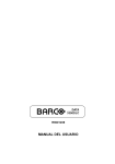


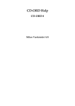

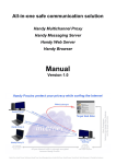


![ZXmore-V11-ConstructionKit [1144.78] KB](http://vs1.manualzilla.com/store/data/005859049_1-e30fafda14586d16f36a324828eeb8d9-150x150.png)