1
10. RECORDER CONFIGURATION.
4. MOUNTING.
Recorder.
After mounting the recorder and all measuring sensors, connect the power supply and configure
the device.
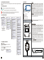
10.1. MENU HANDLER.
- starts menu and parameters edition and accepts changes
- changes the parameters values and passes between them
- backs up one level higher in the menu nad exits from the configuration menu,
it is also used to go back to the previous character edition
Recorder DR-101
10.2. MENU DIAGRAM.
Aggregate relay
When choosing an assembly location you have to remember
that the casing of the recorder is non resistant to difficult
environment conditions. Therefore, it should be mounted in the
vehicle trailer. You have to remember to tighten the cover of the
electrical connectors and wires glands firmly and to close the
casing doors properly.
Before mounting you should mark places for holes accroding to
dimensions (see: Pic.2) or try on the recorder. Then drill holes
with a diameter of 5 mm and tighten with screws or drill holes
with a diameter of 4 mm and tighten screws with a diameter of
4,5 mm. Wires should be led through waterproof glands
separately. Try on use existing raceways for wires assembly. If it
is essential to use separate raceways, you should use selfadhesive ones and where the holes are drilled you have to seal
them with an appropriate substance.
Temperature sensor
1.2 Print to...
30-05-2011 23:59
Printing....
Report printout from
a period of time
and exit from
configuration menu
3.Inputs.
2.1 Alarm function:
On
Off
3.1 Sensor T1:
On
Off
2.2 Minimum
1.3
T1 MIN: T1:
-50°C
-40°C
3.2 Sensor description T1
Temperature sensor 1
2.3 T1 MAX:
120°C
3.3 Calibration T1
0.0°C
2.4 Alarm delay
3 min
3.4 Input D1:
Off
On- NO
On- NC
3.5 Input description D1:
Defrosting
3.6 Input D2:
Off
On - NO
On- NC
Delivery function
3.7 Input description D2:
Delivery
10.3. MEMORY CLEARING.
Attention!
After running this function, all data will be
IRRECOVERABLE!
To delete the data, enter 4.13 parameter, set “YES”
and confirm with
button.
Memory clearing process is signalled by command
on the display:
Data deletion ..
4.Configuration.
4.1 Language :
Polish
English
German
Door opening sensor
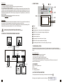
Pic.1 The example of the recording system
in the truck.
4.2 Date,time :
01-05-2011 22:34
125
4.3 Sampling time.
15 min
4.4 User data L1:
4.5 User data L2:
4.6 User data L3:
4.7 Registration number
149
4.8 Backlight
On
Off
Pic.2 Recorder casing dimensions.
4.9 Signalling
Sound on
Sound off
46
Temperature sensors.
Recorder is equipped with one temperature sensor (wired or
casing). Temperature sensor should be mounted in a cold
chamber in a safe place, not exposed where is a proper air
circulation. The source of indoor lighting should not be closer
than 50 cm from the sensors. The recommended location of the
sensors is on the wall 30 cm from the ceiling, properly 1/3 or 2/3
of the chamber length from the outlet of the evaporator.
Wired sensor (Pic.3) is mounted in a vertical position with an
ending upwards, directly on the wall inside the chamber by
means of clamps and fixing chucks.
Casing sensor (Pic.4) is mounted on the wall using screws or
bolts. It should be installed in a vertical position with an ending
upwards. Try on the sensor and mark places for holes before
mounting.Drill the holes with a diameter of 4 mm.Supply
conduct should be connected to stirrup bolts and led through
waterproof gland.
Sensors does not require maintaining wiring polarity. To extend
the sensors use standard OMY wires with a section not less
than 0,75mm2. Maximum wire length should not exceed 100
meters depending on quality and section of used wire.
4.10 Brief printout
Actual measurements
From delivery
From the last hour
From today
4.11 Factory settings
Do not restore
Data restore
4.12 Data delete ?
No
Yes
50
4.13 Password :
000
Ip67 protection class
Pic.3. Casing sensor dimensions.
5
Remember to make sure that all drilled holes are sealed
by aprropriate silicon sealant. .
33
1.1 Print from...
01-05-2011 00:00
2.Alarms.
183
1.Print from selected day
5 or 10m
20
Rys.4 Wymiary czujnika naściennego.
Pic.4. Wiring sensor dimensions.
3