1
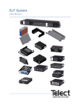
IG700
User’s Installation and
Configuration Manual
Copyright © 2011
This manual is copyrighted, with all rights reserved. Under
the copyright laws, this manual may not, in whole or in part,
be copied, photocopied, reproduced, translated or
converted to any electronic medium or machine readable
form without prior written consent.
Limited Warranty
Under all circumstances this manual should be read
attentively before installing and/or using the product. In no
event shall be liable for any direct, indirect, special,
consequential or incidental damages arising out of the use
or inability to use this documentation or product, even if
advised of the possibility of such damages. In particular,
shall not be liable for any hardware, software, or data that is
stored or used with the product, including the cost of
repairing, replacing or recovering the above. Champtek
reserves the right to change parts of the device at any time
without preceding or direct announcement to the client.
Champtek reserves the right to revise this manual, and to
make changes in the contents without obligation to notify
any person or entity of the revision or change. A serial
number appears on the product. Make sure that this official
registration number has not been removed. It should be
provided whenever servicing by Champtek or an authorized
Champtek dealer.
Notice: The manufacturer shall not be responsible neither
for technical or editorial errors, nor for incidental or
consequential damages due to the connection with the
furnishing, performance, or usage of the publication.
DEC. 2011
Table of Contents
INTRODUCTION .......................................
....................................... 1
CHAPTER 1 PRODUCT SAFETY ............. 1
1.1
Safety & Caution ............................1
1.2
FCC Warning .................................3
1.3
Use of The IG-700 .........................4
1.4
IG-700 Unpacking..........................5
1.5
Mounting ........................................6
1.6
USB Interface ................................7
1.7
Configuration .................................7
1.7.1 Changing Scanner Settings with
Programming Codes..................................7
1.7.2 Changing Scanner Settings with
Utility Tool .................................................. 8
CHAPTER 2 CONFIGURATION ................ 9
2.1
2.2
2.3
2.4
2.5
2.6
2.7
2.8
USB Mode .....................................9
RS232 Mode ............................... 10
Trigger Mode .............................. 11
Symbology Selection .................. 12
Read Version .............................. 21
Language Keyboard Mapping .... 22
Prefix........................................... 23
Suffix ........................................... 23
APPENDIC
APPENDICES.. .......................................
....................................... 25
A. Readable Symbologies ..................... 25
B. Technical Specifications ................... 25
C. Scan Map .......................................... 27
Introduction
IG-700 is a cutting-edge gun-type barcode
scanner which is designed specifically for
retail market. We add on more user-friendly
functions with detachable cable that makes it
more easily to be operated by the customers.
The new IG-700 supports middle to long
range operation. It is absolutely a high
performance gun-type scanner. It provides
the customer with the most efficient solution
in the market. It is perfectly suitable and
definitely the best choice for any retailers
who use POS environment.
Compare with expensive products, IG-700 is
with competitive price, higher quality and
better performance. Due to the high MTBF of
every component, a long operation time is
secured.
The new scanner supports several interface
types. These include RS232, USB HID and
USB virtual com interfaces.
Chapter 1 Product Safety
1.1 SAFETY & CAUTION
1. Please read the following safety
statement carefully.
2. Please preserve this user manual for
reference.
3. Before cleaning the IG-700, the user
must unplug all power. Do not use
liquid or spray type of detergent to
clean the scanner. Please use
dampish cotton cloth to clean the
scanner.
4. The power cord must be set nearby the
scanner for easier power connection.
5. Keep the product dry to avoid short
circuit.
6. During installation, the user must set
the equipment at solid table to avoid
damage caused by falling.
7. Before connecting to power, please
ensure the voltage is pertaining to the
equipment.
8. For safety issue, please tie wire well
and do not put anything on the wire.
9. Please unplug the power after using
the scanner. The over clocking usage
of the product may result the decline
of adapter life. Do not spray any liquid
on this scanner because it may cause
a fire or short circuit.
10. Do not spray any liquid on this
scanner because it may cause a fire or
short circuit.
11. If there are following situations, please
contact the qualified technician to
check this product.
1
(a) The damage of wire or pin of
power supply.
(b) The liquid infiltrates in the
product.
(c) The exposure of the product in
the wet environment.
(d) The equipment cannot work well.
(e) Any obvious damage that causes
the scanner to fail working
normally.
12. Do not storage the scanner in where
the temperature lower than -20°C
(-4°F) or higher than +70°C (158°F).
2
1.2 FCC WARNING
This product complies with the
requirements in Part 15 of FCC.
Any operation must comply with the
conditions below:
(a) The equipment will not cause any
severe interference.
(b) The equipment can avoid any
interference from environment.
Statement:
This product is classified as
an A class product.
This product may cause
some interference with the
environment surrounded; the
user may have to do
something to avoid interference under
this circumstance.
3
1.3 USE OF THE IG-700
IG-700 is very contemporarily designed and
commonly applicable. It can be connected to
POS or Host system through RS232 cable or
USB cable.
To read a bar code, simply press the trigger
button and aim the blue beam at the bar
codes. It is required to position the beam
vertically intersecting with the bar codes. The
user will hear one beep, and the green LED
will light on to confirm a successful scan.
The programming of the scanner is very
easy. The user only needs to scan all
necessary programming codes. The settings
are directly saved permanently, and all
settings can be disabled after scanning the
factory default bar code.
Due to the powerful decoding processor, the
IG-700 can decode almost all major 1D and
2D codes.
4
1.4 IG-700 UNPACKING
Unpack the IG-700 as follows:
1. Take the scanner and its accessories out
of the box.
2. Remove the packing material.
3. Check the packing list to make sure you
receive all of the items ordered.
Standard Shipment Package
(a) IG-700 Area Imager Handheld Bar
code Scanner
(b) Communication Cable
(c) Power Adaptor (optional)
(d) User Manual
4. Check the IG-700 and accessories for
any physical damage.
ATTENTION
The packing box should be
used whenever the IG-700 is
transported for service.
5
1.5 MOUNTING
The new IG-700 is designed for
costumer-installation. Once the user
unpacks all components, he/she can start
installing the scanner.
The following are the steps for installation:
1. Connect the scanner to the supplied
interface cable (RJ45 side).
2. Connect the scanner interface cable to
the POS system.
3. Connect the power supply cable (RS232
interface) to power cable jack.
4. Plug the power supply cable into the AC
outlet.
6
1.6 USB INTERFACE
Like all USB devices, the user must install
the driver on the host system before
connecting the IG-700 with USB virtual com
interface.
Please contact Champtek Technical Support
Department if the user needs the USB driver.
The user can also download the USB driver
from the web site listed below:
http://www.champtek.com/
1.7 CONFIGURATION
How to configure the IG-700:
The barcode programming features the
possibility to change the scanner settings
with the programming codes or with the utility
tool.
1.7.1 Changing Scanner Settings with
Programming Codes
The user can setup scanner by scanning all
necessary programming codes for
parameters that meet applications. The
configuration change will take effect
immediately and save to memory.
To go back to the factory default settings the
user simply scans the factory default bar
code.
7
1.7.2 Changing Scanner Settings with
Utility Tool
Champtek provides this user manual with the
most common used programming codes; it is
possible that the user does not have enough
programming codes to meet his/her desired
operational settings.
This tool can be used with the following
operation systems: Windows98,
Windows2000, Windows XP and Windows
Vista.
This utility tool can be delivered upon
request. Please contact Champtek Technical
Support Department. The USB driver can be
downloaded from the Champtek web site
listed below:
http://www.champtek.com/
8
Chapter 2 Configuration
The configuration change will take effect
immediately and save to memory.
2.1 USB MODE
9
2.2 RS232 MODE
10
2.3 TRIGGER MODE
11
2.4 SYMBOLOGY SELECTION
12
13
14
15
16
17
18
19
20
2.5 READ VERSION
21
2.6 LANGUAGE KEYBOARD MAPPING
22
2.7 PREFIX
2.8 SUFFIX
23
24
Appendices
A.READABLE SYMBOLOGIES
Symbologies
Aztec
Codabar
Codablock
Code 11
Code 39
Code 93
Code 128
Composite
DataMatrix
GS1 DataBar (RSS)
Interleaved 2 of 5
Matrix 2 of 5
MaxiCode
Marco PDF417
Micro PDF417
MSI Plessey
NEC2 of 5
PDF417
Post Codes(Australian, Japan,
KIX, Postnet, Planet, Royal)
QR Code
Telepen
UPC/EAN
Default
Enable
V
V
V
V
V
V
V
V
V
V
V
V
B.TECHNICAL SPECIFICATIONS
Physical Characteristics
Body Weight
Approx. 150 gm
Material
ABS Plastic
Connector
RJ45C 10Pins
Dimension
82.85(L)x 75(W) x 171.3(H)mm
25
Operational
Light Source
Resolution
Scan Angle
Visible Red Light 650nm + 20nm
1280 Horizontal x 960 Vertical
Pixels, 256 Gray Levels.
30° Horizontal, 20° Vertical on high
density field
50° Horizontal, 33.5° Vertical on
wide field
Pitch
Skew
Rotational
Tolerance
Interface
Indicators
±60° (from front to back)
±60° (from plane parallel to
symbol(side- to-side)
±180°
RS-232, USB (HID KBW or Virtual
Comport)
Green = good read
Electrical Characteristics
Operation
Voltage
Operating
Current
Standby
Current
AC Adaptor
5 VDC ±5%
450 mA (max) @ 5 VDC
37 mA typical @ 5 VDC
5.2 VDC @ 650 mA / Input AC
100-240V
26
Environmental
Operating
Temp.
0°C to 50°C (32°F to 122°F)
Storage Temp. -20°C to 70°C (-4°F to 158°F)
Relative
Humidity
0 to 95% non-condensing
Ambient Light
Work in lighting conditions from 0 to
100,000 lux
Regulatory of Compliance
FCC
CE
C.SCAN MAP
Typical Reading Range (Centimeters)
Symbology Density Minimum Maximum
Distance
Distance
Inches(mm) Inches(mm)
Code 39
3mil
3.9"(100)
4.7"(120)
7.5mil
2.0"(50)
8.0"(205)
13mil
2.0"(50)
10.8"(275)
Data Matrix 4.2mil
3.7"(9.5)
4.7"(120)
5mil
3.7"(9.5)
5.5"(140)
6.3mil
3.3"(85)
6.3"(160)
10mil
1.6"(40)
7.9"(200)
20.8mil
1.6"(40)
12.2"(310)
UPC
27
28