1
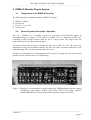
OPERATING INSTRUCTIONS AND
SYSTEM DESCRIPTION FOR THE
INT-03M / INT-04M / INT-20M
BREAKOUT BOX MODULES
FOR EPMS SYSTEMS
VERSION 1.0
npi 2008
npi electronic GmbH, Hauptstrasse 96, D-71732 Tamm, Germany
Phone +49 (0)7141-9730230; Fax: +49 (0)7141-9730240
[email protected]; http://www.npielectronic.com
INT-03M / INT-04M / INT-20M User Manual
_________________________________________________________________________________________________________________________________
Table of Contents
1. Safety Regulations .............................................................................................................. 3
2. EPMS-07 Modular Plug-In System .................................................................................... 4
2.1. Components of the EPMS-07 Housing ....................................................................... 4
2.2. General System Description / Operation ..................................................................... 4
2.3. System Grounding ....................................................................................................... 5
2.4. Technical Data............................................................................................................. 5
3. Breakout Box Module System............................................................................................ 6
3.1. Components ................................................................................................................. 6
3.2. System Description...................................................................................................... 6
INT-03M...................................................................................................................... 6
INT-04M...................................................................................................................... 8
INT-20M...................................................................................................................... 9
4. Connections ........................................................................................................................ 10
___________________________________________________________________________
version 1.5
page 2
INT-03M / INT-04M / INT-20M User Manual
_________________________________________________________________________________________________________________________________
1. Safety Regulations
VERY IMPORTANT: Instruments and components supplied by npi electronic are NOT
intended for clinical use or medical purposes (e.g. for diagnosis or treatment of humans),
or for any other life-supporting system. npi electronic disclaims any warranties for such
purpose. Equipment supplied by npi electronic must be operated only by selected,
trained and adequately instructed personnel. For details please consult the GENERAL
TERMS OF DELIVERY AND CONDITIONS OF BUSINESS of npi electronic, D-71732
Tamm, Germany.
1)
GENERAL: This system is designed for use in scientific laboratories and must be
operated only by trained staff. General safety regulations for operating electrical devices
should be followed.
2)
AC MAINS CONNECTION: While working with the npi systems, always adhere to the
appropriate safety measures for handling electronic devices. Before using any device
please read manuals and instructions carefully.
The device is to be operated only at 115/230 Volt 60/50 Hz AC. Please check for
appropriate line voltage before connecting any system to mains.
Always use a three-wire line cord and a mains power-plug with a protection contact
connected to ground (protective earth).
Before opening the cabinet, unplug the instrument.
Unplug the instrument when replacing the fuse or changing line voltage. Replace fuse
only with an appropriate specified type.
3)
STATIC ELECTRICITY: Electronic equipment is sensitive to static discharges. Some
devices such as sensor inputs are equipped with very sensitive FET amplifiers, which can
be damaged by electrostatic charge and must therefore be handled with care. Electrostatic
discharge can be avoided by touching a grounded metal surface when changing or
adjusting sensors. Always turn power off when adding or removing modules,
connecting or disconnecting sensors, headstages or other components from the
instrument or 19” cabinet.
4)
TEMPERATURE DRIFT / WARM-UP TIME: All analog electronic systems are
sensitive to temperature changes. Therefore, all electronic instruments containing analog
circuits should be used only in a warmed-up condition (i.e. after internal temperature has
reached steady-state values). In most cases a warm-up period of 20-30 minutes is
sufficient.
5)
HANDLING: Please protect the device from moisture, heat, radiation and corrosive
chemicals.
6)
I/O BOARDS: This breakout box can be used only with computer boards from National
Instruments. These I/O boards must be installed and configured first. For the correct
installation and configuration read the user manual of the appropriate board (shipped
with the board).
7)
VERY IMPORTANT: Always turn power off when connecting or disconnecting
components at the rear panel of the breakout box to avoid any damage.
___________________________________________________________________________
version 1.5
page 3
INT-03M / INT-04M / INT-20M User Manual
_________________________________________________________________________________________________________________________________
2. EPMS-07 Modular Plug-In System
2.1.
Components of the EPMS-07 Housing
The following items are shipped with the EPMS-07 housing:
EPMS-07 cabinet
Power cord
Fuse 0.8 / 0.4A, slow
Front covers
2.2.
General System Description / Operation
The npi – EPMS-07 is a modular system for processing of bioelectrical signals in
electrophysiology (see Figure 1). The system is housed in a 19” rackmount cabinet (3U)
containing a power supply and has room for up to 7 plug-in units. The plug-in units are
connected to power by a bus at the rear panel.
The plug-in units must be kept in position by four screws (M 2,5 x 10). The screws are
important not only for mechanical stability but also for proper electrical connection to the
system housing. Free area must be protected with covers.
In order to avoid induction of electromagnetic noise the power supply unit, the power-switch
and the fuse are located at the rear of the housing.
Figure 1: Example of a measurement system located in an EPMS housing with two channel
iontophoresis and balance module (MVCS-02, MVCC-02), bridge amplifier
module (BRAMP-01R) and an extracellular amplifier module (EXT-01C)
___________________________________________________________________________
version 1.5
page 4
INT-03M / INT-04M / INT-20M User Manual
_________________________________________________________________________________________________________________________________
2.3.
System Grounding
The 19" cabinet is grounded by the power cable through the ground pin of the mains
connector (= protective earth). In order to avoid ground loops the internal ground is isolated
from the protective earth. The internal ground is used on the BNC connectors or GROUND
plugs of the modules that are inserted into the EPMS-07 housing. The internal ground and
mains ground (= protective earth) can be connected by a wire using the ground plugs on the
rear panel of the instrument. It is not possible to predict whether measurements will be less or
more noisy with the internal ground and mains ground connected. We recommend that you try
both arrangements to determine the best configuration.
2.4.
Technical Data
- 19” rackmount cabinet, 3U high (1U=1 3/4” = 44.45 mm), for up to 7 plug-in units
- Power supply: 115/230 Volts AC, 60/50 Hz, fuse 0.8/0.4 A slow, 45-60 W
___________________________________________________________________________
version 1.5
page 5
INT-03M / INT-04M / INT-20M User Manual
_________________________________________________________________________________________________________________________________
3. Breakout Box Module System
3.1.
Components
The following items are shipped with the INT-03M:
Two INT-03M modules
Two modified INT-20M modules
One INT-04M module
User manual
3.2.
System Description
The system connects two Tucker-Davis headstages to two PCI-6341 multifunction I/O boards
from National Instruments. The system consist of two INT-03M, one INT-04M module and
two modified INT-20M modules. These are used in conjunction with 16 DPA-2FL modules
and a separate stimulus isolator.
INT-03M
Eight switches allow each input channel to function as reference or as measuring channel.
Three 25-pole SUBD connectors are used for connection to other EPMS housings in the
system, and stimuli from two stimulus isolators can be connected by four banana jacks.
Description of the Front Panel
Figure 2: INT-03M front panel view
___________________________________________________________________________
version 1.5
page 6
INT-03M / INT-04M / INT-20M User Manual
_________________________________________________________________________________________________________________________________
In the following description of the front panel elements each element has a number that is
related to that in Figure 2. The number is followed by the name (in uppercase letters) written
on the front panel and the type of the element (in lowercase letters). Then, a short description
of the element is given.
(1) Channel type selectors
Switches for selecting the operation mode of the respective channel, e.g. for channel 0
CH 0: Channel 0 operates as measuring channel
REF: Channel 0 operates as reference channel
(2) Headstage connector PREAMP
25-pole SUBD connector for the PREAMP line of the headstage
(3) Headstage connector CONTROL
25-pole SUBD connector for the CONTROL line of the headstage (only in H-Rec-Stim
headstage)
(4) Headstage connector STIMULATOR
25-pole SUBD connector for the STIMULATOR line of the headstage (only in H-Rec-Stim
headstage)
(5) ISO STIM INPUT connectors
Connectors for the stimulus signals from maximum two stimulus isolators (only in H-RecStim headstage).
The headstages suitable for this systems are different. One headstage (H-Rec) is only for
recording, the other headstage (H-Rec-Stim) is for recording and stimulation. Therefore,
connectors (3) and (4) are available only for the H-Rec-Stim headstage.
___________________________________________________________________________
version 1.5
page 7
INT-03M / INT-04M / INT-20M User Manual
_________________________________________________________________________________________________________________________________
INT-04M
The INT-04M breakout box serves as distribution module for signals coming from and going
to DPA-2FL amplifier modules. It collects the signals from the three EPMS housings and
passes them to the modified INT-20M modules.
Description of the Front Panel
Figure 3: INT-04M front panel view
(1) BUS SIGNAL CONNECTOR #1
25-pole SUBD connector for the from and to EPMS #1
(2) SIGNAL BREAKOUT
For internal use only
(3) BUS SIGNAL CONNECTOR #2
25-pole SUBD connector for the from and to EPMS #2
The INT-04M breakout box is connected to the INT-20M modules with two 25/9 pole cables.
___________________________________________________________________________
version 1.5
page 8
INT-03M / INT-04M / INT-20M User Manual
_________________________________________________________________________________________________________________________________
INT-20M
The modified INT-20M breakout box serves as distribution module for signals coming from
and going to DPA-2FL amplifier modules. It collects the signals from the three EPMS
housings and passes them to the data acquisition board from National Instruments. It also
allows connection of the digital I/O lines of the PCI-6143.
Description of the Front Panel
Figure 4: modified INT-20M breakout box front panel view
(1) CONNECTED LED
LED indicating that a data acquisition board is connected properly.
(2) POWER LED
LED indicating that a the EPMS-07 system is powered on.
(3) TRIG LED
Not installed
(4) MAN TRIG switch
Not installed
___________________________________________________________________________
version 1.5
page 9
INT-03M / INT-04M / INT-20M User Manual
_________________________________________________________________________________________________________________________________
(5) Ao0 connector
BNC connector for digital line 6 from the data acquisition board.
(6) TRIG IN connector
BNC connector for digital line 4 from the data acquisition board.
(7) Ao1 connector
BNC connector for digital line 7 from the data acquisition board.
(8) TRIG OUT connector
BNC connector for digital line 5 from the data acquisition board.
(9) Ai8…Ai15 connector
SUBD 9-pole female connector for connecting EPMS #2 to EPMS #1 and EPMS #3,
respectively.
(10) POWER OUTPUT connector
SUBD 9-pole female connector for digital lines 0 to 7.
(11) TO COMPUTER connector
SCSI 68-pole female connector for connecting the data acquisition board from National
Instruments.
4. Connections
The connections of the system are illustrated in Figure 5.
The recorded signals from the headstages are collected by the INT-03M modules and passed
to the DPA-2FL modules for amplification and filtering. Reference and recording electrodes
are defined by the INT-03M modules as well. The processed signals are linked to the two
PCI-6143 boards using the INT-04M module and two modified INT-20M modules.
The outputs of one or two stimulus isolators can be connected to the INT-03M modules of
EPMS #1 for stimulation. These signals are linked to the H-Rec-Stim headstage. The
electrodes are switched between recording and stimulation by software through signals
connected to CONTROL connector of the INT-03M in EPMS #1.
___________________________________________________________________________
version 1.5
page 10
INT-03M / INT-04M / INT-20M User Manual
_________________________________________________________________________________________________________________________________
Figure 5: connection scheme
___________________________________________________________________________
version 1.5
page 11