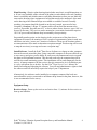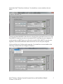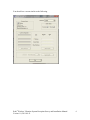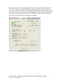
1
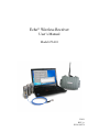
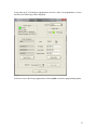
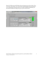
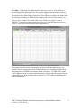
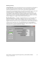
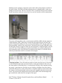
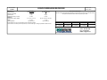
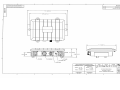
Model 673A01
Echo® Wireless Receiver
Installation and Operating Manual
For assistance with the operation of this product,
contact PCB Piezotronics, Inc.
Toll-free: 800-959-4464
24-hour SensorLine: 716-684-0001
Fax: 716-684-3823
E-mail: [email protected]
Web: www.imi-sensors.com
Warranty, Service, Repair, and
Return Policies and Instructions
The information contained in this document supersedes all similar information that
may be found elsewhere in this manual.
Total Customer Satisfaction – PCB
Piezotronics guarantees Total Customer
Satisfaction. If, at any time, for any
reason, you are not completely satisfied
with any PCB product, PCB will repair,
replace, or exchange it at no charge. You
may also choose to have your purchase
price refunded in lieu of the repair,
replacement, or exchange of the product.
Service – Due to the sophisticated nature
of the sensors and associated
instrumentation provided by PCB
Piezotronics, user servicing or repair is
not recommended and, if attempted, may
void the factory warranty. Routine
maintenance, such as the cleaning of
electrical connectors, housings, and
mounting surfaces with solutions and
techniques that will not harm the
physical material of construction, is
acceptable. Caution should be observed
to insure that liquids are not permitted to
migrate into devices that are not
hermetically sealed. Such devices should
only be wiped with a dampened cloth
and never submerged or have liquids
poured upon them.
Repair – In the event that equipment
becomes damaged or ceases to operate,
arrangements should be made to return
the equipment to PCB Piezotronics for
repair. User servicing or repair is not
recommended and, if attempted, may
void the factory warranty.
Calibration – Routine calibration of
sensors and associated instrumentation is
recommended as this helps build
confidence in measurement accuracy and
acquired data. Equipment calibration
cycles are typically established by the
users own quality regimen. When in
doubt about a calibration cycle, a good
“rule of thumb” is to recalibrate on an
annual basis. It is also good practice to
recalibrate after exposure to any severe
temperature extreme, shock, load, or
other environmental influence, or prior
to any critical test.
PCB Piezotronics maintains an ISO9001 certified metrology laboratory and
offers calibration services, which are
accredited by A2LA to ISO/IEC 17025,
with full traceablility to N.I.S.T. In
addition to the normally supplied
calibration, special testing is also
available, such as: sensitivity at elevated
or cryogenic temperatures, phase
response, extended high or low
frequency response, extended range, leak
testing, hydrostatic pressure testing, and
others. For information on standard
recalibration services or special testing,
contact your local PCB Piezotronics
distributor, sales representative, or
factory customer service representative.
Returning Equipment – Following
these procedures will insure that your
returned materials are handled in the
most expedient manner. Before returning
any equipment to PCB Piezotronics,
contact your local distributor, sales
representative, or factory customer
service representative to obtain a Return
Materials
Authorization
(RMA)
Number. This RMA number should be
clearly marked on the outside of all
package(s) and on the packing list(s)
accompanying the shipment. A detailed
account of the nature of the problem(s)
being experienced with the equipment
should also be included inside the
package(s) containing any returned
materials.
PCB for a complete statement of our
warranty. Expendable items, such as
batteries and mounting hardware, are not
covered by warranty. Mechanical
damage to equipment due to improper
use is not covered by warranty.
Electronic circuitry failure caused by the
introduction of unregulated or improper
excitation power or electrostatic
discharge is not covered by warranty.
A Purchase Order, included with the
returned materials, will expedite the
turn-around of serviced equipment. It is
recommended to include authorization
on the Purchase Order for PCB to
proceed with any repairs, as long as they
do not exceed 50% of the replacement
cost of the returned item(s). PCB will
provide a price quotation or replacement
recommendation for any item whose
repair costs would exceed 50% of
replacement cost, or any item that is not
economically feasible to repair. For
routine calibration services, the Purchase
Order should include authorization to
proceed and return at current pricing,
which can be obtained from a factory
customer service representative.
Contact Information – International
customers should direct all inquiries to
their local distributor or sales office. A
complete list of distributors and offices
can be found at www.pcb.com.
Customers within the United States may
contact their local sales representative or
a
factory
customer
service
representative. A complete list of sales
representatives can be found at
www.pcb.com. Toll-free telephone
numbers for a factory customer service
representative,
in
the
division
responsible for this product, can be
found on the title page at the front of this
manual. Our ship to address and general
contact numbers are:
Warranty – All equipment and repair
services provided by PCB Piezotronics,
Inc. are covered by a limited warranty
against
defective
material
and
workmanship for a period of one year
from date of original purchase. Contact
DOCUMENT NUMBER: 21354
DOCUMENT REVISION: B
ECN: 17900
PCB Piezotronics, Inc.
3425 Walden Ave.
Depew, NY 14043 USA
Toll-free: (800) 828-8840
24-hour SensorLineSM: (716) 684-0001
Website: www.pcb.com
E-mail: [email protected]
Echo® Wireless Receiver
User’s Manual
Model 673A01
52439
REV. A
ECN#: 40574
Table of Contents
FCC NOTICE ..................................................................................................................... 3
FCC ID: ZOC-IMI673A01 ............................................................................................. 3
INDUSTRY CANADA (IC) NOTICE............................................................................... 3
IC: 9732A-IMI673A01 ................................................................................................... 3
Introduction......................................................................................................................... 4
Proper Handling .................................................................................................................. 4
Receiver Connections ......................................................................................................... 5
Connection A – MIL Connector ..................................................................................... 6
Connection B – Waterproof Ethernet ............................................................................. 6
Connection C – N Antenna Connection.......................................................................... 6
Locating and Installing the Receiver .................................................................................. 7
Programming the Receiver ................................................................................................. 8
Setting a Static or Dynamic IP Address.......................................................................... 8
2
FCC NOTICE
FCC ID: ZOC-IMI673A01
This device complies with part 15 of the FCC Rules. Operation is subject to the following
two conditions: (1) This device may not cause harmful interference, and (2) this device
must accept any interference received, including interference that may cause undesired
operation.
Changes or modifications not expressly approved by the party responsible for compliance
could void the user's authority to operate the equipment.
This equipment has been tested and found to comply with the limits for a Class A digital
device, pursuant to part 15 of the FCC Rules. These limits are designed to provide
reasonable protection against harmful interference when the equipment is operated in a
commercial environment. This equipment generates, uses, and can radiate radio
frequency energy and, if not installed and used in accordance with the instruction manual,
may cause harmful interference to radio communications. Operation of this equipment in
a residential area is likely to cause harmful interference in which case the user will be
required to correct the interference at his own expense.
INDUSTRY CANADA (IC) NOTICE
IC: 9732A-IMI673A01
Operation is subject to the following two conditions: (1) this device may not cause
interference, and (2) this device must accept any interference, including interference that
may cause undesired operation of the device.
3
Introduction
The Echo® Receiver is a one-way wireless communication receiver operating in the 902928 MHz unlicensed ISM Band. Using exclusive Extended Range RF technology, it
receives wirelessly transmitted vibration data from Echo® Wireless Vibration Sensors and
EchoPlus® Wireless Junction Boxes. It outputs the data to a computer or server running
Echo® Monitoring Software through a standard Ethernet connection. The data is stored in
a Microsoft® SQL database and can be displayed with the Echo® Data Presentation
portion of the Echo® Monitoring software. For details on system and software installation,
see the Echo® Wireless Vibration System Reception Survey and Installation Manual and
the Echo® Monitoring Software User’s Manual.
Proper Handling
Proper handling and location of the Echo® Receiver is critical to correct operation and
preventing damage. The box is rated at MIL-STD-810, Method 506.4 Procedure I and
MIL-STD-810, Method 510.4 Procedures I and II. While it can be used in areas where
there is some contact with water and the elements, it is not recommended that it be placed
in an area where it will be subjected to heavy sprays or harsh weather. The receiver has
an operating temperature range of -25° to +120° F (-32° to +49° C). Exposure to
temperatures outside of this range may result in incorrect operation. It has a storage
temperature range of -28° to +160° F (-33° to +71° C). Exposure to temperatures outside
this range may result in damage to the electronic circuits.
Warning: Do not attempt to remove the cover of the Echo® Receiver. There are no
customer serviceable components inside. Removing the cover will void the warranty.
4
Receiver Connections
The Echo® Receiver is has 4 connectors and an LED mounted on the side of the unit, see
photo below. There are two identical and interchangeable MIL style bayonet connectors
for power and RS-232 (serial cable), one RJ-45 Waterproof Ethernet connector, and 1 Nfemale antenna connector. Labels for these connectors are found on the bottom of the
receiver.
Note: The MIL connectors can be used interchangeably for power or RS-232 serial
interface.
Note: The receiver requires an optional Model 009M201 Echo® Receiver Serial Cable to
use the serial port on the receiver.
Note: In order to be waterproof, a waterproof Ethernet cable with screw on connector
must be used.
Location
A
Connector Type
MIL
B
RF-45, Waterproof
Ethernet
N-female
C
A
B
Function
Power Cable or
Serial Cable
Network Cable
Quantity
2
Antenna
1
C
1
A
5
Connection A – MIL Connector
The use of the MIL connectors is completely interchangeable between power and the
serial interface. These connectors are used for two purposes. The first is for powering the
Receiver. The supplied power adaptor has a mating MIL connector. The power adapter
requires 100 to 240 VAC, 47 – 63 Hz line power. It provides the receiver with 12VDC
power. When power is connected to the receiver, the blue LED will illuminate indicating
the unit is on.
Warning: Do not apply line power directly to the receiver. Damage to the unit will occur.
Caution: It is not recommended to use a different 12 VDC power source than the
supplied adaptor. If you intend to use a 12 VDC power supply other than the one supplied,
contact IMI for important information.
The MIL connectors on the receiver are also used for programming and updating the
Echo® Receiver. An optional Model 009M201 Echo® Receiver Serial Cable (RS232 to
MIL connector) is required to connect the receiver to a computer. For specific
information on how to program or update the receiver, consult the “Programming the
Receiver” section of this manual.
Connection B – Waterproof Ethernet
The Ethernet connector is used to connect the receiver to a network or stand alone
computer. Any standard Ethernet cable (not provided) can be used to connect the receiver
to a network. However, an industrial grade waterproof Ethernet connector may also be
used and may be a better choice for dirty industrial environments because the boot will
provide some additional protection.
Note: If you choose to connect the receiver output directly into a stand alone computer a
crossover cable is recommend in place of a standard Ethernet cable.
Connection C – N Antenna Connection
The N connector is used for the antenna input. A small antenna with appropriate adaptors
is supplied with the receiver. This antenna will allow you to conveniently get started with
the system, run some tests, and check things out. Most applications, however, will require
a higher gain antenna (not supplied) connected to the receiver with a low loss antenna
cable (not supplied). For specific instructions on selecting, locating, and mounting a
remote antenna, please refer to the Echo® Wireless Vibration System Reception Survey
and Installation Manual.
Note: It is recommended that a low loss antenna cable (-4 dB loss / 100 ft) be used with
an external higher gain antenna.
6
Locating and Installing the Receiver
The receiver must be located a near line power source and an Ethernet network
connection. The antenna should be located centrally to the area of interest and up high.
Typically, a 6dBi gain omnidirectional antenna (not provided) is a good choice, although
circumstances may suggest something different, like a Yagi directional antenna. Use low
loss antenna cable and keep the length as short as possible, typically less than 100 feet.
A good strategy is to map out your facility and mark possible locations for the receiver(s).
Based on the possible receiver locations and the required measurement point locations,
run a reception survey in the plant to determine the optimal location(s) for the receiver(s).
For detailed information on this process, see the Echo® Wireless Vibration System
Reception Survey and Installation Manual.
The receiver is included with mounting hardware that can be used to secure it in place.
The receiver should be physically located where it can be accessed with the programming
cable should settings need to be adjusted.
You may use the short antenna provided with the receiver for testing, setup, and in cases
were the sensors are close to the receiver. To improve the performance, a 6 dBi gain
omnidirectional antenna is generally recommended. It should be mounted in an elevated
location for the best performance. In some cases, use either a higher gain omnidirectional
antenna (generally not to exceed 8 dBi) or a higher gain directional Yagi antenna. The
antenna should be connected to the receiver using low loss antenna (-4 dB loss / 100 ft)
7
cable. For specific information consult the Echo® Wireless Vibration System Reception
Survey and Installation Manual.
Note: Proper location of the antenna can make a dramatic difference in system
performance. Care should be given to determining the optimal locations for the receiver
and antenna.
Programming the Receiver
The receiver can be programmed to a static or dynamic IP address and one of 12
independent RF frequency bands. Firmware updates can also be installed when available.
The following equipment is required for programming the receiver:
•
•
•
•
Echo® Receiver
Power supply
Receiver programming cable
Computer with the Echo® Monitoring Software installed
Setting a Static or Dynamic IP Address
To check the status of the IP configuration, launch the Echo® Monitoring Software, click
on Receiver Utilities, and then click Configure IP Address.
Select the COM port the receiver programming cable is connected to.
8
To check the current settings in the receiver, click the Query Receiver button. A screen
similar to the following will be displayed.
9
If the receiver is set to a Static IP address and you require dynamic addressing, click the
Dynamic IP button then click Apply Update as shown below.
10
It is highly recommended to use the receiver with a static IP address. To do this, you will
most likely need the assistance of your IT department. Enter the IP Address, Subnet
Mask, and Default Gateway into the appropriate field as shown below, and then click on
Apply Update.
11
It may take up to 30 seconds to reprogram the receiver. After it is programmed, a screen
similar to the following will be displayed.
After the receiver has been programmed, click on Quit to close the programming menu.
12
Echo® Wireless Vibration System Reception
Survey and Installation Manual
Table of Contents
Introduction………………………………………….……………………………..……..3
Reception Survey Preparation……………………………………………….……………3
Antenna Location…………………………………………………………………………3
Sensors per Receiver………………………………………………………………………3
Plant Drawing……………………………………………………………………………..4
Install Software……………………………………………………………………………4
Equipment Setup……………………………………………………………….………….4
Receiver Setup…………………………………………………………………………….4
Live Data……………………………………………………………………….……..…..9
Running the Survey…………………………………………………………………..…..10
Antenna Placement…………………………..…………………………………….…….10
Baseline Measurement………………..………………………………………….………10
Collecting the Data………………………………………………………………………11
Permanent Installation…………………………………………………….……………..12
Antenna and Receiver……………………………………………………………………12
Echo® Sensors……………………………………………………………………...…….12
EchoPlus® Junction Boxes………………………………………………………...……..12
Echo® Data Server Software……………………………………………..………………13
Echo® Wireless Vibration System Reception Survey and Installation Manual
Version 1.0, 2011-09-21
2
Introduction
The Echo® Wireless Vibration System is used for unattended predictive maintenance and
condition monitoring of plant equipment. Echo® Wireless Vibration Sensors and
EchoPlus® Wireless Junction Boxes wake up periodically and transmit vibration data
wirelessly to one or more Echo® Receivers that are connected to a network or directly to a
computer. Vibration data are automatically compared against alarm values, machinery
status displayed in an alarm panel, and alarm notifications sent vial email if desired. The
data can be viewed, reported, and trended using the Echo® Data Server Software. This
manual is intended to assist users with the initial installation of the Echo® Wireless
Vibration System, including the determination of optimum antenna/receiver placement,
and running a plant wireless reception survey. Specific instructions for setting up Echo®
Wireless Vibration Sensors, EchoPlus® Wireless Junction Boxes, and Echo® Receivers
can be found in their respective manuals.
Reception Survey Preparation
Antenna Location - Prior to installing the Echo® Wireless Vibration System, it is highly
recommended that a wireless reception survey be run in your plant. This will help
determine what coverage can be achieved in your plant and whether or not it can be
covered with a single antenna and receiver. The distance between transmitters and
receivers (sensors and junction boxes are transmitters) varies widely depending on the
infrastructure in the plant. Typically, a 1000 to 2500 foot reception radius can be
achieved although distances can be as low as 250 to 300 feet (e.g., through concrete walls)
and as high as 1 to 2 miles in open areas, although these distances are less common.
Since reception distance is specified as a radius from the antenna location, a central
location will normally work better than corner location in a plant. If more than one
antenna and receiver are used, locations can be distributed to give the best coverage. The
Echo® System transmits and receives point-to-point; no repeaters, bridges, routers,
gateways, nodes, or other intervening network devices are required.
Sensors per Receiver - The factory default transmission interval (i.e., the time between
measurements) for Echo® Sensors and EchoPlus® Junction Boxes is 8-hours or 3 times
per day. At this collection interval, it is recommended that the number of sensors or
channels be limited to 400 per receiver. This is based on a statistical analysis where
transmitters are started in an “intelligent” manner (i.e., staggered), taking into account
clock drift, and assuming no more than a 1% collision rate. That means that no more than
1% of the transmissions may be lost due to too many simultaneous transmissions.
Depending on the plant conditions, this number could be better. If either more than 400
channels or more than 3 measurements are required per day, multiple receivers can be
used. Keep in mind that 3 measurements per day is 90 measurements per month, which is
about 90 times more often than most walk around PM programs. Sensors, junction boxes,
and receivers have 12 programmable RF Bands. For a 5% collision rate, up to 2000
sensors can be assigned per receiver.
Echo® Wireless Vibration System Reception Survey and Installation Manual
Version 1.0, 2011-09-21
3
Plant Drawing - Obtain a plant drawing that includes some basic overall dimensions on
it. If one is not available, make a sketch of the plant (a crude sketch will work if nothing
better is available) and include some overall plant dimensions as best you can. Mark the
areas on the drawing where equipment is located that needs to be monitored. Also mark
on the drawing where Ethernet drops are available or could be located. Generally
speaking, the antenna should be located in an elevated, central, open area for best
reception. A low loss (1 dB per 25’) antenna cable will run from the antenna to the
receiver. If possible, keep this run to 25’ or less to reduce losses, however, up to 100’ can
be used if necessary. The receiver can be mounted at a convenient location but requires
120 VAC power and an Ethernet drop in reasonably close proximity.
Sequentially number points on the drawing in the various areas of the plant where
equipment is located to be monitored. Pick a couple of representative points in each area
and select one in the “worse case” location of each area. These are the locations where a
test transmission will be made to determine reception strength. This drawing will be used
to map the receiver(s) coverage and create a reception map.
Install Software - Install the Echo® Data Server Software on a laptop or other computer
that can be moved around the plant. Using a moveable computer is the most efficient way
to run a survey and gives you the ability to easily move the antenna and receiver around
the plant to find optimum locations. This does not need to be the computer that will be
used for the actual monitoring system. This installation will be used temporarily for the
survey. A laptop computer with the receiver directly connected to it via its Ethernet port
is a very convenient way to do this. See the Echo® Data Server User’s Manual for
details on loading and operating the software. You will need administrative rights to load
the software and will most likely require the help of your IT department.
Alternatively, the software can be installed on a computer connected the local area
network and the receiver connected to an Ethernet drop located in the plant, however, this
is not recommended for the survey.
Equipment Setup
Receiver Setup - Power up the receiver and wait at least 1 ½ minutes for the receiver to
boot up and initialize.
Echo® Wireless Vibration System Reception Survey and Installation Manual
Version 1.0, 2011-09-21
4
Launch the Echo® Data Server Software. You should see a screen similar to the one
below.
Connect the Model 009M201 Echo® Receiver Serial Cable (optional) between one of the
Power/RS232 connectors on the receiver and an RS232 serial port on your computer. If
you do not have an RS232 port you will need to install a USB to RS232 converter (not
supplied). Also install an Ethernet cable between the receiver and your computer.
Click on the Receiver Utilities on the menu bar. You should see a screen similar to the
following, and then click on Configure IP Address.
Echo® Wireless Vibration System Reception Survey and Installation Manual
Version 1.0, 2011-09-21
5
You should see a screen similar to the following.
Echo® Wireless Vibration System Reception Survey and Installation Manual
Version 1.0, 2011-09-21
6
Select the correct Serial Port using the pull down box in the upper right hand corner of
the screen. The Receiver Status Running box should change colors to green when the
correct port is selected. The Current Configuration box should get filled in similar to that
shown in the screen below. If the Current Configuration box does not fill in, then click on
the Query Receiver button. Make a note of the IP address in the Current Configuration
box. This is 169.254.100.100 in the sample screen below.
Echo® Wireless Vibration System Reception Survey and Installation Manual
Version 1.0, 2011-09-21
7
Enter the IP Address into the IP Address box on the main screen as shown below. Then
click on the Connect button. The Connect button should illuminate green and change to
Active indicating the connection has been successfully established. Additionally, the
horizontal bar should also change from grey to green as shown below.
Echo® Wireless Vibration System Reception Survey and Installation Manual
Version 1.0, 2011-09-21
8
Live Data - Click on the Live Data button for the active receiver. You should see a
screen similar to the following. Note, the columns displayed and the display order are
user selectable. To adjust the columns, click on Configuration on the main screen menu
bar and then select Data Display Preferences. This will open a window that allows both
the selection of columns to display and the display order. See the Echo® Data Server
Software User’s Manual for details. This screen will show any Echo® sensor or
EchoPlus® junction box transmissions that are set to the same RF Band as the active
receiver. This screen will be used for the reception survey.
In the upper left hand corner of the display is a Noise value that updates every few
seconds. This the ongoing noise floor of the RF band we are working in. Under ideal
background noise condition, this number should reach about -155 dBm. If the actual
value is higher, then the systems maximum dynamic range is reduced somewhat but the
system still works. In the example above, the Noise is -154.7 dBm so the background
noise is a minimum.
Echo® Wireless Vibration System Reception Survey and Installation Manual
Version 1.0, 2011-09-21
9
Running the Survey
Antenna Placement - Move the computer and receiver to the location to the first place in
the plant that has been selected for the antenna. Use the antenna that is intended for
permanent installation for the test. Do not use the small antenna supplied with the
receiver unless the transmission distances are small and you intend to use it in your actual
installation. In general, a 6 dBi gain antenna with a 10 to 25’ low loss cable is
recommended for most installations, although an 8 dBi gain antenna may also be used.
Contact IMI for additional information regarding antenna options. Connect the antenna
cable between the receiver and antenna and temporarily place the antenna in an elevated
location. Draping it over a pipe or beam will work well for this test.
Baseline Measurement - It is highly recommended that the survey be run with a stand
alone Echo® Wireless Vibration Sensor. Although it can be run with an EchoPlus®
Wireless Junction Box, it will be a bit more difficult and time consuming. It will also be
helpful if the sensor used for the survey is reprogrammed for a short transmission interval
as shown in the screen below. Note: The transmission interval is programmable in 4
second increments. For details on programming Echo® sensors, see the Echo® Wireless
Vibration Sensor Installation and Operation Manual.
Echo® Wireless Vibration System Reception Survey and Installation Manual
Version 1.0, 2011-09-21
10
Standing near the computer, activate the sensor with a fairly strong magnet as shown in
the picture below. The LED will blink indicating that it is changing states, in this case,
turning on. See the Echo® Wireless Vibration Sensor Installation and Operation Manual.
Set the sensor down and move away from it so you don’t interfere with its transmission.
The sensor will immediately make a measurement (solid blue LED) and then transmit it
(solid bright blue LED). About three seconds after the bright LED goes off and if the
system is setup and working correctly, an entry should appear on the top line of the Live
Data spreadsheet, similar to the screen below. Write down the Average SNR (dB) value
for that point. Record a couple of values for each point taken. Using the magnet, turn the
sensor off. Note: If the LED has 4 seconds between blinks, it is on and waiting for the
next transmission time. If the LED has 8-seconds between blinks, it is off and will not
make any measurements until it is activated with a magnet.
Collecting the Data - You will need two people to do the rest of the survey. One person
to walk around the plant and activate the sensor at each point included in the survey in
the same manner as described above. A second person will stay at the computer and log
the results. A good process is for this is to use a radio or cell phone. In a noisy plant, a
method that has proven to work well (if there is cell phone signal) is for the person with
the sensor to text the point number to the person at the computer when they activate the
sensor. The person at the computer then texts back the SNR, which acknowledges they
got it and lets the walker know the strength of the signal.
Echo® Wireless Vibration System Reception Survey and Installation Manual
Version 1.0, 2011-09-21
11
The person viewing the Live Data should create a table, similar to that below, indicating
if the data was received and the signal to noise ratio (SNR) at each location. In general, a
signal to noise ratio greater than 20 dB is considered a strong signal. An example table is
shown below. These values can also be added to the drawing to help get a visual of the
coverage.
Floor
1
1
2
2
2
3
Main Building
Compressor Motor Drive Side
Compressor Motor Opposite Drive
Roller A
Roller B
Roller C
Fan 6
Received
Yes
Yes
Yes
Yes
Yes
Yes
SNR (dB)
34.103
34.337
30.958
23.056
27.6548
22.675
Distance (ft)
600
600
600
300
750
1200
This information can now be used to locate the receiver so that all points of interest are
covered. If some points were not received, determine from your map if the receiver can
be moved to another location that may improve results. If all points cannot be received
with a single antenna location, other locations can be tested until suitable locations are
found. In some cases, multiple receivers may be required to provide full coverage of the
area of interest.
Permanent Installation
Antenna and Receiver - Once a suitable location for each receiver has been found the
receiver can be permanently installed. The installation will require 120 VAC power and
an Ethernet drop nearby. See the Echo® Receiver Installation and Operation Manual for
details on installing the receiver. The antenna can be mounted using the hardware
provided with the antenna. In general, it does not matter if the antenna is mounted
vertically (up or down) or horizontally. If possible, keep the antenna cable length to 25’
or less.
Echo® Sensors - Echo® Wireless Vibration Sensors are supplied with a ¼-28 mounting
stud. It is highly recommended to stud mount the sensors. It is also recommended that
each sensor be programmed at the same time the database monitoring point is setup prior
to mounting. This will ensure that the sensor and database parameter for a monitoring
point are the same. See the Echo® Wireless Vibration Sensor Installation and Operation
Manual for details on setup and mounting.
EchoPlus® Junction Boxes - EchoPlus® Wireless Junction Boxes can be installed in
convenient locations near the ICP® Sensors they are associated with. It required either 24
VDC (recommended) or a battery pack supplying between 6 and 13 VDC. It is
recommended that the junction box be programmed at the same time the database
monitoring points are setup prior to mounting. This will ensure that the junction box and
database parameter for a monitoring point are the same Please see the EchoPlus®
Wireless Junction Box Manual for details on setup, installation, and mounting.
Echo® Wireless Vibration System Reception Survey and Installation Manual
Version 1.0, 2011-09-21
12
Echo® Data Server Software - It is highly recommended that the software be loaded on
a server or dedicated computer on the network. The computer must run 24/7 to collect all
data sent by the receiver(s). Please see the Echo® Data Server Software User’s Manual
for specific instructions on installing the software and configuring the database. You will
need administrative rights to do this and most likely, the help of your IT department.
Manual – 52440
Revision – NR
DIN - 38262
Echo® Wireless Vibration System Reception Survey and Installation Manual
Version 1.0, 2011-09-21
13
Model Number
Electrical
Frequency Band
Number of RF Bands
RF Data Rate
External DC Power(+12 VDC)
Revision: NR
ECHO® WIRELESS RECEIVER
673A01
ECN #: 38262
ENGLISH
SI
OPTIONAL VERSIONS
900 MHz ISM Band
12
20 bps
12 VDC
900 MHz ISM Band
12
20 bps
12 VDC
Optional versions have identical specifications and accessories as listed for the standard model
except where noted below. More than one option may be used.
Physical
Size (Height x Depth x Width)
2.1 in x 7.2 in x 8.4 in
53 mm x 183 mm x 213 mm
Weight
3.76 lb
1.71 kg
Housing Material
Cast Aluminum
Cast Aluminum
All specifications are at room temperature unless otherwise specified.
In the interest of constant product improvement, we reserve the right to change specifications without notice.
Entered: DMW
Engineer: NJF
Sales: JMS
Approved: NJF
Spec Number:
Date: 1/19/2012
Date: 1/19/2012
Date: 1/19/2012
Date: 1/19/2012
52019
3425 Walden Avenue, Depew, NY 14043
Phone: 800-959-4464
Fax: 716-684-3823
E-Mail: [email protected]