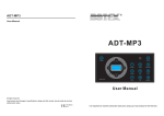
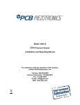
1
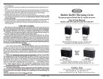
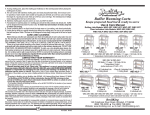
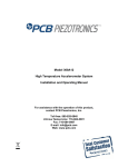
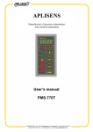
IMI Sensors - A PCB Piezotronics Division
®
Echo Wireless
Vibration System
A simple, affordable, effective wireless vibration system
Why use valuable manpower to collect vibration data on
healthy machines? Why settle for measurements once a
month when you can have them multiple times daily? Why
have people venture into unsafe areas to collect routine
measurements? Echo® Wireless Vibration Sensors can
safely “look” at the machine’s health several times per day
and provide immediate notification when warning or
critical levels are reached. This frees up technical experts,
like certified vibration analysts, for higher value tasks such
as fault analysis.
Toll-Free in USA 800-959-4464
716-684-0003
Transmits very long distances
Batteries last up to 10 years
‘
Eliminates expensive cable runs
Requires no repeaters, networks, or mesh
Run stand alone or with junction box
Stores data in ODBC format
‘
Easily installed
visit us online at www.imi-sensors.com
Echo® Wireless
Vibration System
Introduction
The Echo® Wireless Vibration System has been tested, and found to perform very well, in a number of different types of
plants including: power, steel, food processing, paper, chemical, and automotive. The system has performed reliably and
provided accurate and useful data regarding machinery health.
The Echo® Wireless Vibration Sensor and the EchoPlus® Wireless Junction Box make the set of overall vibration
measurements, listed below, that are sure to provide early warning of most common machine faults. In addition to these
measurements, Echo® provides accurate battery status. Using a user programmable vibration threshold, Echo® can detect
if the machine is not running, and if not, skip a measurement to conserve battery power. It also has an optional Raw
Vibration Output (requires optional Model 070A86 cable) for use with a portable data collector.
RMS Velocity - for “balance-of-plant” faults such as unbalance, misalignment, and flow problems
RMS Acceleration - for higher frequency faults and high frequency energy (HFE) such as high speed
gear mesh, broken rotor bars, and loss of bearing lubrication
True Peak Acceleration - for bearing, gear, and impulsive faults, including looseness
Crest Factor – for fault severity indication
Model 670A01
Wireless Vibration Sensor
The Echo® Wireless Vibration Sensor is a stand alone, battery powered, industrial vibration
sensor. At the default setting of three measurements per day (user programmable) battery life
approaches 10 years. A Raw Vibration (RV) output version includes an integral connector that can
be used with an optional cable and a standard vibration data collector for fault analysis. The
sensor can be programmed via RS-232 (requires optional Model 070A87 cable) to set the
transmission (collection) interval and a Residual Vibration Level (RVL) if desired. Echo® has an LED
that provides visual feedback on the status of the sensor, including: on, off, measuring,
transmitting, or changing states. The sensor has an embedded magnetic switch and can be
activated or deactivated by holding a strong magnet next to the sensor. Upon activation, the
sensor makes and transmits a set of measurements.
2
visit us online at www.imi-sensors.com
Toll-Free in USA 800-959-4464
716-684-0003
Echo Wireless Vibration System
Model 672A01
Wireless Junction Box
The EchoPlus® Wireless Junction Box is an 8-channel junction box that instantly
converts installed industrial sensors to wireless operation. This incredibly economical
device periodically powers each sensor, makes the same set of overall measurements
as Echo®, and transmits them wirelessly. The default transmission interval is 8-hours
but is user programmable. Additionally, it operates as a standard junction box allowing
full data collection with a portable data collector at the box. It can be powered using
either standard 24 VDC or any battery between 6 and 14 VDC. The unit can be used by
itself or in conjunction with an existing junction box by simply jumping wires between
them.
Model 673A01
Receiver
The Echo® Receiver is a stand alone unit that communicates point-to-point with Echo®
Wireless Vibration Sensors and EchoPlus® Wireless Junction Boxes. Operating in the
916 MHz range, using an ultra-narrow bandwidth filter with Extended Range RF (ERRF)
technology, it has unprecedented -145 dBm sensitivity and can detect and decode RF
signals as low as about a millionth of a billionth of a milliwatt. This results in very long
distance point-to-point communications in plants, eliminating the need for repeaters or
complicated mesh networks. Actual tests in a typical power plant achieved successful
signal transmission distances of over 1/3 mile and even through buildings. Outdoor tests
have achieved transmission distances measured in miles, and transmissions are at only
0.75 mW ERP using very little battery power.
The antenna and receiver can be centrally located for optimum RF coverage in plants and the receiver conveniently outputs data to
the nearest Ethernet port. The IP address of the receiver can either be acquired or permanently assigned as required. In the case
where there are too many measurement channels or longer than possible distances for a single receiver, the system is capable of
running multiple receivers on different frequency bands. The sensors and junction boxes can be tuned to operate at any of the 12
bands available.
visit us online at www.imi-sensors.com
Toll-Free in USA 800-959-4464
716-684-0003
LIFETIME
WARRANTY
Products Guaranteed for Life & More!
3
Echo® System Diagram
EchoPlus® Wireless Junction Box
(see page 3 for more infomation)
Optional High
Gain Antenna
100-240 vAC to
12 vDC Universal
Power Supply
Process 24 VDC
power or 6-14 VDC
battery power
TCP/IP
Echo®
Wireless
Sensor
Echo® Receiver
(see page 3 for
more information)
Direct point to point transmission
typical distance = 1/3 to 1/2 mile radius
Traditional,
Wired Sensor
Low Loss
Antenna Cable
(actual distances can vary widely based on conditions)
Echo® Receiver
Echo® Wireless Vibration Sensors
Monitored Machinery
(see page 2 for more information)
Echo® Wireless Vibration Sensor
& EchoPlus® Wireless Junction Box
(shown with optional RV sensor & cable)
Data collector connects directly to
wireless vibration sensor or
wireless junction box
4
visit us online at www.imi-sensors.com
Toll-Free in USA 800-959-4464
716-684-0003
Echo® Receiver
DHCP or static IP
addressing
Echo Wireless Vibration System
PCB Echo® Software (see page 6 for more information)
Echo® Receiver
Data Client
Echo® Data
Presentation SW
Collects Transmissions
Formats Data
Stores in Database
Generates Alarm Email
Server instance is fully
functional SW that also
stores sensor transmissions
in database
Trend Plots
Status
Alarms
Reports
Echo® sensor
configuration utilities
Echo® Data
Presentation SW
Access to SQL Database
through LAN
MS SQL
Server 2005
Ethernet
TCP/IP
Trend Plots
Status
Alarms
Reports
Sensor
Configuration
Echo®
Sensor Data
All monitor stations, either through LAN or remote
access, have all the same functionality as server
system, but do not store data
Echo® Data
Presentation SW
Access to SQL Database
through internet with VPN
Trend Plots
Status
Alarms
visit us online at www.imi-sensors.com
Toll-Free in USA 800-959-4464
716-684-0003
Reports
Sensor
Configuration
LIFETIME
WARRANTY
Products Guaranteed for Life & More!
5
Echo® Data Server
and Database
Echo® sensor data is stored in a Microsoft SQL Server 2005 database. The format is published in the
User’s Manual so it can be accessed by users directly using any ODBC compliant application. The data can
also be exported to a tab delimited spreadsheet file that is suitable for use with Excel or other data
viewing applications for post processing. Additionally, IMI is working on interfaces to legacy condition
monitoring programs and plant monitoring systems. Contact IMI for details.
The Echo® Data Server Software provides two major functions
Collect transmission data reported by the receiver and
stores it in the SQL database
Present Echo® sensor data to the user through an intuitive
and concise interface the includes:
Configuration utilities to setup a machinery database and set alarms levels
Tabular displays to view live and historical data.
Alarm reporting - graphically via system status screens
and electronically via email
Single and multi-sensor plot displays with alarm levels to show trends
Hardcopy report generation for last transmission and alarm events
6
System level sensor status display to warn of low batteries,
low RF signal, or missed measurements
Additional utilities to query and program Echo® Sensors,
EchoPlus® Junction Boxes, and Echo® Receivers.
visit us online at www.imi-sensors.com
Toll-Free in USA 800-959-4464
716-684-0003
Echo Wireless Vibration System
Echo® & EchoPlus® Measurements
Details
Environmental
Specification
RMS Velocity
3 Hz to 2400 Hz
RMS Acceleration
> 2 kHz (2 kHz HP fliter)
True Peak Acceleration
of 2 kHz HP filtered acceleration
Battery voltage at maximum load
For battery status report
Echo® Mechanical Shock
Temperature Range (Electronics)
Temperature Range (Echo® Base)
Humidity
Echo® Enclosure Rating
5000 g through mounting base
-20° to 70° C (-4 to 158° F)
-54° to 121° C (-65° to 250° F)
5% - 95%, non-condensing
IP 67
System Information Provided
Details
Echo® Electrical
Specification
7.2V Lithium Battery (073A20 battery replacement kit)
Yes
-60° to 85° C (-76 to 185° F)
>5 years @ 3-measurements per day, room temperature
>108 ohm
Specification
Date
Derived Peak Velocity
1.414 x RMS Velocity
Echo® Power
Replaceable
Battery Operating Temperature
Battery Life
Electrical Isolation (Case)
RMS Acceleration
High pass filtered for improved HFE detection
Echo® Physical
Derived Peak Acceleration
1.414 x RMS Acceleration
True Peak Acceleration
3.7 sec time sample @ 61.4 kHz sample rate
Modified Crest Factor
True Peak / RMS Acceleration Maximum Value = 16
Battery Status
4-levels, status based on previous transmission @ max load
RF Status
4 - levels
Noise Power
Background noise level (dBm)
Average Power
Average transmission power (dBm)
Average SNR
Difference between Noise and Average Power (dB)
Radio & Standard
Specification
Radio Standard
Proprietary
Modulation
Narrowband FSK
Transmission Range
Certifications
250' to >1 mile radius, installation dependent
Progrmmable from 12 sec to 24 hours in 4 sec increments
(default = 8 hours)
FCC, IC
Dimensions
Base Assembly
Housing
Height (overall)
Weight (including battery pack)
Mounting Thread
Mounting Torque
Sensing Element
Material
Base
Housing Material
Housing Cap
Mechanical Isolator
Mounting
Sealing
Minimum Noise Floor
-155 dBm
Radio Sensitivity
-145 dBm
Frequency Band
Number of RF Bands
Maximum Power (ERP)
0.75 mW
Signal Attenuation
-45 dBm, user selectable for sensors close to receiver
RF Data Rate
20 bps
Time
Sensor / Channel ID
Factory set unique ID
RMS Velocity
1-3/8" Hex
1.6" Dia
4.5"
450 g (15.9 Oz)
1/4-28 Female
2 to 5 ft-lb
Piezo Ceramic Shear
304L Stainless Steel
304L Stainless Steel
Ploycarbonate
Urethane
1/4-28 Stud
O-ring
EchoPlus® Parameter
Specification
Channels per Box
Channels Active
Channel ID
8
User selectable in any combination
Individual factory set unique ID per channel
900 MHz ISM Band
Sensors Supported
ICP® (≤2 sec settling time, 10, 50, 100, 500 mV/g)
12 (User selectable)
Sensor Power Supplied
24 VDC @ 2.2 mA constant current
Channel Gain
Set per channel for sensor normalization (Default set for
100 mV/g accelerometer)
Programming
RS-232 (Echo® sensor requires optional 070A87 adapter.
EchoPlus® uses standard 9-pin serial cable.)
Buffered Sensor Analog Output
Sensor Select timeout
External DC Power
BNC, push SELECT SENSOR
15 min of non-use
24 VDC ±1 V
Number of receivers handled by a single computer
No Limit
External Battery Power (battery not supplied)
6 to 13 VDC
Sensors per receiver @ 3 meas/day, 1% miss rate,
measurement spaced
~400
Over Voltage Protection on Battery Terminals
14 to 30 VDC (Fuse auto resets after voltage removed)
Reverse Polarity Protection
Yes
Transmission Interval
Programmable in 4 sec increments up to 24 hours, default = 8
hours, minimum dependent on the number of active channels
3 Hz, May be limited by sensor FR
15 kHz, May be limited by sensor FR
Transmission Interval
Sensors per receiver @ 3 meas/day, 5% miss rate,
measurements
~2000
Antenna
Integral 1/2" Ceramic
Performance
Specification
RMS Velocity
Analog Integration, FFT Sum
Low Frequency Response
High Frequency Response
Velocity HP Filter
2 Hz, 1-pole RC
EchoPlus® Physical
Velocity LP Filter
2400 Hz, 3-pole Chebyshev
Velocity Resolution
0.001 ips
Velocity Range
4.096 ips
Derived peak velocity
1.414 x RMS Velocity
RMS Accleleration (HP filtered)
Time Sample Average @ 61.4 kHz
Acceration HP Filter
2000 Hz, 4-pole Chebyshev
Acceration LP Filter
Enclosure Rating
Input Connector
Enclosure Material
Size (Height x Width x Depth
Weight
Cord Grips
NEMA 4X, IP 66
Terminal strip
Fiberglas
8 x 6 x 4 in (203 x 152 x 102 mm)
2.88 lb (1.3 kg)
10 Individual, PGME07
15k Hz, 3-pole Chebyshev + 1-pole RC
Echo® Receiver Parameter
Specification
Acceleration Resolution
0.005 g
Power/RS232 Connector
TBD
Acceleration Range
20.48 g
Power
12 DC, 15 W max, Using supplied AC power adapter
Derived Peak Acceleration
1.414 x RMS Acceleration
Minimum True Peak Acceleration Pulse Width
~50 s
Modified Crest Factor
True Peak / RMS Acceleration, Maximum Value = 16
ADC/dynamic range
16 bit / >90 dB
Echo® Frequency Response (±3 dB)
3 Hz to >15 kHz
RS-232
Antennal Connector
Ethernet Connector
LED
Interface
Antenna supplied
Enclosure Rating
TBD
N-female
RJ-45 Waterproof
Power indicator
Ethernet TCP/IP packet containing XML text
916 MHz, Whip SMA w/N connector adapter
TBD
Residual Vibration Level (RVL)
If RVL = 0
Operation Status Indicator
Collect on normal transmission period
Check at normal transmission period and collect data only
if RMS velocity ≥ RVL
LED
Echo® Sensor Activation/Deactivation
Magnetic Switch (MAVT)
If RVL > 0
Echo® Receiver Physical
Enclosure Material
Size Overall (Length x Width x Height)
Weight (without mounting bracket)
Weight (with mounting bracket)
visit us online at www.imi-sensors.com
Toll-Free in USA 800-959-4464
716-684-0003
TBD
8.4 x 7.2 x 2.1 in (213 x 182 x 53 mm)
2.84 lb (1.23 kg)
3.76 lb (1.71 kg)
LIFETIME
WARRANTY
Products Guaranteed for Life & More!
7
Predictive Maintenance
Echo® Wireless Accessories
Model 070A86
Echo® RV Output Cable
When used in conjunction with a portable data collector, it
converts standard sensor power to the low voltage required by
Echo® and allows normal broadband data collection with the RV
Echo® Sensor.
Model 070A87
Echo® Programming Cable
This special RS-232 to Micro USB cable allows serial
communication with the mating Micro USB connector in the
Echo® Sensor.
Model 070A88
Echo® RV Shorting Cap
This is used on the RV670A01 Echo® Sensor for normal wireless
use. When removed, the Model 070A86, Echo® RV Output Cable
can be used for data collection with a portable data collector.
Model 073A20
Echo® Replacement Battery Kit
The kit includes a battery pack, o-ring, silicon grease, foam
compressor, and instructions.
Model 009M201
Echo® Receiver Serial Cable
Special serial cable that mates with the industrial MIL
style connector on the Echo® Receiver
Antennas, Low Loss Antenna Cable, and Antenna Accessories are available through many commercial outlets
such as L-com (www.L-com.com). IMI Sensors can, however, quote these if desired. Contact IMI for details.
3425 Walden Avenue, Depew, NY 14043-2495 USA
Toll-Free in USA 800-959-4464
24-hour SensorLineSM 716-684-0003
Fax 716-684-3823 E-mail [email protected]
Web Site www.imi-sensors.com
ISO 9001 CERTIFIED A2LA ACCREDITED to ISO 17025
© 2011 PCB Group, Inc. In the interest of constant product improvement, specifications are subject to change without
notice. PCB, ICP, Modally Tuned, Spindler, Swiveler and TORKDISC are registered trademarks of PCB Group. SoundTrack
LXT, Spark and Blaze are registered trademarks of PCB Piezotronics. SensorLine is a service mark of PCB Group. All other
trademarks are property of their respective owners.
Printed in U.S.A.
IMI Sensors designs and manufactures a full line of accelerometers,
sensors, vibration switches, vibration transmitters, cables and
accessories for predictive maintenance, continuous vibration
monitoring, and machinery equipment protection. Products include
rugged industrial ICP® accelerometers, 4-20 mA industrial vibration
sensors and transmitters for 24/7 monitoring, electronic and
mechanical vibration switches, the patented Bearing Fault Detector,
high temperature accelerometers to +900 °F (+482 °C), 2-wire Smart
Vibration Switch, and the patented Reciprocating Machinery
Protector. CE approved and intrinsically safe versions are available
for most products.
Visit www.imi-sensors.com to locate
your nearest sales office