1
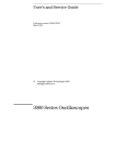
LadyBug Technologies LLC
Automated PowerSensor+ Field Certification Procedure
Procedure Applies to Following Power Sensors
LB478A, LB479A, LB480A, LB559A, LB579A, LB589A, LB679A, LB680A
PowerSensor+ Field Certification Procedure
11/14/2012
Contents
Purpose: ............................................................................................................................................3
Products Covered by Procedure:.........................................................................................................3
Overview: ..........................................................................................................................................3
Required Equipment: .........................................................................................................................4
Test Procedure:..................................................................................................................................7
1.
Setup the test system..............................................................................................................7
2.
Warm-up of equipment...........................................................................................................8
3.
Start the Excel-based Field Certification Software ....................................................................8
4.
Enter Cal Lab Information .......................................................................................................9
5.
Configure the “Source”, “CAL_SENSOR” and “REF_SENSOR” in the software.............................9
6.
Start the Automated Certification Process ............................................................................. 14
7.
Physical Inspection of the UUT .............................................................................................. 18
8.
Measuring Absolute Level Accuracy and Linearity .................................................................. 19
9.
Save and View Data and Certificate ....................................................................................... 22
2
PowerSensor+ Field Certification Procedure
11/14/2012
Purpose:
This documents the field certification process for LadyBug Technologies LLC (LadyBug) PowerSensor+
line of products using an automated procedure (Ladybug’s Automated Field Certification software) and
is intended to satisfy the needs of traceable annual recalibration. In addition, this procedure is useful for
recertifying sensors whose connectors have been replaced with connectors of an identical type (e.g. NType male with N-Type male or N-Type male with N-Type female) (where the internal calibration factors
do not need to change).
Any sensors failing this certification procedure, or if a sensor’s connector is type is changed (e.g.
changed from Type-N to SMA) the sensor must be returned to the factory for repair and/or recalibration (new calibration factors generated).
Products Covered by Procedure:
This procedure applies to the following LadyBug PowerSensor+ products listed below:
LB478A, LB479A, LB480A, LB559A, LB579A, LB589A, LB679A, LB680A
Overview:
This procedure applies to sensors that are in good working order, fully functional and without
mechanical defect or damage. If there is any question about the serviceability or functionality of the
sensor, consult the “User’s Manual” to ascertain the state of the sensor or contact LadyBug
Technologies LLC for advice. This procedure consists of six steps:
1.
2.
3.
4.
5.
6.
7.
8.
Setup of the test system
Warm Up
Enter Cal Lab information
Configure SOURCE and select REF_SENSOR and CAL_SENSOR
Physical inspection of UUT
Absolute level accuracy Test
Linearity Test
Save and print data package and certification
As with any procedure, it is impractical to verify all conditions and states. So, the procedures test a
selected set of measurement points. These points are sufficient to ensure a high level of confidence in
the sensor’s continued performance. As with all calibration procedures, there is great reliance on the
experience, knowledge, sound judgment and skill of those doing the work.
Certification traceability to national standards is accomplished through a locally calibrated SOURCE and
factory calibrated CAL_SENSOR and REF_SENSOR.
3
PowerSensor+ Field Certification Procedure
11/14/2012
Required Equipment:
This section lists the equipment required for the certification procedure. This procedure refers to
equipment by “Name” rather than model number. For example, rather than refer to an “HP 8340B” (see
Table 1) the calibration procedure refers to “SOURCE”. This term, “SOURCE”, comes from the Required
Equipment table Procedure Name column. In addition, the uncertainties used within the procedure to
certify the UUT are based on using “REF_SENSOR” and “CAL_SENSOR” power meters from LadyBug
Technologies.
Necessary equipment and software (refer to Table 1 for recommended models):
1) Ladybug Field Certification SW Rev 1.0 (MS Excel based software) downloadable from www.ladybugtech.com
2) A computer running Windows XP or Windows 7: required to operate the LB Power Meter Application
for each sensor connected (REF_SENSOR, CAL_SENSOR, UUT_SENSOR) and MS Excel.
3) Microsoft Excel 2007 or newer: the automated program is embedded with Excel as a macro, using
Excel to provide a useful user interface and data management structure.
4) SOURCE: a stable, repeatable, and GPIB programmable signal generator with sufficient frequency and
power range (and resolution) to test the UUT (Unit Under Test) or multiple UUT’s;
5) SPLITTER: a 2-resistor uW power splitter that is specified over the necessary frequency range of the
UUT’s to be tested. It is recommended that a quality, broadband power splitter that operates from 10
MHz to 26.5 GHz be used;
6) CAL_SENSOR: a factory calibrated Ladybug USB power sensor that has the same connector type and
sex that is present on the UUT and provides frequency coverage that meets or exceeds that of the UUT.
If there are multiple UUT’s with different RF connector types and sex, multiple CAL_SENSOR’s will be
needed;
7) REF_SENSOR: a factory calibrated Ladybug USB sensor that provides frequency coverage that meets
or exceeds that of the UUT being tested to ensure that the same power level (at each frequency) is
delivered to both the CAL_SENSOR and UUT ;
8) CAL_ADAPT: an RF adapter that presents the same RF connector interface between both the
UUT_SENSOR and the CAL_SENSOR and the broadband SPLITTER. This approach minimizes mismatch
error within the test. If the UUT_SENSOR and CAL_SENSOR RF connector directly connect to the
SPLITTER without the use of any adapter, then a CAL_ADAPT is not required.
9) A USB 2.0 powered hub may be needed to ensure that all of the sensors can be powered and
operated at the same time: ensure that the hub can deliver 500 mA of current at each of its ports at the
same time.
10) High quality cables and precision adapters to connect the SPLITTER to the SOURCE and to the
REF_SENSOR and UUT_SENSOR/CAL_SENSOR. This hardware is not called out in the equipment list.
4
PowerSensor+ Field Certification Procedure
11/14/2012
11) VISA IO libraries installed on the PC: the software uses SCPI or other GPIB commands to
communicate with the SOURCE.
12) A USB 2.0 to GPIB adapter such as Agilent 82357B, or equivalent GPIB capability.
This procedure applies to several sensors and connectors. Understandably, the equipment
requirements vary. However, some of the equipment applies to all sensors. Other equipment varies by
the UUT model number and UUT connector type and UUT connector sex. Pay special attention to the
type of UUT you are certifying when selecting your equipment.
If you choose to substitute equipment consult the equipment list for information. Also, be aware of the
test range for each sensor. These test ranges for each sensor are shown below:
LB478A: 10 MHz – 8 GHz
LB479A: 10 MHz – 8 GHz
LB480A: 50 MHz – 8 GHz (100 MHz – 8 GHz for LB480A serial numbers <117xxx)
LB559A: 10 MHz – 12.5 GHz
LB579A: 10 MHz – 18 GHz
LB589A: 10 MHz – 26.5 GHz
LB679A: 50 MHz – 18 GHz
LB680A: 50 MHz – 18 GHz
When selecting your equipment be sure to check the equipment for damage or excessive wear. SWR or
match is the single biggest contributor to error and uncertainty in power measurements. So, using worn
or damaged connectors during calibration can induce “false failures”.
This same advice applies when selecting cables. Use high quality cables during calibration. And ensure
they are in good working order. Also, when building the setups, keep cables as short as possible and
keep the strain on the cables at a minimum.
Finally, if you choose to substitute any of the passive devices (adapters, attenuators or splitters) pay
close attention to specified SWR or match. It is recommended that the SPLITTER and CAL_ADAPT
components be of high quality.
Keep in mind that SWR or match is the single biggest contributor to error and uncertainty. As such,
selecting components with marginal performance will degrade the quality of the measurements and can
easily induce “false failures” during calibration.
Note: When testing LB480A units, the 50 MHz calibration point will be measured and displayed only for
units that have a serial number of 117xxx or larger. All other units will be re-calibrated starting at 100
MHz carrier frequency.
5
PowerSensor+ Field Certification Procedure
Procedure Name
UUT Connector
Sex
11/14/2012
Equipment Model Number
Comments
Type
UUT
ALL
ALL
Unit Under Test
The sensor you wish to calibrate
TR
ALL
ALL
Test Record
The test record is selected in step 1
PC
ALL
ALL
PC running Windows XP, Service Pack 3 or Windows 7and up
to date. Include Excel 2007 or newer, Agilent IO Libraries 16.
Keyboard, mouse etc as required, Agilent
82357B USB-GPIB interface or equivalent
PM_APP
ALL
ALL
Power meter application. Software available for download
from: http://www.ladybug-tech.com/
Power Meter application is part of
standard application installation.
SOURCE/Signal
Generator
ALL
ALL
Agilent N5183A or equivalent with adapaters and cable
necessary to connect to the SPLITTER 3.5 mm female RF
input.
Suitable substitutes with equal to or better:
Harmonics, Power range (-100 dBm - +20 dBm)
SPLITTER
F
SMA/3.5
mm
USB Hub
Frequency range and is programmable
Agilent 11667B , 2 resistor splitter, 26.5 GHz or equivalent
Powered USB 2.0 Hub with 500 mA at each USB port
REF_SENSOR
M
SMA
LB589A Opt OSM
Recommended Factory calibrated sensors
CAL_SENSOR
M
N-Type
LB579A Opt ONM
Recommended Factory calibrated sensors
F
N-Type
LB579A Opt ONF
M
SMA
LB589A Opt OSM
F
SMA
LB589A Opt OSF
M
N-Type
F
N-Type
N female to SMA male or N female to 3.5 mm male
N male to SMA male or N male to 3.5 mm male
M
SMA
No adapter necessary, but if you choose one it must be
either a SMA female to SMA male or 3.5 mm female to 3.5
mm male
F
SMA
SMA male to SMA male or 3.5 mm male to 3.5 mm male
CAL_ADAPT
Table 1: Required Equipment
6
If configuring your own splitter with SMA
female or 3.5 mm female connectors, and
your own CAL_ADAPT, select the cal
sensor adapter based on the UUT
connector type and UUT connector sex
always to 3.5 mm male (for example: Nfemale to 3.5 mm male for UUT connector
type of Type N male)
PowerSensor+ Field Certification Procedure
11/14/2012
Test Procedure:
1. Setup the test system
Configuration Diagram for Field Calibration procedure
Use high quality cables and adapters when making all RF connections. It is recommended that an
appropriate torque wrench be used on all RF connections to ensure stable and repeatable RF
connections are made.
When configuring the test system above, only one programmatic connection to the SOURCE is
necessary: GPIB or USB, which ever interface the signal generator supports (newer signal generators
may support both). In addition, install the VISA IO libraries on the PC you will be using.
a) Copy the LadyBug Power Sensor Field Certification folder to the PC’s desktop or to a
permanent location on the PC’s C: drive with a shortcut installed on the desktop .
7
PowerSensor+ Field Certification Procedure
11/14/2012
b) This sw requires Excel 2007 or 2010, and the LB PM sw to be installed on the PC. It also
requires Agilent IO libraries to be installed on the PC. In addition, the PC must be capable of
connecting 3 ea LB USB power sensors and 1 USB-GPIB interface (Agilent82357B) – otherwise
a powered USB hub must be used.
c) Connect the “REF_SENSOR”, “CAL_SENSOR”, and UUT sensors to the PC (using a power hub if
necessary)
d) Connect the “SOURCE” and connect the “SPLITTER” (and cables). Connect the
“REF_SENSOR” and the “CAL_SENSOR” and “CAL_ADAPT” (if necessary) to the “SPLITTER”.
2. Warm-up of equipment
a) For 24 hours prior to and during execution of this test procedure the UUT must be in a stable
laboratory environment. In addition, all sensors should be powered for at least 1 hour before starting
the test. Stable environmental conditions are defined as:
Temperature: 20 C to 30 C (68°F to 86°F)
Humidity: 15% to 95% non-condensing
Altitude: Sea Level to 3,000 meters (10,000 feet)
b) All equipment requiring power should be connected to mains and warmed up per manufacturers
recommendations.
3. Start the Excel-based Field Certification Software
a) Open the LadyBug Power Sensor Field Certification folder and start the Excel based Field
Certification sw. At this point you should see the following screen:
8
PowerSensor+ Field Certification Procedure
11/14/2012
b) The next step will be to enter the appropriate information for the company (Cal Lab)
performing the Field Certification.
4. Enter Cal Lab Information
a) Select “Edit Calibration Lab Information” on the main sw panel. This selection brings up the
following screen:
Clear the form and enter the appropriate information for the company providing the
certification services. This information will be included on the certification data package and
the certification of cal report that is generated when the UUT testing is complete. Select
“Finished” when done, this will close this window and return the the main screen. If this
information is not provided before starting the Certification process, the sw will require the
user to complete the information before continuing.
5. Configure the “Source”, “CAL_SENSOR” and “REF_SENSOR” in the software
a) Select “Press to Configure System” on the main screen. A new screen will be presented
where you can select the “Configure Source” tab. If the source
you plan to use supports multiple programming languages in
addition to SCPII, ensure that the SCPII mode has been selected
and that the source is set to the GPIB address configured in the
software (normal source GPIB address is “19”).
9
PowerSensor+ Field Certification Procedure
11/14/2012
The “Define Source” screen allows you to: a) use the
current source selected (highlighted source), b) to
select a source from the list provided, or c) to select the
<New Source> selection and enter the proper
information for the source being used.
To use the currently configured source, verify that all of
the information shown on the panel is correct, especially
the “Address” and select “Continue”.
To select a source from the list provided, highlight the
source model number and then select continue.
Within the “Source Details” panel, verify that the
information provided for the selected source is correct
and then select “Continue”
10
PowerSensor+ Field Certification Procedure
11/14/2012
To use a source that is not listed, select <New
Source> . The following screen is presented
immediately for you to enter the model number of
the new source, then select “OK”:
A new Define Source screen will be presented with
the new source model number at the top. Enter the
Address, Serial Number, Manufacturer and the
Calibration Due Date on this form before selecting
“Continue”
For the Source Details screen below, Enter the
manufacturer of the source in the top line. If the
source is SCPII compliant, select “Copy SCPII
Commands” and then “Continue”. If the source is
not SCPII compliant, manually enter the
programming commands for each function and then
select “Continue”.
11
PowerSensor+ Field Certification Procedure
11/14/2012
Once the Source has been configured, select “Exit”
b) Select “Configure Calibration Sensor”:
The following screen will appear. Select the model and
serial number of the Ladybug sensor that will be used as
the “CAL_SENSOR” and select “Continue”:
12
PowerSensor+ Field Certification Procedure
11/14/2012
c) The following screen will appear when you select
“Continue”:
Select “Configure Reference Sensor” . The following screen
will appear. Select the model number and serial number of
the sensor that will be used as the “REF_SENSOR” and
select continue.
Now select “Exit” to return to the main screen of the
sw.
13
PowerSensor+ Field Certification Procedure
11/14/2012
6. Start the Automated Certification Process
At this point, the hardware is connected, has been allowed to warm-up, and
has been configured within the software.
a) Select “Press To Start Certification Process”.
At the start of the certification process, the
source is checked to see if it is the one that
has been configured. If a SCPII source
different than the one that is configured
has been connected, but the GPIB address
is the same, this message may appear. If
the detected source is the one you are
using, select “Yes” and continue.
14
PowerSensor+ Field Certification Procedure
11/14/2012
Select the UUT model
and serial number to be
tested.
Once the UUT is
selected, select “Test
Device”.
b) If this is the first
certification of the
day, select
“calibrate”.
15
PowerSensor+ Field Certification Procedure
11/14/2012
Calibrating the test setup will require the “Cal_Sensor” to be connected at the
measurement port. The process will measure the “Cal_Sensor” and use its
measured data to certify the performance of the UUT sensor. Ensure that you
are using the same “Cal_Adapter” that the UUT will use.
Connect the “Cal_Sensor” to the measurement port and select “Calibrate”.
This step ensures that you have connected the
“Cal_Sensor” before continuing. Select “OK” to
measure the “Cal_Sensor”.
Once the calibration measurement has been
completed, select “OK” to continue.
16
PowerSensor+ Field Certification Procedure
11/14/2012
Select “Calibration Complete” to continue
c) Select “Test” to continue the process.
17
PowerSensor+ Field Certification Procedure
11/14/2012
7. Physical Inspection of the UUT
Before connecting the UUT sensor to the measurement port, it is necessary to
perform a physical inspection of the UUT and its RF connector. It is very
important that the RF connector is clean and without physical damage.
Inspect the UUT’s RF connector for physical damage. If the RF connector is
damaged to the extent that it cannot be connected to the CAL_ADAPT, replace
the connector with a new, identical type and sex before continuing with the
re-calibration. If the RF connector shows wear or is damaged but can be
connected to the CAL_ADAPT, proceed with the re-calibration after warm-up.
If the unit passes re-calibration with the wear or slight damage, it can be
certified as calibrated. If the wear or slightly damaged unit fails the re-cal
tests, replace the RF input connector (see above) and re-test. If the unit fails
the re-cal test after the RF connector has been replaced, the unit must be sent
back to the factory for repair.
Once you have inspected the UUT and it has no physical damage and RF
connector shows no sign of wear or damage, check the boxes on the left and
select “Inspection Complete”.
18
PowerSensor+ Field Certification Procedure
11/14/2012
8. Measuring Absolute Level Accuracy and Linearity
At this step, remove the “Cal_Sensor” from the measurement port and connect
the UUT sensor. Once the UUT has been connected using the same “Cal_Adapt”
that was used when measuring the “Cal_Sensor”, select “Measure”
19
PowerSensor+ Field Certification Procedure
11/14/2012
The measurement process will begin and the sw will start to complete the
certification data page.
This data report will be completed as the UUT is measured.
Once the report is complete, you will need to record ambient temperature and
humidity for the report.
20
PowerSensor+ Field Certification Procedure
11/14/2012
At this step, if the unit has no “failures”, select “Test complete”
If there have been any failures, select “cancel” and start the process over,
starting with calibrating the system.
21
PowerSensor+ Field Certification Procedure
11/14/2012
9. Save and View Data and Certificate
If the UUT has passed, select “Save and View Data”
The Certificate of Calibration and the Cal Data Report will be saved as a .pdf
using the model and sn in the title of the file and shown for your review.
These .pdf files will be saved in the “Reports” folder located within the
“LadyBug Power Sensor Field Certification” folder on the desktop. These files
can be retrieved and printed when convenient.
22
PowerSensor+ Field Certification Procedure
11/14/2012
This completes the certification process for the selected UUT.
If you have other UUT’s of the same RF connector type that are connected via
USB and have been warmed up, you can start the process again, this time
skipping the calibration process, or select “Exit” to return to the main screen.
Certification failures can be caused by:
1) a defective UUT;
2) a defective CAL_Sensor
3) a defective calibration measurement, usually caused by faulty RF
connections when connecting the Cal_Sensor or the UUT sensor.
23