1
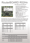
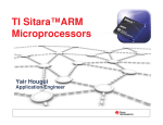
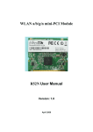
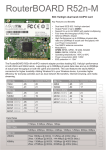
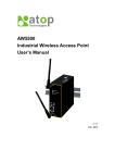
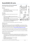
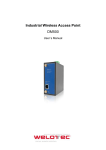
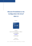
VIP Program: eStadium
Wireless Subteam
Recommendation of North End Zone Concession Area
Wireless Network
For Bobby Dodd Stadium
Last Revised: October 20, 2011
Adam Bommer
Christopher Holmes
Brian Kwak
Gautam Meka
Introduction
The following proposal discusses two solutions for designing a wireless mesh network for Bobby Dodd
Stadium. A mesh network is necessary in the Bobby Dodd stadium to provide Wi-Fi access to clients and
to relay data from the cluster head of the sensor network. The first option recycles more hardware
already in the possession of the eStadium team and is more cost-efficient to implement. However, it is a
temporary solution and serves better as a test bed. The second option requires more new hardware in
the form of new router boards or custom PC’s, wireless cards, and wireless embedded devices supplied
by Texas Instruments. The second option offers a longer life cycle and is more flexible for future
modifications.
Mesh networks consist of a gateway and mesh nodes that operate on an IEEE 802.11a network. The first
mesh node receives the signal from the gateway and then relays the signal to the next node. The
throughput of a mesh network degrades by approximately half with each hop through the network.
Therefore, no more than three hops are implemented for the mesh network designs.
Network Topology
The North end zone concession stand area wireless network will include the backbone for the sensor
network, the backbone for the wireless network, and provide wireless coverage for end users. Network
accessibility will come from the data closet in the south east corner of the concession area. A gateway
will be needed to get network accessibility from the data closet to the new networks. Nodes of the
wireless mesh network will be placed on the columns in the concession area to extend coverage for the
wireless data network and to extend the sensor network backbone.
The gateway will need an Ethernet interface to connect to the switch located in the data closet. This
Ethernet connection will provide network access to the entire deployment. Two wireless interfaces are
essential for the gateway while a third could be used to increase the coverage area of the wireless data
network. A single wireless interface on the gateway will be used to forward data on the backbone of the
wireless data network over 802.11a (5 GHz). The second wireless interface is needed to forward sensor
data over 802.11b/g using channel 6 for the backbone of the sensor network. The optional third wireless
interface could be used to broadcast data over 802.11b/g on channel 1 or 11 to end users of the
eStadium network.
A node of the wireless mesh network will need to consist of 3 wireless interfaces. The first wireless
interface will be used for the Mesh Local Area Network (MLAN). This will be the backbone of the
wireless data network which will use 802.11a (5 GHz) to transmit data. The second wireless interface will
be used for the Sensor Backbone Local Area Network (SBLAN). This will be the backbone of the sensor
network which will use 802.11b/g on channel 6 to forward data. The SBLAN will have a dedicated
wireless network to ensure better reliability and throughput for the data received from the sensors. The
third wireless interface in each node will be used to forward data from the MLAN to end users of
eStadium. This will be done over 802.11b/g using channels 1 or 11.
Hardware Options
Router boards are designed with different configurations and options including number of mini-PCI
slots, number of Ethernet ports, and USB ports. All the models come with sufficient processing power
and memory necessary for the eStadium network. The number of mini-PCI slots limits the number of
wireless cards that can be added to the router board. USB ports will make installing Linux much easier.
Without USB ports, Linux will be installed over Ethernet. Ethernet ports are required for connecting to
wired networks.
Table 1. Router board specifications.
Model
RB411
RB433
RB433AH
RB433UAH
RB435G
ALIX2D2
ALIX3D3
ALIX3D2
net4526-30
CPU
300MHz
300MHz
680MHz
680MHz
680MHz
500MHz
500MHz
500MHz
133MHz
Memory
32MB
64MB
128MB
128MB
256MB
256MB
256MB
256MB
64MB
mini-PCI
1
3
3
3
5
2
2
2
2
Ethernet
1
3
3
3
3
2
1
1
1
PoE
Yes
Yes
Yes
Yes
Yes
Yes
Yes
Yes
Yes
USB
0
0
0
2
2
2
2
2
0
Memory Expansion
None
MicroSD
MicroSD
MicroSD
MicroSD
Compact Flash
Compact Flash
Compact Flash
Compact Flash
Price
$49.00
$99.00
$149.00
$165.00
$189.00
$129.00
$132.00
$129.00
$135.00
Figure 1 shows the different models of router boards that we looked at and their specifications that we
found important. With one mini-PCI slot, a router board can use one wireless card which can connect to
two patch antennas as seen in Figure 1.
Router Board
Patch
Antenna
Wireless Card
Patch
Antenna
Figure 1. Router board with one mini-PCI slot.
The more expensive router boards have multiple mini-PCI slots for multiple wireless cards. Two
antennas can be attached to each wireless card. Figure 2 shows a router board with three wireless cards
and six antennas.
Router Board
Patch
Antenna
Wireless Card
Patch
Antenna
Patch
Antenna
Patch
Antenna
Wireless Card
Wireless Card
Patch
Antenna
Patch
Antenna
Figure 2. Router board with 3 mini-PCI slots.
A custom built PC could be used in place of the router board. The PC can be designed with low grade
solutions for the CPU, RAM, memory, and power supply. The main variable for the motherboard is the
number of PCI slots which matches to the number of wireless cards. Figure 3 shows a layout of a custom
PC solution.
Patch
Antenna
Patch
Antenna
PSU
CPU
Wireless Card
PCI Adapter
Wireless Card
RAM
HDD
PCI Adapter
Wireless Card
Motherboard
PCI Adapter
Patch
Antenna
Patch
Antenna
Patch
Antenna
Patch
Antenna
Figure 3. Custom PC design as a mesh node.
Table 2 shows the prices and specifications for a custom PC. The motherboard has 3 PCI slots to allow
for multiple wireless cards. The custom PC solution costs approximately the same price as one of the
router boards. Therefore, the router board was chosen for both solutions since it is an integrated
solution and has a smaller form factor.
Table 2. Custom PC specifications and prices.
Specifications
Price
Motherboard
3PCI Slots
$50.00
CPU
2.8GHz
$40.00
Memory
1GB
$9.00
PSU
350W
$30.00
HDD
40GB
$20.00
Total
$149.00
The wireless cards that are needed for the router board are designed with three main differences:
output power, WiFi standard, and Connector type. Table 3 shows the prices and specifications for
various wireless cards.
Table 3. Wireless cards specifications and prices
Model
R52
R52H
R52Hn
R52nM
WiFi Mode
abg
abg
abgn
abgn
Output Power
19dBm
25dBm
25dBm
23dBm
Connector
uFl
uFl
MMCX
MMCX
No. of Connectors
2
2
2
2
Price
$49.00
$59.00
$59.00
$59.00
A WiFi embedded system that could be connected to the cluster head as part of the SBLAN is a Texas
Instruments WL1271 board. This is an embedded device that has a 1 GHz ARM processor, 256 MB of
RAM, a 3.7” touch screen, and an 802.11b/g/n integrated wireless card with a uFl connector for an
external antenna.
Adapters will be needed in order to connect the Cisco patch antennas to the wireless cards. Depending
on the wireless card, two different adapters could be used.
Table 4. Adapter Specifications and Prices
Model
ACUFL
ACMMCX
Type
uFl to Nfemale
MMCX to Nfemale
Price
$15.00
$15.00
The Linksys WRT160NL access point could be used along side the custom PC or router boards. The
WRT160NL operates on the 802.11b/g/n standard at the 2.4GHz frequency range. Two Cisco patch
antennas can be attached to the AP.
Network Design
The first option for the network design uses a combination of router boards and access points. The
gateway will consist of one router board with a single mini-PCI slot and a Linksys WRT160NL access
point. The only router board in table 3 with one mini-PCI slot is the RB411. It also has an Ethernet port
which will be connected to a switch in the data closet to give network access. The wireless card on the
RB411 needs to have 802.11a capabilities and have a high output power. The R52Hn was chosen for
these reasons. The wireless card on the router board will be broadcasting the wireless backbone. To
broadcast the sensor network backbone, the access point will be used. It will operate on the 802.11b/g
standard using channel 6. The WAN port on the access point will also be connected to the switch to give
it network access. The gateway is priced at 120 dollars not including the access point and patch
antennas since nine access points and eight antennas have been purchased. Eventually addition APs and
antennas will need to be purchased for future deployments in other parts of the stadium.
The mesh nodes will be a combination of a router board and two access points. The WRT160NL and
RB411 will also be used for the mesh nodes. The router board will operate on the 802.11a standard and
will be forwarding data back to the gateway. The Ethernet port on the router board will be connected to
an access points switch in order to give the access point network access. The access point will then
broadcast the wireless network for the end users to connect to. The second access point will be used as
a node in the sensor network backbone. It will operate on the 802.11b/g standard using channel 6 so
that it can pass data to the sensor network backbone access point connected to the switch in the data
closet. The multiple mesh nodes in the network design will be identically configured. The mesh node is
priced at 120 dollars excluding the access points and patch antennas. Once again, additional APs and
antennas will need to be purchased for future deployments.
SB
AP
RB
SB
AP
AP
RB
M
MLAN 802.11a
M
SLAN 802.11s
CH
SBLAN 802.11b/g
WL1271
SB
GW
M
Switch
Data Closet
Figure 4. Network design option one for the north end zone concession area.
RB
Figure 4 shows the network design for the SLAN, SBLAN, MLAN, and WLAN. The SLAN operates on the
802.11s standard at the 2.4 GHz frequency range. The SBLAN operates on the 802.11b/g standard on
channel 6 at the 2.4 GHz frequency range. The MLAN operates on the 802.11a standard at the 5 GHz
frequency range. The WLAN operates on the 802.11b/g standard on channels 1 or 11 at the 2.4 GHz
frequency range. In the SLAN section of the figure, the clusterhead is designated by CH and the motes
are designated by M. In the SBLAN section, the sensor network backbone access point is denoted by SB.
In the WLAN section, the wireless data network access point is denoted by AP. In the MLAN section, the
wireless data backbone is denoted by RB.
The second option for the network design uses only router boards with multiple wireless interfaces to
operate on the SBLAN, MLAN, and WLAN. The RB433AH router board with 3 mini-PCI slots was chosen
for the design. The R52Hn was chosen again for its 802.11a/b/g/n capabilities and high output power.
This option will require three of the R52Hn wireless cards per RB433AH. The hardware of the gateway
and mesh nodes are identical while the software is configured differently for the different functions. The
first wireless interface will be set to 802.11a and will operate as the wireless network backbone. The
second wireless interface will act as the sensor network backbone and will operate on the 802.11b/g
standard using channel 6. A third wireless interface will broadcast the wireless data network for the end
users. The gateway/mesh nodes are priced at 330 dollars not including any addition antennas needed
for deployment. Extra patch antennas will need to be purchased since this design utilizes 9-12 antennas
depending on the desired coverage area. One antenna will be used for the SBLAN, one antenna will be
used for the MLAN, and one or two antennas will be used for the WLAN.
MN
MN
WLAN 802.11b/g
M
SBLAN 802.11b/g
M
SLAN 802.11s
CH
MLAN 802.11a
WL1271
GW
M
Switch
Data Closet
Figure 5. Network design option two for north end zone concession stand area.
Figure 5 shows the network design for the SLAN, SBLAN, MLAN, and WLAN. The SLAN operates on the
802.11s standard at the 2.4 GHz frequency range. The SBLAN operates on the 802.11b/g standard on
channel 6 at the 2.4 GHz frequency range. The MLAN operates on the 802.11a standard at the 5 GHz
frequency range. The WLAN operates on the 802.11b/g standard on channels 1 or 11 at the 2.4 GHz
frequency range. In the SLAN section of the figure, the clusterhead is designated by CH and the motes
are designated by M. In the other networks, the mesh nodes are designated by MN and the gateway is
designated by GW.
Recommendation
Option two provides a better solution for the wireless network and sensor network backbone in the
north end zone concession area. The biggest problem with technology is how quickly it becomes
obsolete. Option two leaves room for expansion and improvement to the network as option one does
not. When the PoE cable is eventually run to the nodes, the wireless cards that were originally being
used for the backbone can be switched in software to broadcast the wireless data network. With extra
wireless interfaces broadcasting the wireless data network, newer standards such as 802.11n can be
utilized which will improve throughput. This will provide more thorough coverage as well as increasing
the amount of users that the network will be able to handle. Since the router boards are equipped with
PoE, only a single cat5 cable will be needed at each node. To eliminate the mesh network in option one,
multiple cat5 cables will need to be run to each node increasing cost in the future.
Option two provides a solution that is physically smaller and more compact. This will help keep the
impact of the deployment to a minimum while still providing quality of service. Option two is physically
smaller due to the fact that is it a much more integrated solution. In option one, there are many
different units that are hooked together to create the mesh network. Whenever multiple pieces are
being connected, it provides more places for things to malfunction and therefore can be a more
unreliable network. In conclusion, we recommend that option two be deployed as it uses specialized
hardware which leaves room for expansion in the future and keeps the overall footprint of the
deployment to a minimum.
An important consideration is the price to deploy in the north end zone concession area and also the
price for future deployments where all the equipment needs to be purchased. Option one can be
deployed in the North end zone concession area for a total cost of $405 and future deployments can be
purchased for $410 per node. Option 2 can be deployed in the North end zone concession area for a
total cost of $1125 and future deployments can be purchased for $825.
Appendix A: Data Sheets
RouterBOARD R52Hn
802.11a/b/g/n dual band miniPCI card
•
•
•
•
•
•
•
•
•
•
•
•
•
•
Dual band IEEE 802.11a/b/g/n standard
Output Power of up to 25dBm @ a/g/n Band
Support for up to 2x2 MIMO with spatial multiplexing
Four times the throughput of 802.11a/g
Atheros AR9220, chipset
High Performance (up to 300Mbps physical data
rates and 200Mbps of actual user throughput) with
Low Power Consumption
2 X MMCX Antenna Connector (J4 - Chain 0)
Modulations:
OFDM: BPSK, QPSK, 16 QAM, 64QAM
DSSS: DBPSK, DQPSK, CCK
Operating temperatures: -50ºC to +60ºC
Idle power consumption 0.4W
Max power consumption 7W
MiniPCI IIIA+ design (3mm longer than MiniPCI IIIA)
1.5mm heatsink, 3mm RF shield thickness
±10KV ESD protection on RF ports
RouterBOARD R52Hn miniPCI network adapter provides leading 802.11a/b/g/n performance in both
2GHz and 5GHz bands, supporting up to 300Mbps physical data rates and up to 200Mbps of actual
user throughput on both the uplink and downlink. 802.11n in your Wireless device provides higher
efficiency for everyday activities such as local network file transfers, Internet browsing, and media
streaming. R52Hn has a high power transmitter, bringing you even more range.
RX Sensitivity
TX Power
-93
-93
24
24
-94
-81
25
22
-94
-92
-78
-75
25
24
21
20
802.11a
6Mbit
54Mbit
802.11n 5GHz
MCS0 20MHz
MCS0 40MHz
MCS7 20MHz
MCS7 40MHz
RX Sensitivity
TX Power
-97
-80
25
21
-97
-92
-77
-74
24
22
18
17
Data Rates
802.11b
11Mbps; 5.5Mbps; 2Mbps; 1Mbps
802.11a/g
54Mbps; 48Mbps; 36Mbps; 24Mbps; 18Mbps; 12Mbps; 9Mbps; 6Mbps
802.11n
20MHz
40MHz
1Nss: 65Mbps @ 800GI, 72.2Mbps @ 400GI (Max.)
2Nss: 130Mbps @ 800GI, 144.4Mbps @ 400GI (Max.)
1Nss: 135Mbps @ 800GI, 150Mbps @ 400GI (Max.)
2Nss: 270Mbps @ 800GI, 300Mbps @ 400GI (Max.)
routerboard.com
802.11b
1Mbit
11Mbit
802.11g
6Mbit
54Mbit
802.11n 2.4GHz
MCS0 20MHz
MCS0 40MHz
MCS7 20MHz
MCS7 40MHz
RouterBOARD 411
Quick Setup Guide and Warranty Information
Assembling the Hardware
First use of the board:
● Insert the MiniPCI card. RouterBOARD 411 provides one
MiniPCI slot on the top of the board
● Connect antenna cables to the MiniPCI card
● Install the board in a case and connect other peripherals
and cables.
● Plug in power cable to turn on the board.
Powering
The board accepts powering from either the power jack or the
LAN1 Ethernet port:
● direct-input power jack J7 (5.5mm outside and 2mm
inside diameter, female, pin positive plug) accepts
9..28V DC (overvoltage protection starts at 28V).
● LAN1 Ethernet port J8 accepts 9..28V DC input (at the
board; higher voltage needed to compensate for power
loss on long cables; at least 18V suggested) from
non-standard (passive) Power over Ethernet injectors
(no power over datalines). The board does not work
with IEEE802.3af compliant 48V power injectors.
The maximum output of the power supply available for extension cards is normally 10W (3.0A).
Booting process
First, RouterBOOT is started. It displays some useful information on the onboard RS232C asynchronous serial port. The serial
port is set by default to 115200bit/s, 8 data bits, 1 stop bit, no parity. Note that the device does not fully implement the
hardware (RTS/CTS) flow control, so it is suggested to try to disable hardware flow control in the terminal emulation
program in case the serial console does not work as expected, and if it does not help, make a new cable using the pinout
given in the User's manual. The loader may be configured to boot the system from the onboard NAND, and/or from network.
See the respective section of User's manual on how to configure booting sequence and other BIOS parameters.
DHCP or BOOTP (configurable in loader) protocols allow the RouterBOARD 411 series board to get an initial IP address, and
provide the address of a TFTP server to download an ELF boot image from. It is especially useful for software installation.
See the User's manual for more information and protocol details. Note that you must connect the RouterBOARD you want to
boot and the BOOTP/DHCP and TFTP servers to the same broadcast domain (i.e., there must not be any routers between
them – they must be on the same Ethernet switch).
See www.routerboard.com for more information. Contact [email protected] for support questions.
rev. A (28-Jan-2008)
Extension Slots and Ports
● One Ethernet port, supporting automatic cross/straight cable correction (Auto MDI/X), so you can use either straight
or cross-over cables for connecting to other network devices. The Ethernet port accepts 9..28 V DC powering from a
passive PoE injector.
● One MiniPCI Type IIIA/IIIB port with 3.3V power signaling.
● DB9 RS232C asynchronous serial port.
Operating System Support
Currently tested operating system is MikroTik RouterOS (starting from version 3).
Copyright and Warranty Information
Copyright and Trademarks. Copyright 2004-2006 MikroTikls SIA. This manual contains information protected by copyright
law. No part of it may be reproduced or transmitted in any form without prior written permission from the copyright holder.
RouterBOARD, RouterOS, RouterBOOT and MikroTik are trademarks of MikroTikls SIA. All trademarks and registered
trademarks appearing in this manual are the property of their respective holders.
Hardware. MikroTikls SIA warrants all RouterBOARD series equipment for the term of one year from the shipping date to be
free of defects in materials and workmanship under normal use and service. All parts will be repaired or replaced with similar
or functionally equivalent parts by MikroTikls SIA during the warranty term, except in case the returned parts have
mechanical, electrical or other accidental or intended damages caused by improper use or due to wind, rain, fire or other
acts of nature.
Parts (or systems) must be shipped pre-paid to our facility in Riga, Latvia. All items must have a Return Material
Authorization (RMA) which you can get by contacting us via email, telephone or fax. RMA must be printed, signed, and
enclosed with the shipment, also the RMA number must be written on the package itself. Parts sent without following the
proper procedure will be treated as those not to be repaired or replaced due to the above mentioned conditions. Items
proved to be free of defects in our lab will be returned to the customer at the customer's expense. Those that do meet the
warranty repair requirements will be repaired or replaced, and returned to the customer's location at our expense, extending
the warranty term for the time the items are being shipped to and from our facility and replaced or repaired.
Manual. This manual is provided “as is” without a warranty of any kind, expressed or implied, including, but not limited to,
the implied warranty of merchantability and fitness for a particular purpose. The manufacturer has made every effort to
ensure the accuracy of the contents of this manual, however, it is possible that it may contain technical inaccuracies,
typographical or other errors. No liability is assumed for any inaccuracy found in this publication, nor for direct or indirect,
incidental, consequential or other damages that may result from such an inaccuracy, including, but not limited to, loss of
data or profits. Please report any inaccuracies found to [email protected].
See www.routerboard.com for more information. Contact [email protected] for support questions.
rev. A (28-Jan-2008)
RouterBOARD 433/433AH
Quick Setup Guide and Warranty Information
Assembling the Hardware
First use of the board:
● Insert the MiniPCI cards;
● Install the board in a case and connect antenna wires, if needed;
● Connect other peripherals and cables;
● Plug in power cable to turn on the board.
Powering
The board accepts powering from either the power jack or the LAN1 Ethernet port:
● direct-input power jack J801 (5.5mm outside and 2mm inside diameter, female, pin positive plug) accepts 10..28 V
DC (overvoltage protection starts at 30V).
● LAN1 Ethernet port J601 accepts 10..28 V DC input (at the board; higher voltage needed to compensate for power
loss on long cables; at least 18V suggested) from non-standard (passive) Power over Ethernet injectors (no power
over datalines).
The maximum output of the power supply available for extension cards is normally 16W.
Booting process
First, RouterBOOT loader is started. It displays some useful information on the onboard RS232C asynchronous serial port.
The serial port is set by default to 115200bit/s, 8 data bits, 1 stop bit, no parity. Note that the device does not fully
implement the hardware (RTS/CTS) flow control, so it is suggested to try to disable hardware flow control in the terminal
emulation program in case the serial console does not work as expected, and if it does not help, make a new cable using the
pinout given in the User's manual. The loader may be configured to boot the system from the onboard NAND, and/or from
network. See the respective section of User's manual on how to configure booting sequence and other BIOS parameters.
DHCP or BOOTP (configurable in loader) protocols allow the RouterBOARD 433 series board to get an initial IP address, and
provide the address of a TFTP server to download an ELF boot image from. It is especially useful for software installation.
See the User's manual for more information and protocol details. Note that you must connect the RouterBOARD you want to
boot and the BOOTP/DHCP and TFTP servers to the same broadcast domain (i.e., there must not be any routers between
them – they must be on the same Ethernet switch).
See www.routerboard.com for more information. Contact [email protected] for support questions.
rev. A (23-May-2008)
Extension Slots and Ports
● Three Ethernet ports, supporting automatic cross/straight cable correction (Auto MDI/X), so you can use either
straight or cross-over cables for connecting to other network devices. The first Ethernet port accepts 10..28 V DC
powering from a passive PoE injector. The other two Ethernet ports do not support PoE powering.
● Three MiniPCI Type IIIA/IIIB ports with 3.3V power signaling.
● DB9 RS232C asynchronous serial port.
● microSD card slot for storage expansion (only on RB433AH)
Buttons
●
ROS reset hole. While booting, and holding a metal object in this hole (so that it's metal sides short-circuit) will
cause RouterOS software to be reset to defaults
●
BIOS Loader backup button. Holding the button while booting will cause the backup bootloader to be used.
Operating System Support
Currently tested operating system is MikroTik RouterOS (starting from version 3.4).
Copyright and Warranty Information
Copyright and Trademarks. Copyright 2004-2008 MikroTikls SIA. This manual contains information protected by copyright
law. No part of it may be reproduced or transmitted in any form without prior written permission from the copyright holder.
RouterBOARD, RouterOS, RouterBOOT and MikroTik are trademarks of MikroTikls SIA. All trademarks and registered
trademarks appearing in this manual are the property of their respective holders.
Hardware. MikroTikls SIA warrants all RouterBOARD series equipment for the term of one year from the shipping date to be
free of defects in materials and workmanship under normal use and service, except in case of damage caused by
mechanical, electrical or other accidental or intended damages caused by improper use or due to wind, rain, fire or other
acts of nature.
If you have purchased your product from a MikroTik Reseller, please contact the Reseller company regarding all warranty
and repair issues, the following instructions apply ONLY if you purchased your equipment directly from MikroTik Latvia
To return failed unit or units to MikroTikls you must perform the following RMA (Return Material Authorization) procedure.
Follow the instructions below to save time, efforts, avoid costs, and improve the speed of the RMA process. Take into
account that all goods have one year warranty.
Instructions are located on our webpage here: http://rma.mikrotik.com
Manual. This manual is provided “as is” without a warranty of any kind, expressed or implied, including, but not limited to,
the implied warranty of merchantability and fitness for a particular purpose. The manufacturer has made every effort to
ensure the accuracy of the contents of this manual, however, it is possible that it may contain technical inaccuracies,
typographical or other errors. No liability is assumed for any inaccuracy found in this publication, nor for direct or indirect,
incidental, consequential or other damages that may result from such an inaccuracy, including, but not limited to, loss of
data or profits. Please report any inaccuracies found to [email protected].
See www.routerboard.com for more information. Contact [email protected] for support questions.
rev. A (23-May-2008)
WL1271-TiWi
SWRS100A – JANUARY 2011 – REVISED MARCH 2011
www.ti.com
WLAN 802.11 b/g/n and Bluetooth® v2.1 + EDR Module
FEATURES
APPLICATIONS
• IEEE 802.11 b/g/n Compliant
• Typical WLAN Transmit power:
– +20dBm, 11Mbps, CCK (b)
– +14.5dBm, 54Mbps, OFDM (g)
– +12.5dBm, 65Mbps, OFDM (n)
• Typical WLAN Receiver sensitivity:
– –89dBm, 8% PER, 11Mbps
– –76dBm, 10% PER, 54Mbps
– –73dBm, 10% PER, 65Mbps
• Bluetooth v2.1 + Enhanced Data Rate (EDR)
• Increased Bluetooth Transmit Power:
+9.5dBm Typical
• -92dBm typical Bluetooth® Receiver Sensitivity
• Best-In-Class WLAN and Bluetooth
Coexistence Technology on a Single-Chip
• Enhanced Low Power (ELP™) Technology for
Extended Battery Life
• On Board TCXO, Power Regulation and U.FL
Antenna Connector
• Hardware and Software Pre-integration With
TI's AM/DM37x (ARM Cortex™-A8), AM18xx
(ARM9), and OMAP4™ (ARM Cortex™-A9)
Platforms
• Software Upgradable for ANT and Bluetooth
Low Energy
• Dimensions: 13mm x 18mm x 1.9mm
• FCC/IC/CE Certified
• Operating Temperature Range: –40°C to 85°C
•
•
•
•
•
•
1
2345
Consumer Devices
Industrial and Home Automation
Point of Sale and Point of Purchase
Video Conferencing, Video Camera and VoIP
Medical Devices
Security and Surveillance
DESCRIPTION
The following product brief applies to LS Research’s
WLAN + Bluetooth module, series name: TiWi. The
WLAN + Bluetooth chip used is the WL1271 from
Texas Instruments.
The WL1271-TiWi is a fully-integrated high
performance module offered by LS Research using
TI’s single-chip WL1271 2.4GHz IEEE 802.11 b/g/n
and Bluetooth v2.1 + Enhanced Data Rate (EDR)
Transceiver. Based on TI’s 6th generation WLAN
technology and 7th generation Bluetooth technology,
the solution provides best-in-class coexistence
capabilities coupled with TI’s Enhanced Low Power
(ELP) technology. The WL1271-TiWi is provided as a
module to help customers reduce development time,
lower manufacturing costs, save board space, ease
certification, and minimize RF expertise required. For
evaluation and development, various platforms are
available which integrate the WL1271-TiWi module,
Linux WLAN drivers, BlueZ Bluetooth stack, and
sample source applications running on a TI host
processor (AM/DM37x, AM18x, OMAP4).
The full specification and purchasing of the
WL1271-TiWi module can be found on LSR's website
(www.lsr.com/tiwi). More information on TI’s wireless
platform solutions can be found on the Wireless
Connectivity Wiki (www.ti.com/connectivitywiki).
Disclaimer:
All content in and linked to this product brief is provided by TI "AS IS" without express or implied warranties of
any kind, and it may contain errors, omissions and technical inaccuracies. TI does not endorse or warrant any of
the third party products or services referenced on this product brief. This information is provided subject to TI’s
Terms of Use.
Be aware that an important notice concerning availability, standard warranty, and use in critical applications of
Texas Instruments semiconductor products and disclaimers thereto appears at the end of this data sheet.
1
2
3
4
5
Please be aware that an important notice concerning availability, standard warranty, and use in critical applications of Texas
Instruments semiconductor products and disclaimers thereto appears at the end of this data sheet.
OMAP4 is a trademark of Texas Instruments.
Cortex is a trademark of ARM.
Bluetooth is a registered trademark of Bluetooth SIG, Inc.
All other trademarks are the property of their respective owners.
PRODUCTION DATA information is current as of publication date.
Products conform to specifications per the terms of the Texas
Instruments standard warranty. Production processing does not
necessarily include testing of all parameters.
Copyright © 2011, Texas Instruments Incorporated
IMPORTANT NOTICE
Texas Instruments Incorporated and its subsidiaries (TI) reserve the right to make corrections, modifications, enhancements, improvements,
and other changes to its products and services at any time and to discontinue any product or service without notice. Customers should
obtain the latest relevant information before placing orders and should verify that such information is current and complete. All products are
sold subject to TI’s terms and conditions of sale supplied at the time of order acknowledgment.
TI warrants performance of its hardware products to the specifications applicable at the time of sale in accordance with TI’s standard
warranty. Testing and other quality control techniques are used to the extent TI deems necessary to support this warranty. Except where
mandated by government requirements, testing of all parameters of each product is not necessarily performed.
TI assumes no liability for applications assistance or customer product design. Customers are responsible for their products and
applications using TI components. To minimize the risks associated with customer products and applications, customers should provide
adequate design and operating safeguards.
TI does not warrant or represent that any license, either express or implied, is granted under any TI patent right, copyright, mask work right,
or other TI intellectual property right relating to any combination, machine, or process in which TI products or services are used. Information
published by TI regarding third-party products or services does not constitute a license from TI to use such products or services or a
warranty or endorsement thereof. Use of such information may require a license from a third party under the patents or other intellectual
property of the third party, or a license from TI under the patents or other intellectual property of TI.
Reproduction of TI information in TI data books or data sheets is permissible only if reproduction is without alteration and is accompanied
by all associated warranties, conditions, limitations, and notices. Reproduction of this information with alteration is an unfair and deceptive
business practice. TI is not responsible or liable for such altered documentation. Information of third parties may be subject to additional
restrictions.
Resale of TI products or services with statements different from or beyond the parameters stated by TI for that product or service voids all
express and any implied warranties for the associated TI product or service and is an unfair and deceptive business practice. TI is not
responsible or liable for any such statements.
TI products are not authorized for use in safety-critical applications (such as life support) where a failure of the TI product would reasonably
be expected to cause severe personal injury or death, unless officers of the parties have executed an agreement specifically governing
such use. Buyers represent that they have all necessary expertise in the safety and regulatory ramifications of their applications, and
acknowledge and agree that they are solely responsible for all legal, regulatory and safety-related requirements concerning their products
and any use of TI products in such safety-critical applications, notwithstanding any applications-related information or support that may be
provided by TI. Further, Buyers must fully indemnify TI and its representatives against any damages arising out of the use of TI products in
such safety-critical applications.
TI products are neither designed nor intended for use in military/aerospace applications or environments unless the TI products are
specifically designated by TI as military-grade or "enhanced plastic." Only products designated by TI as military-grade meet military
specifications. Buyers acknowledge and agree that any such use of TI products which TI has not designated as military-grade is solely at
the Buyer's risk, and that they are solely responsible for compliance with all legal and regulatory requirements in connection with such use.
TI products are neither designed nor intended for use in automotive applications or environments unless the specific TI products are
designated by TI as compliant with ISO/TS 16949 requirements. Buyers acknowledge and agree that, if they use any non-designated
products in automotive applications, TI will not be responsible for any failure to meet such requirements.
Following are URLs where you can obtain information on other Texas Instruments products and application solutions:
Products
Applications
Audio
www.ti.com/audio
Communications and Telecom www.ti.com/communications
Amplifiers
amplifier.ti.com
Computers and Peripherals
www.ti.com/computers
Data Converters
dataconverter.ti.com
Consumer Electronics
www.ti.com/consumer-apps
DLP® Products
www.dlp.com
Energy and Lighting
www.ti.com/energy
DSP
dsp.ti.com
Industrial
www.ti.com/industrial
Clocks and Timers
www.ti.com/clocks
Medical
www.ti.com/medical
Interface
interface.ti.com
Security
www.ti.com/security
Logic
logic.ti.com
Space, Avionics and Defense
www.ti.com/space-avionics-defense
Power Mgmt
power.ti.com
Transportation and
Automotive
www.ti.com/automotive
Microcontrollers
microcontroller.ti.com
Video and Imaging
www.ti.com/video
RFID
www.ti-rfid.com
Wireless
www.ti.com/wireless-apps
RF/IF and ZigBee® Solutions
www.ti.com/lprf
TI E2E Community Home Page
e2e.ti.com
Mailing Address: Texas Instruments, Post Office Box 655303, Dallas, Texas 75265
Copyright © 2011, Texas Instruments Incorporated