1
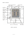
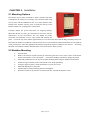
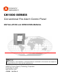
CK1000 SERIES
Conventional Fire Alarm Control Panel
INSTALLATION and OPERATION MANUAL
NOTICE
All information, documentation, and specifications contained in this manual are subject to
change without prior notice by the manufacturer.
©2000 by Convoy Security Technology Corporation
Printed April 12, 2008
MCK1000V3.6.PDF
CK1000 Ver3 Rev.6
Fire Alarm System Limitations
While a fire alarm system may lower insurance
rates, it is not a substitute for fire insurance!
An automatic fire alarm system–typically made up of
smoke detectors, heat detectors, manual pull stations,
audible warning devices, and a fire alarm control with
remote notification capability–can provide early warning of
a developing fire.
Such a system, however, does not assure protection
against property damage or loss of life resulting from a
fire.
The Manufacturer recommends that smoke and/or heat
detectors be located throughout a protected premise
following the recommendations of the current edition of
the National Fire Protection Association Standard 72
(NFPA 72), manufacturer's recommendations, State and
local codes, and the recommendations contained in the
Guide for Proper Use of System Smoke Detectors, which
is made available at no charge to all installing dealers. A
study by the Federal Emergency Management Agency
(an agency of the United States government) indicated
that smoke detectors may not go off in as many as 35% of
all fires. While fire alarm systems are designed to
provide early warning against fire, they do not guarantee
warning or protection against fire. A fire alarm system
may not provide timely or adequate warning, or simply
may not function, for a variety of reasons:
Smoke detectors may not sense fire where smoke
cannot reach the detectors such as in chimneys, in or
behind walls, on roofs, or on the other side of closed
doors. Smoke detectors also may not sense a fire on
another level or floor of a building. A second-floor
detector, for example, may not sense a first-floor or
basement fire.
Particles of combustion or "smoke" from a developing
fire may not reach the sensing chambers of smoke
detectors be- cause:
l
Barriers such as closed or partially closed doors, walls,
or chimneys may inhibit particle or smoke flow.
l
Smoke particles may become "cold," stratify, and not
reach the ceiling or upper walls where detectors are
located.
l
Smoke particles may be blown away from detectors by
air outlets.
l
Smoke particles may be drawn into air returns before
reaching the detector.
The amount of "smoke" present may be insufficient to
alarm smoke detectors. Smoke detectors are designed
to alarm at various levels of smoke density. If such
density levels are not created by a developing fire at the
location of detectors, the detectors will not go into alarm.
Smoke detectors, even when working properly, have
sensing limitations. Detectors that have photo electronic
sensing chambers tend to detect smoldering fires better
Telephone lines needed to transmit alarm signals from a
premise to a central monitoring station may be out of
service or temporarily disabled. For added protection
against telephone line failure, backup radio transmission
systems are recommended.
The most common cause of fire alarm malfunction is
inadequate maintenance. To keep the entire fire alarm
system in excellent working order, ongoing maintenance
is required per the manufacturer's recommendations, and
UL and NFPA standards.
At a minimum, the
than flaming fires, which have little visible smoke.
Detectors that have ionizing-type sensing chambers tend
to detect fast-flaming fires better than smoldering fires.
Because fires develop in different ways and are often
unpredictable in their growth, neither type of detector is
necessarily best and a given type of detector may not
provide adequate warning of a fire.
Smoke detectors cannot be expected to provide adequate
warning of fires caused by arson, children playing with
matches (especially in bedrooms), smoking in bed, and
violent explosions (caused by escaping gas, improper
storage of flammable materials, etc.).
Heat detectors do not sense particles of combustion and
alarm only when heat on their sensors increases at a
predetermined rate or reaches a predetermined level.
Rate-of-rise heat detectors may be subject to reduced
sensitivity over time. For this reason, the rate-of-rise
feature of each detector should be tested at least once per
year by a qualified fire protection specialist. Heat
detectors are designed to protect property, not life.
IMPORTANT! Smoke detectors must be installed in
the same room as the control panel and in rooms used by
the system for the connection of alarm transmission wiring,
communications, signaling, and/or power. If detectors
are not so located, a developing fire may damage the
alarm system, crippling its ability to report a fire.
Audible warning devices such as bells may not alert
people if these devices are located on the other side of
closed or partly open doors or are located on another floor
of a building. Any warning device may fail to alert people
with a disability or those who have recently consumed
drugs, alcohol or medication. Please note that:
l
Strobes can, under certain circumstances, cause
seizures in people with conditions such as epilepsy.
l
Studies have shown that certain people, even when
they hear a fire alarm signal, do not respond or
comprehend the meaning of the signal. It is the
property owner's responsibility to conduct fire drills
and other training exercise to make people aware of
fire alarm signals and instruct them on the proper
reaction to alarm signals.
l
In rare instances, the sounding of a warning device
can cause temporary or permanent hearing loss.
A fire alarm system will not operate without any electrical
power. If AC power fails, the system will operate from
standby batteries only for a specified time and only if the
batteries have been properly maintained and replaced
regularly.
Equipment used in the system may not be technically
compatible with the control. It is essential to use only
equipment listed for service with your control panel.
requirements of Chapter 7 of NFPA 72 shall be followed.
Environments with large amounts of dust, dirt or high air
velocity require more frequent maintenance.
A
maintenance agreement should be arranged through the
local manufacturer's representative.
Maintenance
should be scheduled monthly or as required by National
and/ or local fire codes and should be performed by
authorized professional fire alarm installers only.
Adequate written records of all inspections should be
kept.
Installation Precautions
Adherence to the following will aid in problem-free
installation with long-term reliability:
WARNING - Several different sources of power can be
connected to the fire alarm control panel. Disconnect all
sources of power before servicing. Control unit and
associated equipment may be damaged by removing
and/or inserting cards, modules, or interconnecting cables
while the unit is energized. Do not attempt to install,
service, or operate this unit until this manual is read and
understood.
CAUTION - System Reacceptance Test after Software
Changes. To ensure proper system operation, this
product must be tested in accordance with NFPA 72
Chapter 7 after any programming operation or change in
site-specific soft- ware. Reacceptance testing is required
after any change, addition or deletion of system
components, or after any modification, repair or
adjustment to system hardware or wiring.
All components, circuits, system operations, or software
functions known to be affected by a change must be
100% tested. In addition, to ensure that other operations
are not inadvertently affected, at least 10% of initiating
devices that are not directly affected by the change, up to
a maximum of 50 de- vices, must also be tested and
proper system operation verified.
This system meets NFPA requirements for operation at
0-49° C/32-120° F and at a relative humidity of 85% RH
(non- condensing) at 30° C/86° F. However, the useful
life of the system's standby batteries and the electronic
components may be adversely affected by extreme
temperature ranges and humidity. Therefore, it is
recommended that this system and all peripherals be
installed in an environment with a nominal room
temperature of 15-27° C/60-80° F.
Verify that wire sizes are adequate for all initiating and
indicating device loops. Most devices cannot tolerate
more than a 10% I.R. drop from the specified device
voltage.
Like all solid state electronic devices, this system may
operate erratically or can be damaged when subjected to
lightning-induced transients. Although no system is
completely immune from lightning transients and
interferences, proper grounding will reduce susceptibility.
Overhead or outside aerial wiring is not recommended,
due to an increased susceptibility to nearby lightning
strikes. Consult with the Technical Services Department
if any problems are anticipated or encountered.
Disconnect AC power and batteries prior to removing or
inserting circuit boards. Failure to do so can damage
circuits.
Remove all electronic assemblies prior to any drilling,
filing, reaming, or punching of the enclosure. When
possible, make all cable entries from the sides or rear.
Before making modifications, verify that they will not
interfere with battery, transformer, and printed circuit
board location.
Do not tighten screw terminals more than 9 in-lbs.
Over-tightening may damage threads, resulting in
reduced terminal contact pressure and difficulty with
screw terminal removal.
Though designed to last many years, system
components can fail at any time. This system contains
static-sensitive components. Always ground yourself
with a proper wrist strap before handling any circuits so
that static charges are re- moved from the body. Use
static-suppressive packaging to protect electronic
assemblies removed from the unit.
Follow the instructions in the installation, operating, and
programming manuals.
These instructions must be
followed to avoid damage to the control panel and
associated equipment. FACP operation and reliability
depend upon proper installation by authorized personnel.
FCC Warning
WARNING: This equipment generates, uses, and can
radiate radio frequency energy and if not installed and
used in accordance with the instruction manual, may
cause interference to radio communications. It has been
tested and found to comply with the limits for class A
computing device pursuant to Subpart B of Part 15 of FCC
Rules, which is designed to provide reasonable protection
against such interference when operated in a commercial
environment. Operation of this equipment in
a residential area is likely to cause interference, in which
case the user will be required to correct the interference
at his own expense.
Canadian Requirements
This digital apparatus does not exceed the Class A
limits for radiation noise emissions from digital
apparatus set out in the Radio Interference Regulations of
the Canadian Department of Communications.
Le present appareil numerique n'emet pas de bruits
radioelectriques depassant les limites applicables aux
appareils numeriques de la classe A prescrites dans le
Reglement sur le brouillage radioelectrique edicte par le
ministere des Communications du Canada.
Notes
Table of Contents
CHAPTER 1: Product Description.............................................................................................................................7
1.1 Product Features .....................................................................................................................................7
1.2 Specifications...........................................................................................................................................9
1.3 Controls and Indicators.........................................................................................................................9
1.4 Circuits ....................................................................................................................................................13
CHAPTER 2: Installation ......................................................................................................................................15
2.1 Mounting Options .................................................................................................................................15
2.2 Backbox Mounting................................................................................................................................15
2.3 Operating Power ...................................................................................................................................16
2.4 Input Circuits..........................................................................................................................................18
2.5 Output Circuits ......................................................................................................................................19
2.6 Power-limited Wiring Requirements ................................................................................................20
CHAPTER 3: Programming Instructions..........................................................................................................21
3.1 Switch Functions ..................................................................................................................................21
3.2 Entering Program Mode ......................................................................................................................21
3.3 Programming Functions .....................................................................................................................21
3.4 Activate Sound Output ........................................................................................................................21
3.5 Zone Disable...........................................................................................................................................22
3.6 Sound Disable........................................................................................................................................22
3.7 Manual / Automatic running mode switch......................................................................................22
3.8 Zone Input mode selection.................................................................................................................22
CHAPTER 4: Operating Instructions..................................................................................................................23
4.1 Switch Functions in Normal Mode ...................................................................................................23
4.2 Status LEDs............................................................................................................................................24
4.3 Operation ................................................................................................................................................25
4.3.1 Fire Alarm Response ................................................................................................................26
4.3.2 Fire Alarm Restoral....................................................................................................................26
4.3.3 System Supervisory Condition Response ..........................................................................26
4.3.4 System Supervisory Restoral Response.............................................................................26
4.3.5 Fault Condition Response.......................................................................................................26
4.3.6 Fault Condition Restoral..........................................................................................................26
Appendix A
Battery Calculations ....................................................................................................................27
Appendix B
Wire Requirements.......................................................................................................................29
Limited Warranty...................................................................................................................................................30
CK1000 Main Circuit Board
CK1000 Terminals and Connectors
Page 6 of 30
CHAPTER 1:
Product Description
The CK1000 is a 4-zone to 16-zone FACP (Fire Alarm Control Panel), which uses conventional input devices.
The panel accepts water flow devices, two-wire smoke detectors, four-wire smoke detectors, pull stations and
other normally-open contact devices. Outputs include four Notification Appliance Circuits (NAC, SOUND1-4),
three standard Form-A relays (alarm, trouble and supervisory) and an EIA-485 port to interface with remote
annunciators and optional remote relay modules. The FACP is field programmable via the panel keypad. It also
supervises all wiring, AC voltage and battery level.
This series of panels are basically the same in application and operation, their differences are shown in Table 1-1.
CK1000 will be described as the example in the following sections.
FACP
Number of Detection Zones
Table 1-1
Number of Sounder Outputs
CK1004
4
1
N/A
CK1008
8
2
N/A
CK1016
16
4
N/A
Output Delay Settings
1.1 Product Features
l
4,8,16 Class B Initiating Device Circuits (IDCs)
✓ All zones accept conventional detectors and any normally open contact device
l
Four Class B Notification Appliance Circuits (NACs)
l
One Form-A Alarm Relay
l
One Form-A Trouble Relay
l
One Form-A Supervisory Relay
l
3.0 amps of system power
l
Max 20 conventional detectors in one zone.
l
Auto/Manual mode setting enable walk test.
l
Each Zone can be disabled,
l
Sound output can be disabled.
l
Manual active sound output enabled.
l
Able to report short and broken circuit of detection zones.
l
Designed with standby batteries and space provision for two sealed lead-acid batteries.
l
Testing and disable functions.
Page 7 of 30
FIGURE 1.1: CK1000 Panel
FIGURE 1-1: CK1000 Panel
Page 8 of 30
1.2 Specifications
AC Power
220 VAC, 50 Hz, 2.3 amps
Wire size: minimum #14 AWG (2.0 mm2) with 600V insulation
Battery (lead acid only)
Maximum Charging Circuit: Normal Flat Charge—27.6V @ 0.8 amp
Maximum Charger Capacity: 18 Amp Hour batter
Sound Output Device Circuits
General Alarm Zones 1 through 16
Operation: All zones Class B
Normal Operating Voltage: Nominal 24 VDC (ripple = 100 mV maximum)
Alarm Current: 15 mA threshold
Short Circuit Current: 42 mA maximum
Maximum Loop Resistance: 100 ohms
End-of-Line Resistor: 4.7K, ½ watt
Detector Loop Current is sufficient to ensure operation of two alarmed detectors per zone
Standby Current: 7.26 mA
Three Relays Output
Relay contact rating: 2.0 amps @ 30 VDC (resistive), 2.0 amps @ 30 VAC (resistive)
Nonresettable 24 VDC Power
Maximum ripple voltage: 10 mVRMS
Operating Voltage nominal 24 volts
Total DC current available from this output is up to 500 mA
Recommended maximum Standby current is 150 mA
1.3 Controls and Indicators
Front Panel Keys in Normal Mode
l
Silence
l
Mute
l
Test/é
l
Reset/ê
l
Mode
LEDs
l
l
l
l
l
l
l
l
l
l
l
AC Power - green or yellow LED
Battery - green or yellow LED
Mute - yellow LED
Silence - yellow LED
Fire Alarm - red LED
Fault - yellow LED
Supervisory - red LED
Activate - red LED
Zone Disabled - yellow LED
Sound Disabled - yellow LED
NAC Fault - yellow LED
Page 9 of 30
l
l
l
l
l
l
Manual - red LED
Automatic - red LED
Sound1 to 4 - red LED or yellow LED
Zone Fire Alarm - red LED
Zone Fault Alarm - yellow LED
Ground Fault - yellow LED
FIGURE 1.3.1: CK1004 LEDs and Keypad
Page 10 of 30
FIGURE 1.3.2: CK1008 LEDs and Keypad
Page 11 of 30
FIGURE 1.3.3: CK1016 LEDs and Keypad
Page 12 of 30
Local Sounder
A piezo sounder provides separate and distinct sounds for alarm, trouble and supervisory conditions:
l
Alarm - pulse ½ second On and ½ second OFF
l
Fault - pulse 1½ second On and 1½ second Off
l
Supervisory - pulse ½ second On and ½ second OFF
1.4 Circuits
Input Circuits
Sixteen input circuits provide configuration. Input circuits 1 through 16 may be used as standard fire alarm
control panel zones. All sixteen Initiating Device Circuits accept normally-open contact devices and
two-wire smoke detectors.
Output Circuits
•
24 Volt Resettable Power Output 1000 mA
•
24 Volt Nonresettable Power Output 1000 mA
•
24 Volt Battery Charger (up to 18 AH batteries)
•
EIA-485 Port (interfaces to Annunciators, and Graphic Annunciators and Remote Relay Module)
Sound (Notification Appliance )Circuits
Four Notification Appliance Circuits.
Relays
Three dry relays for system alarm, system trouble and supervisory are provided standard. Contacts are rated
2.0 amps @ 30 VDC (resistive) and 2.0 amps @ 30 VAC (resistive).
EIA-485 Port
EIA-485 compatible port supports up to 10 different device addresses which can consist of Remote
Annunciators, Relay Modules, Annunciators or Graphic Annunciators or any combination of the four modules.
Battery Charger
Battery Charger will charge up to 18 AH batteries. The CK1000 cabinet holds a maximum of 7 AH batteries.
The external box is required to hold 18 AH batteries. The charger is rated for 500 mA maximum current.
Page 13 of 30
1.5 Components
Main Circuit Board
The main circuit board contains the system's CPU, power supply, other primary components and wiring interface
connectors. Optional modules plug in and are mounted to the main circuit board. The main circuit board is
delivered pre-mounted in the cabinet.
Cabinet
The cabinet is red and the backbox measures 13.78" (35 cm) long X 15.75" (40 cm) high X 6.50"(16.5cm) deep and
provides space for two batteries (up to 7 Amp Hours).
Power Module Assembly
One 75VA power module is provided standard with the panel.
Batteries
The cabinet provides space for 7 Amp Hour batteries (larger batteries up to 18 Amp Hour batteries, use the external
battery box).
Batteries must be ordered separately.
Page 14 of 30
CHAPTER 2:
Installation
2.1 Mounting Options
The cabinet may be either semi-flush or surface mounted. The door
is attached to the cabinet by two hinges. The cabinet mounts using
two key slots and one additional 0.250" (6.35 mm) diameter holes
located in the backbox. The key slots are located at the top of the
backbox and the one securing holes at the bottom.
Carefully unpack the system and check for shipping damage.
Mount the cabinet in a clean, dry, vibration-free area where extreme
temperatures are not encountered. The area should be readily
accessible with sufficient room to easily install and maintain the
panel. Locate the top of the cabinet approximately five feet above the floor with the hinge mounting on the left.
Determine the number of conductors required for the devices to be installed. Sufficient knockouts are provided for
wiring convenience. Select the appropriate knockout(s) and pull the required conductors into the box. All wiring
should be in accordance with the National and/or Local codes for fire alarm systems.
2.2 Backbox Mounting
✓
✓
✓
✓
✓
✓
✓
✓
Open the door.
Remove the main PC board assembly by unscrewing the four screws in the corners of the board.
Set the board aside in a safe, clean place. Avoid static discharge which may damage the board.
Mark and predrill holes for the top two keyhole mounting bolts using the dimensions illustrated.
Install two upper fasteners in the wall with the screw heads protruding.
Using the upper 'keyholes', mount the backbox over the two screws.
Mark and drill the lower one holes.
Mount backbox, install remaining fasteners and tighten.
When the location is dry and free of construction dust, reinstall the main PC board.
Page 15 of 30
Draw wires through the respective knockout locations.
FIGURE 2-2: Cabinet Dimensions and Knockout Locations
2.3 Operating Power
WARNING: Several different sources of power can be connected to this panel. Disconnect all sources of power
before servicing. The panel and associated equipment may be damaged by removing and/or inserting cards,
modules or interconnecting cables while this unit is energized.
Primary Power Source (AC) and Earth Ground Connections
AC power connections are made inside the control panel cabinet. The primary power source for the CK1000 is
220 VAC, 50 Hz, 2.3 amps. Run a pair of wires (with ground conductor) from the protected premises main
breaker box to AC Power Terminal of the main circuit board. As per the Canadian Electrical Code, use 14 AWG
(2.00 mm2, 1.6 mm O.D.) or heavier gauge wire with 600V insulation. No other equipment may be connected to
this circuit. In addition, this circuit must be provided with overcurrent protection and may not contain any power
disconnect devices. A separate Earth Ground connection must be made to ensure proper panel operation and
lightning and transient protection. Connect the Earth Ground wire [minimum 14 AWG (2.00 mm2)] to the
mounting stud located on the cabinet.
Do not use conduit for the Earth Ground connection since this does not provide reliable protection.
Secondary Power Source (Batteries)
Observe polarity when connecting the battery. Connect the battery cable to Battery Terminal on the main circuit
board using the plug-in connector and cable provided. The battery charger is current-limited and capable of
Page 16 of 30
recharging sealed lead acid type batteries. The charger shuts off when the system is in alarm. See “Battery
Calculations” on page 27 for calculation of the correct battery rating.
WARNING: Battery contains sulfuric acid which can cause severe burns to the skin and eyes and can destroy
fabrics. If contact is made with sulfuric acid, immediately flush the skin or eyes with water for 15 minutes and
seek immediate medical attention.
FIGURE 2-3: Typical Operating Power Connections
Page 17 of 30
2.4 Input Circuits
The control panel has 4-16 zone input circuits. The maximum loop resistance limit for each input circuit is 100
ohms. All field wiring of each zone is supervised for opens and ground faults. Both conditions are visually and
audibly annunciated.
Each zone is a Initiating Device Circuit (IDC) designed to accept any normally-open contact devices and
conventional 2-wire, 24 volt smoke detectors.
All zones may be configured for general fire alarm applications.
Four-wire smoke detectors may be connected to any zone. Resettable power is provided via RESETABEL DC24V
Terminal. Refer to the Device Compatibility Document for a list of compatible smoke detectors.
It is allowable to mix an assortment of device types (i.e. smoke detectors, heat detectors, pull stations, etc.) on any
zone.
FIGURE 2-4-1: Class B Initiating Device Circuit Connections
FIGURE 2-4-2: Supervisory Input Circuit Connections
Any switch or push button can be connected in supervisory
terminal IN1, IN2.
When terminal IN1, IN2 has the DC12 voltage, the panel
Supervisory LED turns on to indicate that there is a supervisory
alarm.
Page 18 of 30
2.5 Output Circuits
DC Power Output Connections
FIGURE 2-5-1: Auxiliary Power Connections
Nonresettable Power (1000 mA) 24 VDC
filtered, nonresettable power can be obtained
from Terminals 1(+) and 2(-).
4-Wire Smoke Detector Power (1000 mA) 24VDC
filtered, resettable power for 4-wire smoke detectors can
be obtained from Terminals 3(+) and 4(-)
Notification Appliance Circuits
The CK1000 provides 1-4 Notification Appliance Circuits standard. Each circuit is capable of 2.5 amps of
current. Total current drawn from these as well as other DC power outputs cannot exceed 3.0 amps with the
standard transformer. Circuits are supervised.
FIGURE 2-5-2: Notification Appliance Circuit Connections
Page 19 of 30
Standard Relays
The control panel provides three relays rated for 2.0 amps @ 30 VDC (resistive) and 2.0 amps @ 30
VAC(resistive).
FIGURE 2-5-3: Relay Terminals
Relay connections may be power-limited or nonpower-limited, provided that a minimum of 0.25" is maintained
between conductors of power-limited and nonpower-limited circuits.
2.6 Power-limited Wiring Requirements
Power-limited and nonpower-limited circuit wiring must remain separated in the cabinet. All power-limited
circuit wiring must remain at least 0.25" (6.35 mm) away from any nonpower-limited circuit wiring.
Furthermore, all power-limited and nonpower-limited circuit wiring must enter and exit the cabinet through
different knockouts and/or conduits. A typical wiring diagram for the CK1000 is illustrated in Figure 2-3.
Page 20 of 30
CHAPTER 3:
Programming Instructions
This chapter describes programming the CK1000 from the onboard keypad. Programming can be performed only
by a factory authorized representative. Control panel programming is possible at any time except when an alarm
or zone fault condition is present or during a fire test.
All programming selections are stored in nonvolatile Electrically-Erasable Programmable Read-Only Memory
(EEPROM). This ensures that the control panel will remember all entries made in programming mode even if both
AC and battery power are removed.
The control panel comes with factory chosen options already programmed. Other options may be programmed if
desired. If all factory default settings are acceptable, programming is complete.
Successful entry into Program Mode from the keypad shuts off the fire protection and causes the all other LED
turn off except the relative function programming LED.
3.1 Switch Functions
The function of each key in Program Mode is illustrated below:
FIGURE 3-1: Programming Mode Keypad
3.2 Entering Program Mode
To enter program mode, the Mode key must be pressed and held for more than three seconds (time to prevent
accidental activation).
Once in Programming Mode, the control panel will:
✓ The piezo sounder beep twice
✓ Blink the Activate LED upon first entering Program Mode
✓ Turn off all other LEDs
3.3 Programming Functions
There are four features can be programmed as below:
l
Manual Activate Sound 1-4 Output directly
l
Disable Zone1-16
l
Disable Sound 1-4
l
Switch panel running mode in manual and automatic.
3.4 Activate Sound Output
1. Press and held Mode key for more than three seconds until the Activate LED blinks.
2. Press “Enter (Mode)” key to enter Activate menu.
3. Press “Up” and “Down” arrow key to select Sound1 to Sound4, the selected Sound LED blinks.
Page 21 of 30
3. Press “Enter (Mode)” key to activate Sound output. The corresponding relay is activated.
3.5 Zone Disable
1. Press and held Mode key for more than three seconds until the Activate LED blinks.
2. Press “Up” and “Down” arrow key to select Zone Disable LED blinks.
3. Press “Enter (Mode)” key to enter Zone Disable menu.
3. Press “Up” and “Down” arrow key to select Zone1 to Zone16, the selected Zone LED blinks.
4. Press “Enter (Mode)” key to disable the corresponding zone. Then panel will be reset automatically.
5. After reset automatically, the disabled Zone Yellow LED turns on, and the Zone Disable LED turns on.
3.6 Sound Disable
1. Press and held Mode key for more than three seconds until the Activate LED blinks.
2. Press “Up” and “Down” arrow key to select Sound Disable LED blinks.
3. Press “Enter (Mode)” key to enter Sound Disable menu.
4. Press “Up” and “Down” arrow key to select Sound1 to 4, the selected Sound LED blinks.
5. Press “Enter (Mode)” key to disable the corresponding sound. Then panel will be reset automatically.
6. After reset automatically, the disabled Zone Yellow LED turns on, and the Zone Disable LED turns on.
3.7 Manual / Automatic running mode switch
1. Press and held Mode key for more than three seconds until the Activate LED blinks.
2. Press “Up” and “Down” arrow key to select Manual or Automatic LED blinks.
2. Press “Enter (Mode)” key to set panel running mode.
In program mode, press “Cancel (Silence”) key to exit the program mode in any time.
A pause of up to 30 seconds is allowed between each key press, otherwise the panel will exit program mode
anyway.
3.8 Zone Input mode selection
There is one jump J2 on the right bottom of main PCB board,
1. Short the terminal 1, 2, all zone input short circuit indicate the fault event.
2. Short the terminal 2, 3, all zone input short circuit indicate the alarm event.
Page 22 of 30
CHAPTER 4:
Operating Instructions
FIGURE 4-1: LED Indicators and Keypad
The CK1000 has two modes of operation which are Normal, Program.
Upon initial power-up, the system will be in Normal Mode. This section discusses operation of the control panel
in the Normal Mode.
4.1 Switch Functions in Normal Mode
Silence
A Silence key is located on the CK1000 keypad (illustrated in Figure 4-1).
If Silence keys is pressed, the following will occur:
✓ The silenceable Notification Appliance Circuits (Sound1-Sound 4 Output) will be turned OFF.
✓ The corresponding Sound LED will be turned OFF
✓ The main circuit board signal Silence LED will be turned ON
Upon the occurrence of a subsequent event (alarm or trouble), signal Silence is overridden and the control
panel will respond to the new event.
Mute
An Mute key is located on the CK1000 keypad (refer to Figure 4-1), The Mute key silences the system
piezo sounders and changes all flashing system LEDs to steady. Pressing the Mute key will have no effect
on the Notification Appliance Circuits.
Test
If the Test key is pressed, the CK1000 will perform a Lamp Test, All panel LEDs will be turned on and the
piezo will sound.
Page 23 of 30
Reset
The System Reset key resets the system and any detectors. A Reset key is located on the CK1000 keypad
(illustrated in Figure 4-1). If the System Reset keys are pressed, the control panel will:
✓ Clear the status LEDs
✓ Turn off the Notification Appliance Circuits
✓ Reset all zones by temporarily removing power
✓ Silence the onboard piezo sounder
✓ Restore all system relays to normal
✓ Temporarily remove power from the resettable power output Terminals
Any alarm, supervisory or fault condition that exists after a system reset will resound the system,
reactivating normal system activity. Any zones and sounds that were disabled before the reset will remain
disabled after the reset, the panel running mode will remain the same after the reset..
4.2 Status LEDs
AC Power LED
A green LED that remains on while the AC power supply is within correct limits. A yellow LED blinks under
Battery powered condition. It turns on steady when Mute key is pressed. If this indicator fails to light under
normal conditions, service the system immediately.
Battery LED
A green LED that remains on while the Battery power supply is within correct limits. A yellow LED that
blinks is to indicate a low battery or no battery condition on the CK1000. It turns on steady when Mute key is
pressed. If this indicator fails to light under normal conditions, service the system immediately.
Mute LED
A yellow LED that turns on to indicate that an Alarm or Fault condition exists in the system, but piezo
sounder have been silenced.
Silence LED
A yellow LED that turns on to indicate that an Alarm condition exists in the system, but Notification
Appliance Circuits have been silenced.
Fire Alarm LED
A red LED that turn on when a system fire alarm condition is detected.
Fault LED
A yellow LED that turn on to indicate that a system fault or abnormal condition exists and that the fire alarm
system may be inoperative. It turns on steady when a signal Silence or Mute key is pressed.
Supervisory LED
A red LED that turn on to indicate the need for action in connection with the supervision or maintenance of
sprinklers, extinguishing systems or other protective systems that connected in Supervisory Terminal.
Activate LED
A red LED that flashes when enter the directly activate mode. In this mode, the Notification Appliance
Circuits (Sound1-Sound 4 Output) can be activated directly by manual. A red LED that turn on to indicate any
of sound1 to sound 4 has been activated.
Zone Disabled LED
A yellow LED that turn on to indicate that one or more alarm zones have been disabled. The disabled zone(s)
fault LED will also be on. When enter program mode, a flash LED indicates the program features.
Sound Disabled LED
A yellow LED that turn on to indicate that one or more Notification Appliance Circuits (Sound1-Sound 4
Page 24 of 30
Output) have been disabled. The disabled Sound(s) yellow LED will also be on. When enter program mode,
a flash LED indicates the program features.
Manual LED
A red LED that turn on to indicate that the panel is running in manual mode. In manual mode, All Notification
Appliance Circuits (Sound1-Sound 4 Output) have been disabled, but Sound1-Sound 4 Output can be
activated by manual.
Automatic LED
A green LED that turn on to indicate that the panel is running in automatic mode. In automatic mode, All
Notification Appliance Circuits (Sound1-Sound 4 Output) have been enabled that can be activated by Zone
alarms.
l
Zone1-Zone4 activates Sound1.
l
Zone5-Zone8 activates Sound2.
l
Zone9-Zone12 activates Sound3.
l
Zone13-Zone16 activates Sound4.
Sound1-4 LED
A red LED that turn on to indicate that the corresponding Notification Appliance Circuits (Sound1-Sound 4
Output) is be activated. A yellow LED that turn on to indicate that the corresponding Notification Appliance
Circuits (Sound1-Sound 4 Output) have been disabled or has some fault.
Zone 1 through Zone 16 Alarm LED
Red LEDs that blink to indicate that an alarm exists on the corresponding zone. It turns on steady when
Mute key is pressed.
Zone 1 through Zone 16 Fault LED
Yellow LEDs that blink to indicate that a fault or abnormal condition exist on the corresponding zone. It turns
on steady when Mute key is pressed.
LEDs on Main PCB board:
Charger LED
A green LED that remains on while the batteries has been charging by AC power.
Ground Fault LED
A yellow LED that remains on while the panel has earth fault.
System Fault LED
A yellow LED that remains on while the panel has some fault.
4.3 Operation
Normal Mode is the standard mode of operation. In this mode, the panel continuously monitors system status.
The Notification Appliance Circuits will be off, all relays are in their normal state and the onboard piezo sounder
will be off.
All alarm and system fault conditions are annunciated on the control panel's LEDs. The control panel will
maintain a 'last event list' which will consist of all alarms, supervisory alarms and system faults currently active
and not cleared, requiring immediate service. When the system is cleared and restored to normal, the LEDs will
be off except for the AC Power LED and Battery LED and status LEDs.
Higher priority events take precedence over lower priority events. Display and reporting of System Status is
done on a priority basis. Priorities are, from highest to lowest:
1. Alarms
2. Supervisory Alarms
Page 25 of 30
3.
System Faults
4.3.1 Fire Alarm Response
The control panel will, upon detection of an alarm condition, cause the following:
l
Turn on the system Alarm LED
l
Blink the Zone Alarm Red LED (½ second On, ½ second Off)
l
Turn the Notification Appliance Circuits on
l
Turn the piezo sounder on steady
l
Turn on alarm relay
4.3.2 Fire Alarm Restoral
The control panel returns to normal after all alarms have been cleared and a system reset key has been pressed
(pull stations have been reset, smoke detectors have reset and no smoke is present, waterflow has stopped). The
control panel will perform the following upon restoral of all active alarms:
l
Turn off the alarm LED
l
Turn off the Zone Alarm LED
l
Turn off the Notification Appliance Circuits
l
Turn off the piezo sounder
l
Turn off appropriate zone relay output
l
Turn off alarm relay
4.3.3 System Supervisory Condition Response
These Supervisory zones can be for supervisory in applications where a waterflow sensing device has been
employed and the wiring to the waterflow valve and/or a tamper switch is to be monitored. If the tamper switch
has been activated (normally open contacts close), a supervisory alarm condition will occur.
When a supervisory condition occurs, the control panel will cause the following:
l
Turn on the supervisory LED
l
Pulse system piezo sounders (½ second On, ½ second Off)
l
Turn on supervisory relay
4.3.4 System Supervisory Restoral Response
When the supervisory condition has been cleared and the reset key has been pressed, the control panel will
perform the following:
l
Turn off the supervisory LED
l
Shut off system piezo sounders
l
Turn off supervisory relay
4.3.5 Fault Condition Response
The control panel will perform the following upon detection of one or more fault conditions:
l
Turn on the trouble LED
l
Blink the Zone fault LED if fault condition is on the zone (½ second On, ½ second Off)
l
Activate fault relay
l
Sound system piezo sounders at a rate of 1½ second On, 1½ second Off
4.3.6 Fault Condition Restoral
The control panel performs the following upon restoral of all trouble conditions:
l
Shut off the fault LED
l
Shut off the zone fault LED(s)
l
Shut off the piezo sounder
l
Deactivate the fault relay
Page 26 of 30
Appendix A Battery Calculations
Use the Total Standby and Alarm Load Currents calculated in Table A-2 and Table A-3 for the following battery
calculation.
TABLE A-1: Battery Calculation
Standby Load
Required Standby Time in Hours
Current (amps)
X
(24 or 60 Hours)
[
]
[
]
Alarm Load
Current (amps)
[
]
=
Required Alarm Time in Hours
(i.e. 5 min. = 0.084 hours)
[
]
=
Add Standby and Alarm Load for Required Ampere Hour Battery
=
X
Multiply by derating factor of 1.2
X1.2
Note:
1.
2.
7 Ampere Hour battery can be located in the backbox.
Batteries larger than 7 Ampere Hour, up to 18 Ampere Hour, require the External battery box.
Page 27 of 30
A.1 Main Power Supply
The CK1000 provides filtered power for operating the fire alarm control panel, operating external devices and
operating the standby battery. The power for operating external devices is limited. Use Table A-2 (standby or
non-alarm) and Table A-3 (alarm) to determine if external loading is within the capabilities of the power supply.
TABLE A-2: Filtered Load in Standby @24 VDC.
Device Type
# of
Devices
Current
(amps)
Main Circuit Board
1
2-wire Detector Heads
[
]
4-wire Detector Heads
[
]
2
Power Supervision Relays [
]
Current Draw from DC24V
(nonalarm3)
X
X
X
X
Total Current
(amps)
0.08
[ ]1
[ ]1
0.025
=
0.08
=
=
=
=
Sum Column for Standby Load
=
amps
1. Refer to the Device Compatibility Document for 2-wire smoke detector standby current.
2. Must use compatible listed Power Supervision Relay.
3. The total standby current must include both the resettable and nonresettable DC24 output.. Caution must be
taken to ensure that current drawn from these outputs during alarm does not exceed maximum ratings specified
(see Table A-2).
TABLE A-3: Filtered Load in Alarm @24 VDC .
Device Type
# of
Devices
Main Circuit Board
1
2
4-wire Smoke Detector
[
]
3
Power Supervision Relay
[
]
4
Notification Appliances
[
]
Notification Appliances
[ ]
Current Draw from DC24V (alarm current)
Current
(amps)
X
X
X
X
x
0.138
[
]
0.025
[ ]
[ ]
Total Current
(amps)
=
=
=
=
=
=
0.1381
Sum Column for Standby Load5
=
amps
1. The current shown represents one zone on the Main Circuit Board in alarm. For all zones in alarm, the current
draw increases to 0.590 amps.
2. Current limitations of terminals:
Nonresettable power :1.0 amps, filtered, 24 VDC +/-5%, 120 Hz ripple @ 10 mVRMS
Resettable power: 1.0 amps, filtered, 24 VDC +/-5%, 120 Hz ripple @ 10 mVRMS,
3. Must use compatible listed Power Supervision Relay
4. Current limitation of per Notification Appliance Circuit expandable to 1.25 amps.
5. Total current draw listed above cannot exceed 3.0 amps
Page 28 of 30
Appendix B Wire Requirements
Connecting external system accessories to the CK1000 main circuits must be carefully considered to ensure
proper operation. It is important to use the correct type of wire, wire gauge and wire run length per each CK1000
circuit. Reference the chart below to specify wire requirements and limitations for each CK1000.
TABLE B-1: Wire Requirements
CIRCUIT CONNECTIONS
WIRE REQUIREMENTS
CIRCUIT CONNECTIONS
CIRCUIT TYPE
WIRE REQUIREMENTS
CIRCUIT
WIRE TYPE AND
FUNCTION
LIMITATIONS
RECOMMENDED
MAX. DISTANCE
WIRE GUAGE
Feet (meters)
12 AWG (3.25 mm2) Belden 9583
WPW999
10,000 (3,000 m)
14 AWG (2.00 mm2) Belden 9581
Initiating Device
Connects to
Untwisted, unshielded wire
8,000 (2,400 m)
WPW995
Circuit
Initiating Devices
(Do not exceed 100 ohms)
4,875 (1,480 m)
16 AWG (1.30 mm2) Belden 9575
3,225 (975 m)
WPW991
18 AWG (0.75 mm2) Belden 9574
WPW975
Connects to
EIA-485
annunciator
modules and relay
module
24 VDC resettable,
nonresettable
Connects to
Twisted, shielded pair with a
characteristic impedance of
18 AWG (0.75 mm2)
120 ohms
No more than 1.2 volt drop
annunciators and allowed from supply source
other accessories
6,000 (1,800 m)
to end of any branch
Page 29 of 30
Distance limitation
set by 1.2 volt
12 AWG (3.25 mm2) - 18 AWG
maxi- mum line
(0.75 mm2)
drop
Limited Warranty
The manufacturer warrants its products to be free from defects in materials and workmanship for eighteen (12)
months from the date of manufacture, under normal use and service. Products are date-stamped at time of
manufacture. The sole and exclusive obligation of the manufacturer is to repair or replace, at its option, free of
charge for parts, any part which is defective in materials or workmanship under normal use and service. For
products not under the manufacturer's date-stamp control, the warranty is eighteen (12) months from date of
original purchase by the manufacturer's distributor unless the installation instructions or catalog sets forth a
shorter period, in which case the shorter period shall apply. This warranty is void if the product is altered,
repaired, or serviced by anyone other than the manufacturer or its authorized distributors, or if there is a failure to
maintain the products and systems in which they operate in a proper and workable manner. In case of defect,
secure a Return Material Authorization form from our customer service department. Return product,
transportation prepaid, to the manufacturer.
This writing constitutes the only warranty made by this manufacturer with respect to its products. The
manufacturer does not represent that its products will prevent any loss by fire or otherwise, or that its products
will in all cases provide the protection for which they are installed or intended. Buyer acknowledges that the
manufacturer is not an insurer and assumes no risk for loss or damages or the cost of any inconvenience,
transportation, damage, misuse, abuse, accident, or similar incident.
THE MANUFACTURER GIVES NO WARRANTY, EXPRESSED OR IMPLIED, OF
MERCHANTABILITY, FITNESS FOR ANY PARTICULAR PURPOSE, OR OTHERWISE WHICH
EXTEND BEYOND THE DESCRIPTION ON THE FACE HEREOF. UNDER NO CIRCUMSTANCES
SHALL THE MANUFACTURER BE LIABLE FOR ANY LOSS OF OR DAMAGE TO PROPERTY,
DIRECT, INCIDENTAL, OR CONSEQUENTIAL, ARISING OUT OF THE USE OF, OR INABILITY TO
USE THE MANUFACTURER'S PRODUCTS. FURTHERMORE, THE MANUFACTURER SHALL NOT
BE LIABLE FOR ANY PERSONAL INJURY OR DEATH WHICH MAY ARISE IN THE COURSE OF,
OR AS A RESULT OF, PERSONAL, COMMERCIAL, OR INDUSTRIAL USE OF ITS PRODUCTS.
This warranty replaces all previous warranties and is the only warranty made by the manufacturer. No increase or
alteration, written or verbal, of the obligation of this warranty is authorized.
Page 30 of 30