1
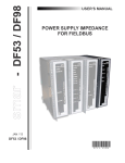
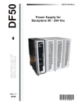
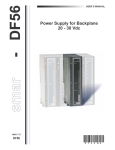
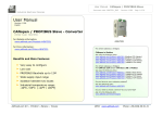
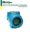
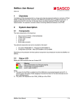
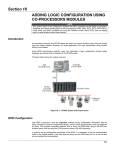
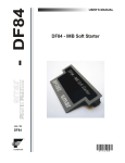
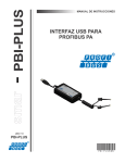
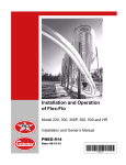
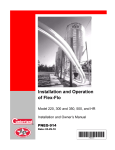
USER'S MANUAL
HIGH SPEED COUPLER
PROFIBUS DP/PA
HSC303
H S C 3 0 3 ME
smar
www.smar.com
Specifications and information are subject to change without notice.
Up-to-date address information is available on our website.
web: www.smar.com/contactus.asp
HSC303 – High Speed Coupler Profibus DP/PA
AVOIDING ELECTRICAL DISCHARGES
ATTENTION
Electrostatic discharges may damage semiconductor electronic components in printed circuit
boards. They usually occur when touching components or connector pins from modules and racks,
without wearing the appropriate equipment to prevent discharges. It is recommended to take the
following precautions:
•
Before handling modules and racks, remove the electrostatic charge from your body by
wearing a proper wristband or touching grounded devices;
•
Avoid touching electronic components or connector pins from racks and modules.
3
HSC303 – User’s Manual
TABLE OF CONTENTS
AVOIDING ELECTRICAL DISCHARGES............................................................................................................................................. 3
HSC303 – HIGH SPEED COUPLER PROFIBUS DP/PA ..................................................................................................................... 5
DESCRIPTION ................................................................................................................................................................................... 5
CHARACTERISTICS AND MODULE LIMITS .................................................................................................................................................. 5
ORDERING CODE ........................................................................................................................................................................................... 5
TECHNICAL SPECIFICATIONS ........................................................................................................................................................ 6
INDICATION LEDS........................................................................................................................................................................................... 7
INSTALLATION .................................................................................................................................................................................. 8
INSTALLING MODULES IN THE RACK .......................................................................................................................................................... 8
DIMENSIONAL DRAWING............................................................................................................................................................................... 9
USING THE HSC303-2 COUPLER .................................................................................................................................................... 9
USING THE HSC303-4 COUPLER .................................................................................................................................................. 11
APPLICATION SCENARIOS ............................................................................................................................................................ 14
SCENARIO 1 – DF50/HSC303/DF52/DF53 – UP TO 4 CHANNELS OF 340 MA/CHANNEL ...................................................................... 14
SCENARIO 2 – DF50/HSC303/DF52/DF98 – 2 CHANNELS OF UP TO 500 MA/CHANNEL ...................................................................... 15
SCENARIO 3 – DF50/HSC303/DF52/DF98/DF52/DF98 – UP TO 4 CHANNELS OF 500 MA/CHANNEL .................................................. 16
SCENARIO 4 – DF50/HSC303/DF52/DF47 – WITH INTRINSIC SAFETY BARRIER AND 1 PA CHANNEL .............................................. 17
SCENARIO 5 – DF50/HSC303/DF52/DF47/DF52/DF47 – WITH INTRINSIC SAFETY BARRIER AND UP TO 4 PA CHANNELS ............ 18
SCENARIO 6 – DF50/HSC303/DF52/DF53 – WITH LM153 (SIEMENS DP/PA LINK) ................................................................................ 19
APPENDIX A - SRF – SERVICE REQUEST FORM ......................................................................................................................... A.1
4
HSC303 – High Speed Coupler Profibus DP/PA
HSC303 – HIGH SPEED COUPLER
PROFIBUS DP/PA
Description
The Profibus DP/PA high speed coupler of Smar, HSC303, is a module whose function is to allow
access to Profibus PA devices via Profibus DP network.
Operating with baud rates from 9600 bps to 12 Mbps on Profibus DP network, the HSC303 works
seamlessly, requiring no additional configuration. It allows access of multiple masters to Profibus PA
devices, in addition to the separate use of one master for control and the other for asset
management or parameterization, when desired.
It does not have limit of devices per Profibus PA channel, being limited by the power supply and
impedance used to power the channel.
It accepts versions of Profibus DPV1 and DPV0 protocols.
Characteristics and Module Limits
•
•
•
•
One Profibus DP channel supporting up to 12 Mbps;
Two (HSC303-2) or four (HSC303-4) Profibus PA ports without logic limit of devices, being
limited by the power supply and impedance of the channel;
It supports up to 125 devices, using the 0-125 address range;
Automatically detects the baud rate.
Ordering Code
HSC303-2 – High speed coupler with 2 Profibus PA channels for connection to Profibus DP channel
HSC303-4 – High speed coupler with 4 Profibus PA channels for connection to Profibus DP channel
- PA1+
- PA4+
STB
- PA2+
STB
smar
- PA2+
- PA3+
P2
DP TERM.
ON
P4
P3
- PA1+
P1
~FAIL~
~FAIL~
ON
ON
DP TERM.
ON
P2
P1
SERIAL
NUMBER
High Speed Coupler
Profibus DP/4PA
HSC303-4
SERIAL
NUMBER
High Speed Coupler
Profibus DP/2PA
HSC303-2
smar
Figure 1 – HSC303-2 and HSC303-4
5
HSC303 – User’s Manual
Technical Specifications
Baud Rate
Standard
Physical layer
Connector
Number of channels
Communication rate
Standard
Physical layer
MAU Type
Insulation
PROFIBUS DP CHANNEL
From 9.6 Kbit/s up to 12 Mbits/s
EN 50170 and EN 50254
EIA RS-485
M12
PROFIBUS PA CHANNELS
HSC303-2: 2 channels
HSC303-4: 4 channels
31.25 kbps
EN 61158-2, EN 50170
ISA-S50.02-1992
Passive (not powered bus)
500 Vac
FAILURE RELAY
Output Type
Solid state relay, normally closed (NC), isolated
Maximum voltage
30 Vdc
Maximum current
200 mA
Overload protection
Does not have. It must be provided externally
Normal operation
Opened contacts
Failure condition
Closed contacts
Maximum cable length connected to the relay
30 m
The power supply for the load activated by the failure relay must not come from an external network
(outside the panel).
IMB BUS
5 Vdc
Yes
Voltage
Hot swap
Module Characteristics
FPGA
Storage Memory
Processor
Running Memory
Clock
Operation Voltage
PROCESSOR
Changes CycloneIII
4KB
NiosII
1MB
85 MHz
3.3 V for I/O, 2.5V for PLL, 1.2V for core and
5V for communication channels.
Power supply voltage
Typical current
Real consumption
Environment air temperature for operation
Storage temperature
Relative air humidity for operation
Cooling mode
Weight
Dimensions (H x W x D) in mm
6
CARD
5 V (± 5% of tolerance)
750 mA
2.75 W
0 to 60 ºC according to the IEC 1131 standard
-20 to 80 ºC according to the IEC 1131
standard
5% to 95% non-condensing
Air convection
0.318 kg
149 x 40 x 138 (without package)
HSC303 – High Speed Coupler Profibus DP/PA
Indication LEDs
The LED names, colors, descriptions and behaviors are showed in the table below.
LED
+5V DC
(ON)
FAIL
(FAIL)
P1*
P2*
P3
P4
STANDBY
(STB)
COLOR
Green
Red
Green
Green
DESCRIPTION
Indicates when the module
is ON.
BEHAVIOR
Solid green LED when
module is powered.
Indicates hardware failure.
Solid red LED when in failure.
Indicates
Profibus
channel activity.
PA
Indicates if the module is
operating or standby in
redundant scenario.
the
ON: Indicates that there is some
device communicating in the PA
channel.
OFF - Indicates that there is no
communication in the Profibus
PA channel.
OFF: module in communication
with the Profibus DP and PA
network.
ON: Stand-by module in the
redundant scenario.
*The HSC303-2 has only P1 and P2 LEDs representing the respective PA channels.
7
HSC303 – User’s Manual
Installation
The HSC303 must be installed in DF1A or DF93 racks as the other DFI302 line modules.
Information on installing the system base using these racks, cables, terminators and other
accessories should be obtained from the DFI302 manual.
Installing Modules in the Rack
Follow the steps below to install a module in the rack.
Attach the top of the module (with a 45o inclination) to the
module support located on the upper part of the rack.
Mounting detail.
Push the module fixing it to the module connector.
Next, fix the module to the rack using a screwdriver, and
fasten the fixation screw at the bottom of the module.
8
HSC303 – High Speed Coupler Profibus DP/PA
Dimensional drawing
Using the HSC303-2 coupler
A typical system using the HSC303-2 can be composed of:
- DF1A or DF93 – Rack with 4 slots
- DF50 –AC Power Supply
- HSC303-2 – Profibus DP/2PA coupler;
- DF52 – 24 Vdc power supply for Profibus PA devices
- DF53 –Impedance for FOUNDATION fieldbus power supply
1.25A
6B
7B
~FAIL~
OUTPUT
1B
2B
CAUTION
Fail
V
90-264VAC
Max.93VA
50/60Hz
3B
4B
Air convection
do not obstruct
air flow!
302P/52
AC Power Supply for Fieldbus
302P/52
SERIAL
NUMBER
AC Power Supply for Fieldbus
ETH2
ETH1
High Speed Coupler
Profibus DP/2PA
ON
Operating Range
0º C - 60º C
32º F - 140º F
24VDC
1.5A
- PA1+
P1
5B
Air convection
do not obstruct
air flow!
12VA
115VAC Max.
200mA Max.
- PA2+
FUSE
4B
P2
90-264VAC
Max 72VA
50/60Hz
3B
232
TX2 LNK
CAUTION
Fail
V
P2
12VA
115VAC Max.
200mA Max.
RUN FAIL ON DIAG TX
TX1 LNK
2B
FRC HLD
1B
STB ERR PB
STB
OUTPUT
24VDC
300mA
FACT/INIT RST
DF95-HSE/Profibus
DP/PA Controller
Operating Range
0º C - 60º C
32º F - 140º F
HSC303-2
DP TERM.
Air convection
do not obstruct
air flow!
AC-R/50
AC Power Supply for Backplane
NOTE
If the DF52 and DF53 modules are not used to power Profibus PA devices, the DF0 or I/O modules
must be inserted in the empty slots.
OUTPUT
CAUTION
1.25A
2B
12VA
115VAC Max.
200mA Max.
6B
FUSE
1B
24VDC
1.5A
5B
7B
Operating Range
0º C - 60º C
32º F - 140º F
Fail
V
90-264VAC
Max.93VA
50/60Hz
3B
4B
5B
6B
7B
FUSE
1.25A
smar
Figure 2 – DFI302 system using the HSC303-2
9
HSC303 – User’s Manual
IMPORTANT
If the controller is positioned at the beginning or the end of the Profibus DP network, the
terminator (DP TERM.) must be put on the ON position.
AC POWER SUPPLY
LINE
NEUTRAL
GROUND
OUTPUT
24VDC
1.5A
- PA2+
2B
6W
30VDC Max.
200mA Max.
CAUTION
P2
1B
Fail
V
90-264VAC
Max.93VA
50/60Hz
3B
4B
5B
6B
Fieldbus H1
OUT 3
Fieldbus H1
OUT 4
Fieldbus H1
BT
7B
FUSE
1.25A
smar
PRFIBUS PA
SEGMENT
REMOTE
DP
DP I/O
PROFIBUS DP
SEGMENT
REMOTE DP
DP I/O
PROFIBUS DP
MASTER DP
CLASS 1
PROFIBUS DP
MASTER DP
CLASS 2
Figure 3 – Wiring diagram for HSC303-2
10
302P-4/53 - Power Supply Impedance
302P/52
SERIAL
NUMBER
~FAIL~
- - PA1
PA1+ +
6B
7B
AC Power Supply for Fieldbus
ETH2
ETH1
High Speed Coupler
Profibus DP/2PA
TX2 LNK
P1
P2
232
ON
Operating Range
0º C - 60º C
32º F - 140º F
OUT 2
2A
3A
4A
5A
6A
7A
8A
9A
10A
4
1.25A
5B
OUT 1
Fieldbus H1
1A
3
FUSE
4B
24VDC
2
90-264VAC
Max 72VA
50/60Hz
3B
IN
Air convection
do not obstruct
air flow!
ON 1
CAUTION
Fail
V
RUN FAIL ON DIAG TX
TX1 LNK
2B
6W
30VDC Max.
200mA Max.
FRC HLD
1B
STB ERR PB
OUTPUT
24VDC
300mA
FACT/INIT RST
DF95-HSE/Profibus
DP/PA Controller
Operating Range
0º C - 60º C
32º F - 140º F
HSC303-2
DP TERM.
Air convection
do not obstruct
air flow!
AC-R/50
AC Power Supply for Backplane
DC POWER SUPPLY
FUSE
2.5A
HSC303 – High Speed Coupler Profibus DP/PA
Using the HSC303-4 coupler
A typical system using the HSC303-4 can be composed of:
- DF1A or DF93 – Rack with 4 slots
- DF50 –AC Power Supply
- HSC303-4 – Profibus DP/4PA coupler;
- DF52 – 24 Vdc for Profibus PA devices
- DF53 – Impedance for FOUNDATION fieldbus power supply
NOTA
If the DF52 and DF53 modules are not used to power Profibus PA devices, the DF0 or I/O
modules must be inserted in the empty slots.
Figure 4 – DFI302 system using the HSC303-4
11
~FAIL~
- PA1+
Operating Range
0º C - 60º C
32º F - 140º F
OUTPUT
1B
24VDC
1.5A
2B
12VA
115VAC Max.
200mA Max.
CAUTION
Fail
V
90-264VAC
Max.93VA
50/60Hz
3B
4B
Air convection
do not obstruct
air flow!
302P/52
AC Power Supply for Fieldbus
302P/52
SERIAL
NUMBER
AC Power Supply for Fieldbus
ETH2
ETH1
High Speed Coupler
Profibus DP/4PA
Air convection
do not obstruct
air flow!
- PA2+
7B
ON
- PA3+
P1
6B
- PA4+
1.25A
5B
232
TX2 LNK
FUSE
4B
P2
90-264VAC
Max 72VA
50/60Hz
3B
P3
CAUTION
Fail
V
P4
12VA
115VAC Max.
200mA Max.
RUN FAIL ON DIAG TX
TX1 LNK
2B
FRC HLD
1B
STB ERR PB
OUTPUT
24VDC
300mA
FACT/INIT RST
DF97-HSE/Profibus
DP/PA Controller
Operating Range
0º C - 60º C
32º F - 140º F
HSC303-4
DP TERM.
Air convection
do not obstruct
air flow!
AC-R/50
AC Power Supply for Backplane
HSC303 – User’s Manual
OUTPUT
CAUTION
1.25A
2B
12VA
115VAC Max.
200mA Max.
6B
FUSE
1B
24VDC
1.5A
5B
7B
Operating Range
0º C - 60º C
32º F - 140º F
Fail
V
90-264VAC
Max.93VA
50/60Hz
3B
4B
5B
6B
7B
FUSE
1.25A
smar
Figure 5 – DFI302 system using the HSC303-4
IMPORTANT
If the controller is positioned at the beginning or the end of the Profibus DP network, the
terminator (DP TERM.) must be put on the ON position.
12
HSC303 – High Speed Coupler Profibus DP/PA
LINE
NEUTRAL
AC POWER SUPPLY
GROUND
DC POWER SUPPLY
AC Power Supply for Fieldbus
302P/52
1B
2B
6W
30VDC Max.
200mA Max.
- PA2+
- PA3+
P1
P2
CAUTION
Fail
V
90-264VAC
Max.93VA
50/60Hz
- PA4+
STB
1.25A
OUTPUT
24VDC
1.5A
3B
4B
5B
6B
OUT 3
Fieldbus H1
OUT 4
Fieldbus H1
3A
4A
5A
6A
7A
8A
9A
10A
BT
7B
FUSE
1.25A
4
FUSE
Operating Range
0º C - 60º C
32º F - 140º F
OUT 2
Fieldbus H1
2A
3
7B
ON
OUT 1
Fieldbus H1
1A
2
6B
P3
5B
DP TERM.
4B
24VDC
ON 1
90-264VAC
Max 72VA
50/60Hz
3B
P4
Fail
V
- PA1+
2B
IN
Air convection
do not obstruct
air flow!
302P-4/53 - Power Supply Impedance
1B
6W
30VDC Max.
200mA Max.
CAUTION
~FAIL~
OUTPUT
24VDC
300mA
ON
Operating Range
0º C - 60º C
32º F - 140º F
SERIAL
NUMBER
High Speed Coupler
Profibus DP/4PA
Air convection
do not obstruct
air flow!
AC-R/50
AC Power Supply for Backplane
HSC303-4
FUSE
2.5A
smar
PROFIBUS PA
SEGMENT
REMOTE
DP
DP I/O
PROFIBUS DP
SEGMENT
REMOTE DP
DP I/O
PROFIBUS DP
MASTER DP
CLASS 1
PROFIBUS DP
MASTER DP
CLASS 2
Figure 6 – Wiring diagram for HSC303-4
Six HSC303 application scenarios are shown in the following topics.
13
HSC303 – User’s Manual
Application scenarios
Scenario 1 – DF50/HSC303/DF52/DF53 – Up to 4 channels of 340
mA/channel
PROFIBUS PA 1
PROFIBUS PA 2
DF50
HSC303
DF52
DF53
PROFIBUS PA 3
PROFIBUS PA 4
DF93
M12
PROFIBUS DP
Figure 7 - HSC303-4 providing up to 340 mA per channel
PRODUCT
DF1A/DF93
Rack with 4 slots
DF50/56
Power supply for backplane
High speed coupler Profibus
DP/PA
HSC303-4
14
DESCRIPTION
DF52/60
Power supply for H1 FOUNDATION
fieldbus & Profibus PA
DF53
Power supply impedance for
fieldbus
M12
M12 male connector
FUNCTION
Fixation and conduction of power to the
HSC303-4.
Power the HSC303-4
DP/PA coupling
Power the Profibus PA channel
• 4 channels
• Sum of all channels
• Maximum 1500 mA for DF52 and
850 mA for DF60
Power the Profibus PA channel
• 4 channels, maximum 340 mA
per channel
Connection of Profibus DP channel to
HSC303-4
QUANTITY
1
1
1
1
1
1
HSC303 – High Speed Coupler Profibus DP/PA
Scenario 2 – DF50/HSC303/DF52/DF98 – 2 channels of up to 500
mA/channel
DF50
HSC303
DF52
DF98
DF93
M12
PROFIBUS DP
PROFIBUS PA 1
PROFIBUS PA 2
Figure 8 - HSC303-2 providing up to 500 mA per channel
PRODUCT
DESCRIPTION
DF1A/DF93
Rack with 4 slots
DF50/56
Power supply for backplane
High speed coupler Profibus
DP/PA
HSC303-2
DF52/60
Power supply for H1 FOUNDATION
fieldbus & Profibus PA
DF98
Power supply impedance for
fieldbus
M12
M12 male connector
FUNCTION
Fixation and conduction of power to the
HSC303-2.
Power the HSC303-2
DP/PA coupling
Power the Profibus PA channel
• 2 channels
• Sum of all channels
• Maximum 1500 mA for DF52 and
850 mA for DF60
Power the Profibus PA channel
• 2 channels, maximum 500 mA
per channel
Connection of Profibus DP channel to
HSC303-2
QUANTITY
1
1
1
1
1
1
15
HSC303 – User’s Manual
Scenario 3 – DF50/HSC303/DF52/DF98/DF52/DF98 – Up to 4 channels
of 500 mA/channel
PROFIBUS PA 3
DF50
HSC303
DF52
DF93
M12
PROFIBUS DP
DF98
DF52
DF98
DF09
DF09
PROFIBUS PA 4
PROFIBUS PA 1
PROFIBUS PA 2
Figure 9 - HSC303-4 providing up to 500 mA per channel
PRODUCT
DESCRIPTION
DF1A/DF93
Rack with 4 slots
DF50/56
Power supply for backplane
High speed coupler Profibus
DP/PA
HSC303-4
DF52/60
Power supply for H1 FOUNDATION
fieldbus & Profibus PA
DF98
Power supply impedance for
fieldbus
DF09*
Individual support for modules
M12
M12 male connector
FUNCTION
Fixation and conduction of power to the
HSC303-4.
Power the HSC303-4
DP/PA coupling
Power the Profibus PA channel
• 4 channels
• Sum of all channels
• Maximum 1500 mA for DF52 and
850 mA for DF60
Power the Profibus PA channel
• 2 channels, maximum 500 mA
per channel
Support for additional DF52 and DF98
Connection of Profibus DP channel to
HSC303-4
QUANTITY
1
1
1
2
2
2
1
(*) The DF09 can be replaced by a DF93 type rack. However, the DF52/DF98 modules do not
connect with the rack. The rack function would be only a panel rail support.
16
HSC303 – High Speed Coupler Profibus DP/PA
Scenario 4 – DF50/HSC303/DF52/DF47 – With intrinsic safety barrier
and 1 PA channel
DF50
HSC303
DF52
DF47
DF93
PROFIBUS DP
PROFIBUS PA 1
M12
Figure 10 - HSC303-2 with 1 channel with intrinsic safety barrier
PRODUCT
DESCRIPTION
DF1A/DF93
Rack with 4 slots
DF50/56
Power supply for backplane
High speed coupler Profibus
DP/PA
HSC303-2
DF52
Power supply for H1 FOUNDATION
fieldbus & Profibus PA
DF47
Intrinsic safety barrier
M12
M12 male connector
FUNCTION
Fixation and conduction of power to the
HSC303-2.
Power the HSC303-2
DP/PA coupling
Power the Profibus PA channel
• 2 channels - maximum sum of
1500 mA for DF52
Power the Profibus PA channel and
current limitation
Connection of Profibus DP channel to
HSC303-2
QUANTITY
1
1
1
1
1
1
17
HSC303 – User’s Manual
HSC303
DF52
DF47
DF93
DF47
DF47
DF47
DF09
DF09
DF09
PROFIBUS PA 3
DF50
PROFIBUS PA 2
Scenario 5 – DF50/HSC303/DF52/DF47/DF52/DF47 – With intrinsic
safety barrier and up to 4 PA channels
PROFIBUS PA 4
PROFIBUS DP
PROFIBUS PA 1
M12
Figure 11 - HSC303-4 – Up to 4 channels with intrinsic safety barriers
PRODUCT
DESCRIPTION
DF1A/DF93
Rack with 4 slots
DF50/56
Power supply for backplane
High speed coupler Profibus
DP/PA
HSC303-4
DF52
Power supply for H1 FOUNDATION
fieldbus & Profibus PA
DF47
Intrinsic safety barrier
M12
M12 male connector
DF09*
Individual support for modules
FUNCTION
Fixation and conduction of power to the
HSC303-4.
Power the HSC303-4
DP/PA coupling
Power the Profibus PA channel
• 2 channels - maximum sum of
1500 mA for DF52
Power the Profibus PA channel and
current limitation
Connection of Profibus DP channel to
HSC303-4
Support for additional DF47
QUANTITY
1
1
1
1
4
1
3
(*) The DF09 can be replaced by a DF93 type rack. However, the DF47 modules do not connect
with the rack. The rack function would be only a panel rail support.
18
HSC303 – High Speed Coupler Profibus DP/PA
Scenario 6 – DF50/HSC303/DF52/DF53 – With lM153 (Siemens DP/PA
Link)
Figure 12 - HSC303 with IM153 Siemens
Through the IM153/HSC303 adapter and a patch cord cable the HSC303 may be used in systems
using the IM153, replacing the DP/PA coupler Siemens.
This can be done in a transparent manner, without needing to change anything in the original
configuration, because the HSC303 is transparent to the Profibus DP network. See the figure bellow
Figure 13 – Configuration using the IM153
19
HSC303 – User’s Manual
20
Appendix
SRF – SERVICE REQUEST FORM
Proposal Nº:
DFI302 – Fieldbus Universal Bridge
COMPANY INFORMATION
Company: _____________________________________________________________________________________________________
Unit: ________________________________________________________________________________________________________
Invoice: _______________________________________________________________________________________________________
COMMERCIAL CONTACT
Full Name: ____________________________________________________________________________________________________
Phone:
_________ _________________________ _________ _________________________ Fax: _______________________
E-mail: _______________________________________________________________________________________________________
TECHNICAL CONTACT
Full Name: ________________________________________________________________________________________________
Phone: _________ _________________________ _________ _________________________ Extension: ____________________
E-mail: _______________________________________________________________________________________________________
EQUIPMENT DATA
Model:
______________________________________________________________________________________________________
Serial Number: ________________________________________________________________________________________________
PROCESS DATA
Process Type (Ex. boiler control): __________________________________________________________________________
Operation Time: ____________________________________________________________________________________________
Failure Date: __________________________________________________________________________________________________
FAILURE DESCRIPTON
(Please, describe the failure. Can the error be reproduced? Is it repetitive?)
______________________________________________________________________________________________________________
______________________________________________________________________________________________________________
______________________________________________________________________________________________________________
______________________________________________________________________________________________________________
OBSERVATIONS
______________________________________________________________________________________________________________
______________________________________________________________________________________________________________
______________________________________________________________________________________________________________
______________________________________________________________________________________________________________
USER INFORMATION
Company: _____________________________________________________________________________________________________
Contact: _______________________________________________________________________________________________________
Section: _______________________________________________________________________________________________________
Title: _________________________________________________ Signature:_______________________________________________
Phone: _________ _________________________
_________ _________________________
E-mail: ________________________________________________________________________
Extension: ___________________
Date: ______/ ______/ _________
For warranty or non-warranty repair, please contact your representative.
Further information about address and contacts can be found on www.smar.com/contactus.asp
A.1
HSC303 – User’s Manual
A.2