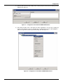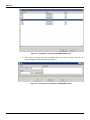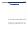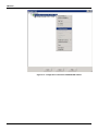
1
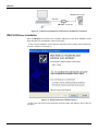
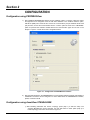
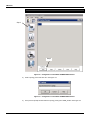
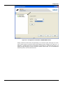
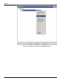
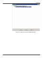
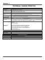
USER MANUAL
USB INTERFACE FOR
PROFIBUS PA
MAR / 12
PBI-PLUS
P B I P L U S ME
smar
www.smar.com
Specifications and information are subject to change without notice.
Up-to-date address information is available on our website.
web: www.smar.com/contactus.asp
INDEX
INDEX
SECTION 1 - INSTALATION .................................................................................................................... 1.1
GENERAL.............................................................................................................. 1.1
NETWORK WIRING .............................................................................................. 1.2
WIRING IN BENCH ............................................................................................... 1.3
PBI-PLUS DRIVER INSTALLATION ..................................................................... 1.4
SECTION 2 - CONFIGURATION .............................................................................................................. 2.1
CONFIGURATION USING ProfibusView............................................................... 2.1
CONFIGURATION USING AssetView STANDALONE ......................................... 2.1
SECTION 3 - TECHNICAL CHARACTERISTICS ..................................................................................... 3.1
III
User Manual
IV
Section 1
INSTALATION
General
PBI-PLUS is an advanced communication converter between PROFIBUS PA devices and USB
ports. It is intended to interface PROFIBUS PA devices such as transmitters, controllers, sensors,
actuators, converters, with devices such as PCs, notebooks, netbook or others, using their USB
ports.
PBI-PLUS enable PCs and notebooks to implement high level HMI supplanting dedicated PDA
(programmers). It allows device monitoring, parameterization and configuration. PROFIBUS PA
network management can be implemented by using any FDT frame application. Superior
performance and features can be achieved with PROFIBUSView and AssetView, the PROFIBUS
configurator and asset management system from Smar, respectively.
This interface was designed to be lightweight and rugged at the same time, thus facilitates its use.
PBI-PLUS dimensions can be seen in the Figure 1.1.
Figure 1.1 – Dimensional Drawing (mm)
1.1
PBI-PLUS
Network Wiring
The interface is connected to the computer through its USB cable and then, connected to the
PROFIBUS PA network through pinch connector. Refer to Figure 1.2. For this case, the side switch
must be in the NETWORK position.
NOTE
NETWORK option disables the power supplied by the interface, since the PROFIBUS channel is
expected to be running and properly powered by the main control system.
Figure 1.2 – PBI-PLUS Interface
1.2
Installation
Figure 1.3 – Wiring diagram showing the PBI interface and PA network connection (e.g
system using DF73 – PROFIBUS DP Controller)
IMPORTANT NOTE RELATED WITH DF95 AND DF97 CONTROLLERS FROM SMAR
Due the fact these controllers have both DP and PA channels embedded, and also due the fact they
already have the PBI-PLUS communication features, is NOT possible to connect this interface in
any of PA channels of these controllers.
Wiring in Bench
For this case, the side switch must be in LOCAL position.
NOTE
The local option enables not only the power through the interface, as well as the necessary
impedance control for communication with the PROFIBUS PA.
1.3
PBI-PLUS
PROFIBUS PA - Device
USB cable
PBI-PLUS – connection
Figure 1.4 – Interface wiring diagram for workstation to the PA device connection
PBI-PLUS Driver Installation
When the PBI-PLUS is connected to the computer's USB port, a screen driver installation screen
will be prompted. For this installation, follow the next steps:
- 1º step: in the first installation screen, select the “Install from a list or specific location (advanced)”
and click in “Advance”. See Figure 1.6.
Figure 1.5 – Step-by-step Driver Installation (Part 1)
- 2ª step: in the next screen the user shall point the driver’s folder. After finding it, click in “Next” as
in Figure 1.7.
1.4
Installation
Figure 1.6 – Step-by-step driver installation (Part 2)
- 3º step: after selecting the right directory, the driver will be installed and a conclusion message will
be displayed. See figure 1.8.
Figure 1.7 – Step-by-step driver installation (Part 3)
1.5
PBI-PLUS
After finishing this step and in order to proceed with installation, the initial installation message will
be prompted again. No directory will need to be chosen, once the right folder path will be displayed
in the prompted window.
The created virtual serial port will be same to be selected within the software application
(e.g.AssetView, ProfibusView) to allow the communication with PBI-PLUS.
1.6
Section 2
CONFIGURATION
Configuration using PROFIBUSView
1)
After initializing PROFIBUSView software, choose "Settings" option. In "Device" combo box, select
the equipment to be configured. Insert the real device address. In the “Profibus Interface” option,
“PBI-PLUS (USB)” item should be set. Choose the communication port (the installed virtual serial
port) and then, choose the communication scheme: “LOCAL” option for bench use or “NETWORK”
option for powered PA channels. Details about those communication types can be seen in the
Chapter 1. Figure 2.1 shows the screen’s configuration detail.
Figure 2.1 – Configuration of PROFIBUSView software
2)
After the initial setup done, the PROFIBUSView’s communication between hardware and software is
established. The device can be configured. For more details about the PROFIBUSView software,
please, consult its manual.
Configuration using AssetView STANDALONE
1) After initializing AssetView SA, choose “Topology” option (step 1) to start the setup. The
“Topology Management” will be prompted, the user shall select in “New” option (step 2) to
create a topology. This screen can be seen in Figure 2.2.
2.1
PBI-PLUS
NOTE
Refer to AssetView’s manual for software installation details.
Step 1
Step 2
Figure 2.2 – Configuration of AssetView STANDALONE software
2)
Insert a topology name and click “OK”. See Figure 2.3.
Figure 2.3 – Configuration of AssetView STANDALONE software
3)
2.2
In the previous prompt window shows the topology name given: SMAR_TESTE. See Figure 2.4.
Configuration
Figura 2.4 – Configuration of AssetView STANDALONE software
4)
Right click in the “My network” icon, choose “Add DTM” and insert the PBI CommDTM. It will work
as a communication gateway between AssetView and the device. Refer to figure 2.5 and figure 2.6
for detailed procedure.
2.3
PBI-PLUS
Figure 2.5 – Configuration of AssetView STANDALONE software
Figure 2.6 – Configuration of AssetView STANDALONE software
2.4
Configuration
5)
Selecting “PBI” option and then clicking “OK”, it will be prompt a screen where the PBI tag shall be
attributed. See Figure 2.7.
Figure 2.7 – Configuration of AssetView STANDALONE software
6)
After setting the PBI’s TAG, it will appear just below “MyNetwork”. The next step is adding the
device to be configured. To do so, just right click on PBI-PLUS and choose “Add DTM/Block…”
option. See Figure 2.8. Finalize de procedure clicking “OK”. See Figure 2.9.
Figure 2.8 – Configuration of AssetView STANDALONE software
2.5
PBI-PLUS
Figure 2.9 – Configuration of AssetView STANDALONE software
7)
Once created, the device shall have an attributed TAG. See Figure 2.10. Then, click “OK”. The
device will appear just below the PBI. See Figure 2.11.
Figure 2.10 – Configuration of AssetView STANDALONE software
2.6
Configuration
Figure 2.11 – Configuration of AssetView STANDALONE software
8)
Then, an offline parameterization in PBI shall be done. Right-click on PBI and choose “Offline
Parameterization” option. See Figure 2.12. Click on “Master Settings” option. It will be prompt a
interface to configured the communication port (“Serial Port” option) to be used. It also be prompt
the communication type (“Interface” option), that it should be set to local (“LOCAL” option) or to
network (“NETWORK” option) depending on the application. See Figure 2.13.
2.7
PBI-PLUS
Figure 2.12 – Configuration of AssetView STANDALONE software
2.8
Configuration
Figure 2.13 – Configuration of AssetView STANDALONE software
Finally, set device to online mode, just right-clicking on “Go to online” option. See Figure 2.14. Then,
check if both interface and device TAGs become bold and Italic formatted. See Figure 2.15. If
affirmative, it indicates that device and AssetView communication is operational and ready to be
started, just right-click again on device to select the desired online function. For more details about
AssetView, please, consult its official manual.
2.9
PBI-PLUS
Figure 2.14 – Configuration of AssetView STANDALONE software
2.10
Configuration
Figure 2.15 – Configuration of AssetView STANDALONE software
2.11
PBI-PLUS
2.12
Section 3
TECHNICAL CHARACTERISTICS
Functional Specifications
Power Supply
Open Voltage 15.15 Vdc
Communication Standard
Indicator
Certifications in
Hazardous Locations
Temperature Limit
Configuration
Minimum System
Requirement
Via USB 5 Vdc port
Compatívelible with USB 1.1 and USB 2.0
Voltage with 12 mA output 14.9 Vdc USB current 5 Vdc x 35 mA
Voltage with 36 mA 13,2 Vdc USB current 5 x 80 mA
Output current – 96 mA USB short current – 142 mA
IEC 1158-2, 31.25 kbits/s for Fieldbus. (Foundation Fieldbus and PROFIBUS PA).
ON – Led indicates the interface is connected to USB port.
COMM – Led indicates the interface started the communication with the device.
FAIL - Led light when the interface is in local mode and a short-circuit occurs in the device power terminals.
It is not certified to be used in potentially explosive atmospheres.
Operation:
0 a
50 °C @ 10 a 90 RH (noncondensing)
Storage:
-30 a
70 °C @ 5 a 90 RH (noncondensing)
PBI-PLUS is a device used to interface the communication between Profibus PA devices and configuration software.
The software used for configuration of the devices is ProfibusView or AssetView from Smar, or any software based
on FDT/DTM technology. Licenses necessary (Writing license for ProfibusView, or 4-Devices fully operational Demo
license for AssetView SA or/and free comm.DTM for any other FDT/DTM based software).
Processor de 1 GHz
2 GB RAM
5 GB of free disk space
Windows XP 32 bits SP3
A complementary list of approved operational systems is listed below:
Windows 7 64 bits Professional (running in 32 bits compatibility mode)
Windows 7 64 bits Ultimate (running in 32 bits compatibility mode)
Windows 7 64 bits Enterprise (running in 32 bits compatibility mode)
Windows Server2008 64 bits SP2 (running in 32bits compatibility mode )
Windows XP 32 bits SP3
Windows Server2003 32 bits SP2
Performance Specifications
Electromagnetic
Interference Effect
Compatible with IEC61326-1 EMI immunity standard.
Cable
Insulation
Material
Dimensions
With USB connection at the host system side and with retractable claws at the instrumentation side.
Galvanic insulation between Profibus and USB port.
Injected ABS plastic enclosure.
123 x 68 x 30 (mm)
Physical Specifications
3.1
PBI-PLUS
3.2