1
3.4 Precautions for Start-up and Maintenance
・Use the product within the ratings specified in this manual. If it is used outside the ratings, it may cause
not only malfunction or failure but also fire or burnout.
・Before operating the product, check that active bare wire, etc. does not exist around the product. If any
bare wire is found, stop the operation immediately, and take an appropriate action such as isolation
protection.
・Do not disassemble or modify the unit. It may cause failure, malfunction, injury or fire.
・Attaching and detaching the unit must be performed after the power source is shut off for all outside
phases. If all phases are not shut off, it may cause electric shock, failure or malfunction of the unit.
・Do not touch powered wires. It may cause malfunction.
・Tighten mounting screws and cleaning unit must be performed after the power source is shut off for all
outside phases. If all phases are not shut off, it may cause electric shock, failure or malfunction of the
Caution
unit.
・Use a soft dry cloth to clean off dirt of the unit surface.
・Do not let a chemical cloth remain on the surface for an extended period of time nor wipe the surface
with thinner or benzene.
・Check for the following items to use this unit properly for long time.
<Daily maintenance>
(1) No damage on this unit (2) No abnormality with LED indicators (3) No abnormal noise, smell or
heat.
<Periodical maintenance (Once every 6 months to 1 year) >
(4) No looseness with installation, wire connection to terminal blocks, and connector connection.
(Check these items under the electric outage condition.)
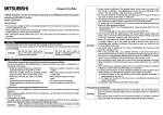
4.2 Names and functions of LEDs
The following describes names and functions of LEDs.
Name
Color
Role
RUN LED
Green
Displays the operation status of this unit.
ERR. LED
Red
Displays errors and conditions of this
unit.
ALM1 LED
Red
Displays alarm 1 occurrence status.
ALM2 LED
Red
Displays alarm 2 occurrence status.
MEA. LED
Green
1 LED
Green
2 LED
Green
3 LED
Green
Displays the status of measurement of
this unit.
Displays the status of measurement
(regeneration)at side 1 of this unit.
Displays the status of measurement
(regeneration) at side 2 of this unit.
Displays the status of measurement
(regeneration) at side 3 of this unit.
Indicator condition
Normal operation
5V power discontinuity, watch dog timer error
Error occurring (except out-of-range error) *1
*1
Out-of-range error
Normal operation
Alarm 1 occurring
Alarm 1 occurring → Not occurring
(In the case of alarm 1 reset method =
self-retention)
OFF:
Alarm 1 not occurring
Flashing: Alarm 2 occurring
ON:
Alarm 2 occurring → Not occurring
(In the case of alarm 2 reset method =
self-retention)
OFF:
Alarm 2 not occurring
Flashing: Measurement existing(consumption)
ON:
Measurement existing(regeneration)
OFF:
Measurement not existing (no measurement)
ON:
Measurement at side 1 existing (regeneration)
OFF:
Other than the above
ON:
Measurement at side 2 existing (regeneration)
OFF:
Other than the above
ON:
Measurement at side 3 existing (regeneration)
OFF:
Other than the above
ON:
OFF:
ON:
Flashing:
OFF:
Flashing:
ON:
1 For details, check with the list of error codes. (Refer to section 9.1)
※ :
3.5 Disposal Precautions
・When disposing of this unit, treat it as industrial waste.
5. Attaching and removing the unit
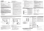
5.1 How to attach to the base unit
4. Name and function of each part
Insert it securely so that t he
protruding portion for fixing t he
1
unit * does not come off of t he
unit -f ixing hole.
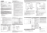
4.1 Names and functions of parts of QE81WH are provided below.
(1)LED
Operation status of this
unit is displayed. (Refer
to 7-4.)
(5) Push button
Use this button to
insert a cable to the
terminal or to remove
them.
(6) Check hole
Use this for continuity
check to the terminal.
Use it with a tester
contact.
(7) Strip gauge
A gauge that is used for
checking the length of
stripped wire which is
connecting to voltage
input terminals.
(2) Strip gauge
A gauge that is used for
checking the length of
stripped wire which is
connecting to current input
terminals.
(3) Current input terminals
Connect the secondary
output of the dedicated
current sensor which has
been connected to the
measuring circuit.
(4) Voltage input terminals
Connect the output wire of
the Voltage transform unit.
Names of signals of terminal block
Terminal
symbol
1k
1l
2k
2l
3k
3l
PA
PB
PC
PD
SLD
Base unit
Name of terminal
1-phase current input
terminal (power source side)
1-phase current input
terminal (load side)
2-phase current input
terminal (power source side)
2-phase current input
terminal (load side)
3-phase current input
terminal (power source side)
3-phase current input
terminal (load side)
Voltage input terminals
(Connect the output wire of the
voltage transform unit)
Push the unit t oward the arrow
direct ion, as the unit-fixing hole
being a fulcrum point, unt il you
hear a c lick s ound to firmly
attach it to the based unit.
Supplementary ---------------------------------------------------------------------------------------------------------------------------------------------Check the stripping length using the strip gauge of QE81WH main unit.
Unit c onnector
Base unit
Protrusion for fixing
the unit (*1)
Chec k that the unit is firm ly
ins erted t o the bas e unit.
Unit
Lever for att aching
the unit
H ole f or fixing the unit
Complet e
Attach to the base unit of MELSEC-Q series.
When attaching the unit, make sure to insert the protruding portions for fixing the unit into the holes on the base unit. In
doing so, insert it securely so that the protruding portion of the unit does not come off of the holes. Do not force to attach
the unit; otherwise the unit may break.
・When installing the unit at a vibrating area with strong impact, tighten the unit to the base unit using screws.
Fixing-Unit screw (arranged by user): M3 x 12mm
Tightening torque of the fixing-unit screws: 0.36 – 0.48 N•m
・
shield terminal
Hook for fixing the
unit (*2)
・