1
Contents
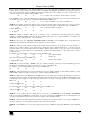
Figures
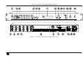
Figure 1: VS-5x5 5x5 Video Audio Matrix Switcher
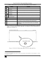
Figure 2: VS-5x5 5x5 Video Audio Matrix Switcher Underside View
Figure 3: Connecting the VS-5x5 5x5 Video Audio Matrix Switcher
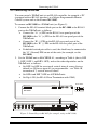
Figure 4: Connecting a PC without using a Null-modem Adapter
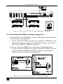
Figure 5: Controlling via RS-485 (for example, using an RC-3000)
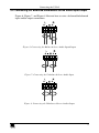
Figure 6: Connecting the Balanced Stereo Audio Input/Output
Figure 7: Connecting the Unbalanced Stereo Audio Input
Figure 8: Connecting the Unbalanced Stereo Audio Output
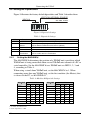
Figure 9: Dipswitch Settings
Figure 10: Cascading Individual Units in a Control Configuration via RS-232 and RS-485
Figure 11: VS-5x5 Unit Characteristics
Figure 12: Storing and Recalling using the Input / Output Buttons
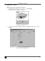
Figure 13: Splash Screen
Figure 14: Atmel – Flip Window
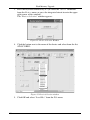
Figure 15: Device Selection Window
Figure 16: Device Selection window
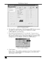
Figure 17: Loading the Hex
Figure 18: RS-232 Window
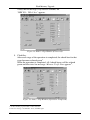
Figure 19: Atmel – Flip Window (Connected)
Figure 20: Atmel – Flip Window (Operation Completed)
3
5
7
7
8
9
9
9
10
12
13
16
19
19
20
20
21
21
22
22
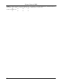
Tables
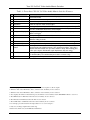
Table 1: Front Panel VS-5x5 5x5 Video Audio Matrix Switcher Features
Table 2: Rear Panel VS-5x5 5x5 Video Audio Matrix Switcher Features
Table 3: Dipswitch Settings
Table 4: Machine # Dipswitch Settings
Table 5: Technical Specifications of the VS-5x5 5x5 Video Audio Matrix Switcher
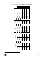
Table 6: VS-5 5 Hex Codes for Switching via RS-232/RS-485
Table 7: VS-5 5 Hex Codes for Audio Input Gain Control
Table 8: VS-5 5 Hex Codes for Audio Output Gain Control
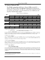
Table 9: Protocol Definitions
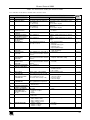
Table 10: Instruction Codes for Protocol 2000
ii
4
5
10
10
23
24
25
27
28
29
KRAMER: SIMPLE CREATIVE TECHNOLOGY