1
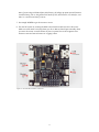
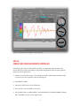
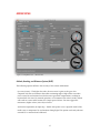
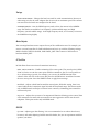
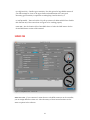
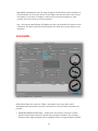
!
!
B32 GIMBAL CONTROLLER
USER GUIDE
!
!
!
!
!
!
!
BeeWorks LLC
www.beeworksgear.com
Last Modified: April 2014
Based on the “SimpleBGC Software User Manual” by BaseCam Electronics
Copyright © 2014 BeeWorks LLC. All rights reserved.
!
!
CHAPTER 1
!
OVERVIEW
This manual covers the setup, calibration, and operating modes of the BeeWorks B32
Gimbal Controller + IMU. It also covers the “SimpleBGC GUI” software application
produced by BaseCam Electronics.
The basic principle of the B32 Gimbal Controller is to input data from a stand-alone inertial
measurement unit (IMU) to control three brushless motors, each of which is responsible
for stabilizing an axis. The IMU contains electronic accelerometers and gyroscopes to sense
roll, pitch (tilt), and yaw (pan). If using the B32 Gimbal Controller to stabilize a camera,
the IMU must be mounted in the same location as the camera to sense camera movement.
PEDIGREE
The B32 Gimbal Controller is a circuit board manufactured in the USA by BeeWorks under
license to BaseCam Electronics. The BeeWorks B32 Gimbal Controller is manufactured in a
facility designed for the production of aerospace electronics and meets all standards set
forth in the Restriction of Hazardous Substances (RoHS) Directive.
The reference design from BaseCam Electronics is named “SimpleBGC” (Brushless Gimbal
Controller). Different manufacturers, such as BeeWorks, have licensed and adapted this
design into their own products. This manual covers the BeeWorks version of the 32-bit
SimpleBGC. Since the design is based on a standard architecture, most of the material in
this manual applies to other versions of the board, as well.
BaseCam Electronics also develops a multi-platform software application called SimpleBGC
GUI (Graphical User Interface), which is used to configure their gimbal controller family.
This manual includes material from BaseCam’s “SimpleBGC Software User Manual” that
BeeWorks has edited and adapted for this guide.
!2
!
!
!
CHAPTER 2
GETTING STARTED
We recommend that you test your B32 Gimbal Controller, motors, and IMU before
installing them in your application. For this test, you will need to accomplish the following
steps, all of which are described in greater detail later in the manual but outlined here
1. Download and install the SimpleBGC GUI software application from BaseCam
Electronics: www.basecamelectronics.com/downloads/32bit/
2. Connect the B32 Gimbal Controller to your computer with a mini USB cable. If your
computer does not detect the controller automatically, you can download the latest
drivers from the following link: www.silabs.com/products/mcu/pages/
usbtouartbridgevcpdrivers.aspx
3. Connect the IMU and motors to the B32 Gimbal Controller. Reference Figure 2.1 below
for proper connections.
4. Auto-detect the number of poles for your motors or enter the number manually. For
more information, refer to the NUM.POLES description.
5. Set parameters P=0, I=0.1, D=0 for each axis. For more information, refer to the PID
description.
6. Connect your battery to the B32 Gimbal Controller. The B32 Gimbal Controller comes
with a power cable that has bare wire leads. Solder a connector to the wires that mates
with the connector on your battery. Pay careful attention to the positive and negative
terminals on your battery and ensure that you never short them or connect the battery
backwards. Doing so will damage the B32 Gimbal Controller and may cause your battery
to explode. Make sure that your battery is between 8 and 25V.
"3
Note: If you are using a Lithium Polymer (LiPo) battery, this voltage spec means you need between a
3S and 6S battery. The “S” designation is the number of cells, and each cell is 3.7V. Therefore, a 3S
LiPo is 11.1V, while a 6S battery is 22.2V.
7. Set enough POWER to get the motors to move.
8. Test the full system by rotating the IMU sensor board around each of its three axes.
Make sure each motor is moving when you do so. Motors should spin smoothly when
you move the sensor. A small amount of jitter is normal, due to the magnetic force
between rotors and stators known as “cogging” effect.
Figure 2.1 B32 Gimbal Controller Connectors
"4
!
!
CHAPTER 3
STEP-BY-STEP SETUP
The following section outlines the steps required to set up and tune a gimbal using the B32
Gimbal Controller. Refer to later sections of this manual for greater details about the
software settings. This section is intended to provide a “big picture” view of the overall
process, so that you understand the purpose of more detailed sections in the manual. The
steps below assume you have completed a basic setup test, as specified in Chapter 2:
Getting Started.
STEP #1:
CONNECT THE B32 GIMBAL CONTROLLER TO YOUR COMPUTER
Connect the board to your computer with a mini USB cable. The first time you connect the
board to your computer, it may install the drivers automatically. If not, you can download
the latest drivers from the following link: www.silabs.com/products/mcu/pages/
usbtouartbridgevcpdrivers.aspx
After you install the driver, a new virtual COM port will be created. You need to choose this
COM port in the SimpleBGC GUI software application to initiate the connection.
Caution: It is safe to connect both USB and the battery simultaneously, but be very careful not to reverse
the polarity of the battery, because it will burn out the controller and may damage your PC!
!
"5
!
STEP #2:
UPDATE THE FIRMWARE
Your BeeWorks B32 Gimbal Controller comes preloaded with the latest firmware at the
time it is shipped. You can verify that you have the latest firmware by connecting the board
to a computer with a mini USB cable. This connection also will enable you to adjust
settings on the board itself.
STEP #3:
ADJUST GIMBAL MECHANICS
Mount the camera on the camera tray and balance the gimbal in all three axes. Stabilization
quality depends on balance quality. To check the balance, ensure the gimbal is turned off,
hold the gimbal in your hands and make fast motions along all three axes. If the camera
remains still, then the gimbal is balanced correctly. Proper balance and low friction will
reduce power consumption and improve stabilization quality.
If you rewound the motors yourself, we recommend checking the winding. Remove the
motors from the gimbal, connect them to the controller and set parameters P=0, I=0.1,
D=0 for each axis. Set enough POWER to get the motor to move, and connect your battery.
Motors should spin smoothly when you move the sensor. A small amount of jitter is normal
due to the magnetic force between rotors and stators (“cogging” effect).
Pay great attention to the IMU sensor installation. The IMU axes must be parallel to the
motor axes, and the IMU must be configured properly (i.e. mounting orientation set). Pay
close attention to mechanical linkages. They must be extremely rigid and backlash-free. The
IMU sensor provides feedback data for stabilization, and small amounts of freedom or
flexibility will cause feedback delays and low-frequency resonances. In such cases, it will be
more challenging to find acceptable PID settings and ultimately will result in unstable
performance in real-world conditions (multi-rotor frame vibrations, wind, etc).
STEP #4:
CALIBRATE THE SENSOR
CALIBRATING THE GYROS
Each time you turn the controller on, it takes about 7 seconds to power-up and calibrate the
gyro. Try to immobilize the sensor (camera platform) as much as possible in the first few
seconds after power-up, while the green LED is blinking.
"6
If you activated the option to “Skip gyro calibration at startup,” the gyro is not calibrated
every time, and the controller will start working immediately after power-up. Recalibrate
the gyro manually if you notice degradation in the stabilization quality.
CALIBRATING THE ACCELEROMETERS
It is necessary to calibrate the IMU prior to installation, and it is recommended to recalibrate it occasionally, particularly when the temperature changes significantly.
Simple calibration mode – Set the IMU sensor flat on the table and press CALIB.ACC in the
software (or the menu button on the controller, if it is assigned). The LED will blink for 3
seconds. Do not move the sensor during calibration. The sensor does not need to be
connected to the camera platform for this step, as you are calibrating the sensor, not the
camera.
Advanced calibration mode – Perform calibration in simple mode first, as described above.
Then, rotate the sensor board so that each side of the sensor faces up (6 positions total).
Fix the sensor in each position, press the CALIB.ACC button in the software and wait about
3-4 seconds while the LED is flashing. The order of the other sides does not matter, as long
as the base position used in the Simple calibration mode is first. You do not need to press
the WRITE button —calibration data is written automatically after each step.
NOTE: Precise accelerometer calibration is extremely important for holding the horizon during dynamic
movements or yaw rotation.
STEP #5:
TUNE BASIC SETTINGS
Prior to tuning the gimbal, ensure that the IMU is configured and calibrated and that Follow
Mode is not enabled (ensure “Estimate frame angles from motors” is off and Follow YAW is
off). “+” should be set to zero. PWM frequency should be set correctly for your application
prior to tuning.
1. Connect the battery.
2. Set POWER such that the motors have enough torque to hold the camera in place but
do not overheat. Wait at least five minutes to ensure the motors do not get too hot at
that setting. Find the lowest power setting that still provides adequate holding torque,
even when the camera is disturbed.
3. Set PID values for all axes to zero.
"7
4. Auto-detect the number of poles and the motors’ direction. If you know the number of
poles for your motors, it is best to enter the value manually. Do not proceed to the next
step until proper direction is detected.
5. It is best to configure the PID settings for each axis individually, starting with PITCH. To
check stabilization quality, use the peak indicator (shown by the blue traces and blue
numbers) in the control panel on the right of the software. Incline the frame by small
angles, and try to minimize the peak values by increasing P, I and D according to the
following algorithm:
i.
Set “I” to a small value of 0.05 or less.
ii.
Slowly increase “P” until the motor starts to oscillate.
iii. Increase “D” in small increments until the oscillations stop.
iv. Repeat steps ii and iii until high-frequency vibration occurs. You may feel the
vibration by hand and see a noisy line on the gyro graph. At this point, you have
identified the maximum values for “P” and “D” for PITCH for your setup. Decrease
each slightly and proceed to step v.
v.
Repeat steps i through iv for ROLL. Stabilization of ROLL may cause instability in
PITCH. If so, reduce P and D slightly for PITCH. Cross-axis interference is most
pronounced when the gimbal construction is less rigid.
vi. Repeat steps i through v for YAW.
vii. Increase “I” for PITCH until low-frequency oscillation appears. Then, decrease “I”
slightly to keep the gimbal stable. You can reduce “I” as much as 20%, if needed.
viii. Repeat step vii for ROLL and YAW.
ix. When all axes are tuned, test the gimbal. You may find it helpful to use the gyro
data from the Realtime Data tab to estimate stabilization quality. Turn off all data
except GYRO and gently tap the camera in the direction of the axis you are
configuring. This impulse will display on the graph as a fading wave as shown in
Figure 3.1 below. The oscillation should damp within two to four cycles. If the
oscillation continues beyond that point, further adjustment of the rig is required.
Reduce the gain factors (P, I) or increase the damping factor D to reduce these
oscillations.
The result of good tuning is that stabilization error will be less than one degree when you
gently rock the gimbal’s frame.
"8
Figure 3.1 Turning PID in the SimpleBGC software application
STEP #6:
CONNECT AND CONFIGURE REMOTE CONTROL (RC)
Connecting a RC system to the gimbal is optional. A configuration that includes a RC
system will allow control and aiming of the gimbal independently from the direct physical
movements of the gimbal unit.
1. Connect one of the RC receiver’s free channels to the RC_PITCH input, making certain
to preserve the correct polarity in the RC Settings tab.
2. Set SOURCE=PWM.
3. Assign RC_PITCH input to the PITCH axis.
4. Leave all other axes and CMD as “no input.”
5. For the PITCH axis, set MIN.ANGLE=-90, MAX.ANGLE=90, ANGLE MODE=checked,
LPF=5, SPEED=10 (not used in angle mode).
"9
6. Connect the battery to the main controller and receiver, and check that RC_PITCH input
receives data in the “Realtime Data” tab (slider should be filled blue and reflect stick
movement).
Now you can control camera PITCH from your RC transmitter from -90 to 90 degrees.
If you are not satisfied with the speed of movement, adjust the “I” setting for PITCH in
the “Basic” tab.
Experiment with SPEED mode to determine if SPEED or ANGLE mode is best for your
application.
7. Connect and tune the ROLL and YAW axes the same way, as required.
STEP #7:
TEST THE GIMBAL IN REAL-WORLD CONDITIONS
If your gimbal is attached to a multi-rotor aircraft, connect the controller to the SimpleBGC
GUI software application and turn on the multi-rotor motors. Check the vibrations on the
camera by using the Realtime Data tab / ACC raw data. Try to decrease the level of
vibrations using soft dampers.
NOTE: Brushless motors provide faster reaction than traditional servos but less torque. Depending on
your installation, it may be difficult for the motors to fight against wind and prop-wash. If you are
developing the multi-rotor aircraft frame yourself, try to avoid this influence by lengthening the motor
arms, tilting the motors away from center, or placing the camera above the props. Also, keep in mind that
deflected airflow, when moving at high speeds, can affect the gimbal.
"10
!
!
!
CHAPTER 4
“SimpleBGC GUI” SOFTWARE
OVERVIEW
The SimpleBGC GUI software application enables you to do the following:
•
Update the firmware on your controller
•
Define settings for your specific installation of the controller
•
Tune settings to get the optimal performance for your installation
•
Adjust settings for various modes of operation
USING SimpleBGC GUI
After you start the software and select the correct COM port from the list, click “Connect."
When the connection is established, all board settings and profiles will be loaded into the
software. You can re-load the current board parameters anytime by clicking the “READ”
button.
After adjusting parameters in the software, you should write them to the controller board
by clicking the “WRITE” button. Only the current profile parameters will be saved to the
board. To return to the default settings, select the “USE DEFAULTS” button.
To choose a different profile, select it from the list of profiles located in the upper right
corner of the window. You can store different settings as five different profiles onto the
controller board. You can switch profiles saved on the board by choosing the profile in the
software or by pressing the MENU button, if configured on your controller board.
"11
Remember that some settings are common for all profiles and can not be saved on a perprofile basis. Parameters such as sensor orientation, hardware configuration, RC inputs, and
motor outs are the same across all profiles.
The software starts in English. To change the interface language, choose one in the
“language” menu and restart the program.
SimpleBGC GUI LAYOUT
SimpleBGC GUI contains seven main sections, as illustrated below in Figure 4.1.
Figure 4.1 SimpleBGC GUI Layout
1. Connection – COM-port selection and connection status.
2. Profile – Select, rename, load, and save different profiles.
3. Configuration – Central part of the window, organized into seven tabs:
"12
i.
Basic – Basic gimbal stabilization settings. Adjusting these settings is usually
adequate to achieve good camera stabilization.
ii.
Advanced – More precise tuning options.
iii. RC Settings – Settings to control the gimbal roll/pitch/yaw orientation with RC
inputs.
iv. Service – Specify the behavior of the MENU button (located on the controller board
or mounted externally) and tune the battery monitoring service.
v.
Follow Mode – Settings related to this special mode of camera control.
vi. Realtime Data – Realtime sensor data monitoring. This screen is helpful in tuning
your gimbal performance.
vii. Firmware Upgrade – Firmware and SimpleBGC GUI software versions and update
options.
4. Control Panel – Graphic visualization of gimbal orientation angles for all three axes.
•
Black arrows display the angles.
•
Blue arrows are a 10x time magnification to provide higher precision.
•
Red marks show target angles that the gimbal should hold.
•
Thin blue lines show the peak deflection from the central, neutral point.
•
Blue digits show peak deflection amplitude, which provides an estimation of
stabilization quality.
•
Vertical red bars to the right of the scales show actual power level from 0 to 100%.
5. READ, WRITE, USE DEFAULTS buttons are used to transfer settings to/from the
controller board.
6. MOTORS ON/OFF button – Toggle motor state.
7. Tips, status or error messages (in red color) are displayed at the bottom of the screen.
Overall cycle time and I²C error count is also displayed.
8. Battery voltage indicator with warning sector.
"13
!
!
!
CHAPTER 5
“SimpleBGC GUI” REFERENCE
BASIC SETTINGS
Before tuning your controller, install the camera into the gimbal firmly, and ensure the
gimbal is balanced. Refer to your gimbal manufacturer’s balancing procedures for the best
way to balance your gimbal. In general, you want to ensure that your camera is positioned
such that each axis of the gimbal is balanced as precisely as possible.
Figure 5.1 SimpleBGC GUI – Basic Settings
"14
PID (PROPORTIONAL-INTEGRAL-DERIVATIVE)
The primary tuning parameters are PID. For a technical explanation of PID parameters in
control loops, refer to the following Wikipedia article: en.wikipedia.org/wiki/PID_controller
“P” – Defines the strength of response to a disturbance. Higher values mean a stronger
response to external disturbance. Raise this value until the stabilization quality is
adequate. However, if the “P” value is too high, oscillations of the axis will occur. These
oscillations will get worse if there are vibrations that reach the IMU sensor board. If
oscillations occur, raise the “D” parameter by one or two units, then try to raise the “P”
value again.
“I” – The “I” value changes the speed at which the gimbal moves to incoming RC
commands and moves back to neutral. Low values result in a slow and smooth reaction to
RC commands and returning to neutral position. Increase this value to speed up the
movement.
“D” – The “D” value reduces the reaction speed of the gimbal. This value helps to remove
low-frequency oscillations. A “D” value that is too high can cause high-frequency
oscillations, particularly when the IMU sensor is exposed to vibrations.
Limit Accelerations – Check this option to limit angular accelerations with RC or serial
control. Setting this limit prevents rapid movement and results in smoother camera control.
If your gimbal is mounted on a multi-rotor frame, setting this limit will result in less impact
to the frame in flight from quick movements of the camera. The lower the limit, the
smoother the camera movement but the longer it takes for the camera to move to the
desired point.
Power – The power setting defines the maximum voltage supplied to the motors (0-255,
where 255 means full battery voltage). Choose this parameter according to your motor
characteristics. Find the lowest power setting that still provides good stabilization and
adequate holding torque. A Power value that is too low will not provide enough force for
the motor to stabilize the camera, particularly in windy conditions, when the gimbal is not
well balanced, or if the gimbal suffers from mechanical friction. Slowly lower the Power
parameter to find its optimal value.
Caution: Avoid high power settings that cause your motors to get too hot. Motor temperatures over 80 °C
(176 °F) will cause permanent damage to motor magnets.
Raising the power is equivalent to raising the “P” value in the PID settings. If you raise the
POWER value, you should re-tune your PID values as well.
“+” – Additional power that will be added to the main power in case of a large error caused
by missed steps. This additional power helps to return the camera to the normal position. If
main power plus additional power (+) is greater than 255, the result is limited to 255.
"15
INVERT – Reverse motor rotation direction. It’s extremely important to choose the correct
motor rotation direction to not damage your gimbal. To determine the correct direction, set
the P, I, and D values to 0 and the POWER values to 80 (or higher if your motors don’t
produce enough force to hold/move the camera). Level the camera tray horizontally and
click the AUTO button in the “Motor configuration” settings. The gimbal will make small
movements to determine correct motor rotation direction. Wait for the calibration
procedure to complete. Then, re-set your PID values and tune your Power values.
NUM.POLES – Number of motor poles. This value needs to be equal to the number of
magnets in your motor’s bell. During the “auto” calibration process described above, this
value is automatically detected. However, sometimes the auto calibration process is unable
to determine the correct number. Most brushless gimbal motors are built with 14 poles
(magnets) and utilize a DLRK winding scheme. Count your motor magnets and enter this
value if the “auto” value is not correct.
SENSOR – Configure your IMU by specifying the IMU sensor board’s orientation and
position on the gimbal. For a standard IMU sensor installation, look at the gimbal from
behind, like the camera view out from the gimbal. From this perspective, the up and right
direction will match the Z and X axis, respectively. You can place the IMU sensor in any
direction, as long as its sides are parallel to each motor axis. Take extra care in this step. It
is important to align the sensor precisely and mount it firmly. The correct configuration of
the IMU should result in the following:
1. Camera pitches forward – the PITCH arrow spins clockwise in the software.
2. Camera rolls right – ROLL arrow spins clockwise in the software.
3. Camera yaws clockwise – YAW arrow spins clockwise in the software.
SKIP GYRO CALIBRATION AT STARTUP – With this option, the board starts working
immediately after powering on, using the saved calibration data from the last gyroscope
calibration. Stored calibration data may become inaccurate over time or during temperature
changes, however. We recommend that you recalibrate your IMU on a regular basis to
ensure the best performance.
"16
ADVANCED TAB
Figure 5.2 SimpleBGC GUI – Advanced Tab
Attitude, Heading, and Reference System (AHRS)
The following options influence the accuracy of the camera stabilization.
Gyro trust (0-255) – The higher the value, the more trust is given to the gyro data
compared with the accelerometer data when estimating angles. High values can reduce
errors caused by accelerations but also decreases gyro drift compensation, resulting in
horizon drift over time. For smooth operation, we recommend low values (40-80), which
will result in a more stable horizon for a longer period of time. For more aggressive
movements, higher values (100-150) are better.
Acceleration compensation (FC input only) – Enable this option to use a physical model of the
multi-rotor to compensate for accelerations during flight. This option works only when an
external FC is connected and calibrated.
"17
Timings
SERIAL PORT SPEED – Changes the baud rate used for serial communication. Decrease it
when using over-the-air serial adapters that do not work at maximum speed. The software
can auto-detect the baud rate configured in the board.
PWM FREQUENCY – Sets the PWM frequency used to drive the motors in the POWER
stage. Two modes are available: Low Frequency (within audible range) and High
Frequency (outside audible range). In the high-frequency mode, it is necessary to increase
the POWER setting slightly.
Motor Outputs
You can assign hardware motor outputs for any of the stabilization axes. For example, you
can use a second controller for YAW stabilization and set it up with the following settings:
ROLL=disabled, PITCH=disabled, YAW=ROLL_OUT. Then connect a YAW motor to
hardware ROLL_OUT.
RC Sub-Trim
RC Sub-Trim allows correction of transmitter inaccuracy.
ROLL, PITCH, YAW trim – Enables trimming of the center point. The central point is PWM
1500. It is better to trim the center point with the transmitter, but if it is not possible to
do so (when using a joystick, for example), you can use the AUTO function in the
software. Place the stick in the center and press the AUTO button. Actual data becomes
the new center point. Press the WRITE button to apply these settings.
Dead band – Adjusts a dead band around the neutral point. With this setting, there is no
control while the RC transmitter signal is inside the dead band range. This feature works
only in SPEED mode and helps to achieve better control by eliminating jitter around the
stick neutral point.
Expo curve – Adjusts the curvature of an exponential function allowing precise control from
a RC transmitter for small stick movements but more aggressive control near the stick
endpoints. This option works only in SPEED mode.
SENSOR
Gyro LPF – Adjusts gyro data filtering. It is not recommended to set values other than 0,
because it will make adjusting the PID controller harder, but you can experiment with this
option if you desire.
"18
Gyro high sensitivity – Doubles gyro sensitivity. Use this option for large DSLR cameras if
your PID settings are close to the upper limits and stabilization still is not good.
Increasing gyro sensitivity is equivalent to multiplying P and D values by 2.
I²C Pull-ups Enable – Turns on built-in I²C pull-up resistors for SDA and SCL lines. Enable
this function only if the sensor does not appear to be working properly.
Frame IMU – Set the location of the frame IMU above or below the YAW motor. See the
Second IMU Sensor section of this manual.
SERVICE TAB
Figure 5.3 SimpleBGC GUI – Service Tab
MENU BUTTON – If you connected a menu button to the BTN connector on the controller,
you can assign different actions to it. Note that many of these button functions are the
same as options in the software.
!
"19
Available actions include:
i.
Use profile (1, 2, 3, 4 or 5) – Loads selected profile
ii.
Calibrate ACC – Accelerometer calibration
iii. Calibrate Gyro – Gyroscope calibration
iv. Swap RC PITCH-ROLL – Temporarily swap RC inputs from PITCH to ROLL. In most
cases only one PITCH channel is enough to control a camera on 2-axis systems. Before
a flight, you can swap control from the pitch channel to the roll channel to keep the
camera level in flight. Activating this function again swaps channels back and saves the
roll position in static memory.
v.
Swap RC YAW-ROLL – Similar to the Swap RC PITCH-ROLL options, this option
switches RC inputs from YAW to ROLL.
vi. Set tilt angles by hand – Selecting this option will turn off the motors for a few seconds
and enable you to fix the camera position by hand. After a few seconds, the Controller
will save and hold the new position. This function may be useful to correct camera
position before flight if there is no RC control connected.
vii. Reset controller
viii. Motors toggle, Motors ON, Motors OFF – Turn motors on or off.
ix. Inverse Yaw Motor – Reverse YAW motor direction.
BATTERY MONITORING – The 32-bit board has a voltage sensor installed to monitor the
main battery voltage to avoid damaging the battery. Battery monitoring is used to apply
voltage drop compensation so that PID remains stable throughout the battery lifecycle. The
battery monitor also triggers low-voltage alarms and cuts off power to the motors when the
battery becomes discharged.
i.
Calibrate – Adjusts the rate of the internal multiplier to make the measured voltage
more precise. Use a multimeter to measure the actual voltage, than enter this value in
the calibration dialog.
ii.
Low voltage - alarm – Set the voltage threshold at which the alarm will sound.
iii. Low voltage - stop motors – Set the voltage threshold at which the controller stops the
motors, to avoid damaging the battery.
iv. Compensate voltage drop – Set this option to increase POWER automatically as the battery
loses voltage.
"20
v.
Set defaults – Select the battery type to autofill the fields with default settings for your
battery.
BUZZER – Some boards include an output to a buzzer, which is used to alert on certain
events. These events are enabled or disabled in the software. Connect an active buzzer with
an internal sound generator that operates between 5 and 12V and currents below 40mA.
REALTIME DATA
The Realtime Data tab displays the raw sensor data stream and logical RC input levels.
Figure 5.4 SimpleBGC GUI – Realtime Data
ACC_X,Y,Z – Accelerometer data.
GYRO_X,Y,Z – Gyroscope data. This data helps to determine the quality of the P and D
settings. Disturb the gimbal by hand to see the data trace. If the data looks like a sine
wave, the D setting is too low, and the gimbal will be susceptible to low-frequency
oscillations. If some level of noise is present without any disturbance, the D setting is too
high, and the gimbal is susceptible to high-frequency self-excitation.
"21
ERR_ROLL,PITCH,YAW – Stabilization error graph. This data is the same as the peak
indicators on the control panel and shows maximum deflection angle.
Each graph can be turned on or off, and scale can be adjusted for the Y axis. You can pause
the data transmission at any time.
"22
!
!
CHAPTER 6
!
OPTIONAL GIMBAL FEATURES
BLUETOOTH
The BeeWorks B32 Gimbal Controller supports the option to connect a Bluetooth–To-Serial
adapter (HC-05, HC-06, SparkFun BlueSMiRF, and comparable) to connect to the
SimpleBGC GUI software application and tune the board remotely. There is a special
connector on the board that matches the connector on the Bluetooth module. It is marked
as SERIAL and contains pins: +5V, GND, RX, TX. You can solder the Bluetooth module
over it or use a Male-Male 4-pin cable extender.
IMPORTANT NOTE: The Bluetooth module must be configured at 115,200 baud rate and Even parity.
Generally, this baud rate is not set by default. Refer to your module’s user manual to find out how to
configure Bluetooth. With these settings, you will be able to modify software settings and even upgrade
firmware remotely.
SECOND IMU SENSOR
There is an option to install a second IMU sensor on the gimbal’s frame. The advantage of a
second IMU is more precise stabilization. You may use lower PID’s to get the same quality
when the B32 Gimbal Controller is aware of frame orientation. This option greatly improves
3-axis stabilization and extends the range of angles at which the gimbal remains
operational.
The second IMU should be connected to the same I²C bus as the main IMU (in parallel).
Note that the two IMU sensors must have different I²C addresses. The main IMU is 0x68,
while the frame IMU is 0x69. On the BeeWorks IMU, address 0x69 may be set by cutting
the ADDR bridge located on the back side of the sensor or by purchasing a frame IMU that
already has this bridge disabled.
"23
MOUNTING THE FRAME IMU
There are two options for placement of the second IMU: below the YAW motor and above
it.
If the sensor is placed above the YAW motor, it helps to stabilize ROLL, PITCH and YAW.
The system in this configuration becomes less stable during long work, however, because
the frame heading, estimated from the second IMU, may drift with time, and autocorrection may not work in all cases. If the sensor is placed below the YAW motor, it does
not help YAW axis stabilization but works more reliably.
Like the main (camera) IMU, the frame IMU may be mounted in any orientation, keeping
its axis parallel with the motor axes.
CONFIGURING THE FRAME IMU
To configure the frame IMU, first set its location in the “Advanced” tab, “Sensor” area.
Write settings to the board and go to the “Basic” tab. Select the “Frame IMU” button. If the
frame IMU is connected properly, this button becomes active and it means that all IMU
settings in the software now affect the frame IMU. Change sensor orientation (axis TOP,
RIGHT) and write the settings to the board, if necessary. After the board restarts, calibrate
the accelerometer and gyroscope like you did for the main IMU. For the accelerometer, you
can choose simple calibration or extended 6-point calibration.
You will notice that the right Control panels are now displaying angles for the frame IMU
and not the main IMU. Also, in the “Realtime Data” tab, the accelerometer and gyroscope
data is now for the frame IMU. Ensure the orientation of the frame IMU sensor is properly
configured, and check its calibration in the same manner you did for the main IMU.
RADIO CONTROL (RC)
Connecting a Remote Control system to the gimbal is optional. A configuration that
includes a RC system will allow control and aiming of the gimbal separately from the direct
physical movements of the gimbal unit.
RC INPUT MAPPING – In this section you can assign hardware RC inputs to virtual control
channels. There are four hardware inputs provided on the board for RC connections,
which you can assign to control any of three channels, one for each axis, and one
command channel. If control for an axis is not needed, leave the option as “no input”.
!
"24
RC_ROLL PIN MODE – Allows configuration of several formats of incoming signal for the
RC_ROLL pin:
i.
Normal – Incoming signal is in the pulse-width modulation (PWM) format that most
RC receivers generally output.
ii.
Sum-PPM – Some receivers may have this signal output. It is a PWM format
modification, in which every channel transmits sequentially through one cable. In this
case, you do not need to connect other channels. Read your receiver’s user manual to
determine if it has Sum-PPM out.
iii. Futaba S-bus – Receivers made by Futaba may transmit data in a special digital format,
with up to 16 channels on one wire. Connect it to the RC_ROLL pin.
iv. Spektrum – Another digital multi-channel protocol that is used to communicate
Spektrum’s satellite modules with the main module and its clones. Note that because
there are many modifications of this protocol, it may not work as expected in the first
versions of the B32 Gimbal Controller firmware. BaseCam will continue to develop
this interface in future versions of the firmware. There is a dedicated socket, marked
Spektrum, on the board that matches a standard connector. You should bind the
satellite module with the transmitter manually.
Figure 6.1 SimpleBGC GUI – RC Settings
"25
For each control target you can choose the appropriate hardware input from the drop-down
list.
i.
RC_ROLL, RC_PITCH, RC_YAW, FC_ROLL, FC_PITCH – Hardware inputs on the B32
Gimbal Controller that accept the signal in the PWM format (with the exception of
RC_ROLL, see above). Most RC receivers output this signal type.
ii.
ADC1, ADC2, ADC3 – Dedicated analog inputs, marked on the board as A1, A2, A3.
These inputs accept an analog signal ranging from 0 to +3.3 volts. A joystick variable
resistor provides such a signal, for example. Connect A1, A2 and A3 to the center
contact of the variable resistor and +3.3V and GND to side contacts. See Connection
Diagram for more info.
iii. VIRT_CH_XX – In case RC_ROLL pin mode is set to multi-channel signal format, you
can choose one of the virtual channels.
Control targets:
i.
ROLL, PITCH, YAW – Controls the position of the camera.
ii.
CMD – Allows you to execute specified actions. Configure your 2- or 3-position switch
on your RC transmitter for a specified channel and assign it to the CMD channel. Its
range is split into 3 sections : LOW, MID, HIGH. When changing the position of your
RC transmitter switch, the signal jumps from one section to another, and the assigned
command is executed. The full list of available commands is described in the MENU
BUTTON section of this manual.
iii. FC_ROLL, FC_PITCH – Used to mark any PWM input to be a signal from the external
flight controller. See the EXTERNAL FC GAIN section for more details.
RC MIX – You can mix 2 inputs together before applying them to the ROLL, PITCH or
YAW axis. This feature enables you to control the camera from two sources, a joystick and
RC transmitter, for example. You can adjust the proportion of the mix from 0 to 100%.
ANGLE MODE – The RC transmitter will control the camera angle directly. The full RC
range will move the camera from min to max angles, as specified above. If the RC
transmitter stick does not move, the camera stands still. The speed of rotation depends on
the “SPEED” and acceleration limiter settings.
SPEED MODE – The RC transmitter will control the rotation speed. If the stick is
centered, the camera stands still. If the stick is deflected, the camera starts to rotate but
does not exceed the min-max range specified. Speed is slightly decreased near the minmax borders to yield steady accelerations. The speed of rotation is proportional to stick
angle and the SPEED setting. RC control inversion is allowed in both control modes.
"26
MIN.ANGLE, MAX.ANGLE – Sets the range of angles controlled from an RC transmitter or
in Follow Mode. To reverse the control, set the higher value first and lower value second.
For example, if you want to configure a camera to go from leveled position to down
position, set 0-90 (or 90-0 to reverse movement).
LPF – Sets control signal filtering. The higher the value, the smoother the reaction to stick
commands. This filter avoids fast stick movements but adds some reaction delay to stick
movement.
FOLLOW MODE
Figure 6.2 SimpleBGC GUI – Follow Mode
Follow Mode allows the camera to “follow” movements of the outer frame, while
eliminating small movements to provide a cinematic feel. Several modes of operation are
possible:
1. DISABLED (Handheld Gimbals Only) – In this mode, the camera is locked to a neutral
position on the frame and may be rotated only by the RC transmitter. The controller
estimates frame angles using the motors’ magnetic field for a rough estimation of frame
"27
tilt. This mode helps to increase the range of the frame angles where the gimbal’s
operation is stable. Note that this option is ignored if you connect a second IMU
mounted on the frame, because the data from the second IMU is more precise than
sensing the magnetic field from the motors.
Note: For proper operation in this mode, it is necessary to calibrate the Offset setting (see below). It is
not recommended to use this option in flight.
2. FOLLOW FLIGHT CONTROLLER – The camera is controlled from a RC transmitter
together with the mixed signal from an external flight controller (FC) so that the camera
will follow frame inclinations during roll and pitch. Almost every FC has servo outputs
to drive a gimbal. These servo outputs contain information about frame angles in the
PWM format that all servos understand. The Gimbal Controller can use this information
to control the camera. To do so, it is necessary to connect and calibrate the external
flight controller (see EXTERNAL FC GAIN settings section). After calibration, you can
set percentage values for the ROLL and PITCH axes.
3. FOLLOW PITCH, ROLL – This mode is similar to FOLLOW FLIGHT CONTROLLER
mode but does not require FC input to determine PITCH and ROLL position. The
camera follows the PITCH and ROLL angle of the frame by estimating values from the
motors’ magnetic field. Note that if the motor skips any steps, position will be estimated
incorrectly, and the operator will need to correct camera position by hand.
Caution: It is not recommended to use this mode in first-person view (FPV) flying because of the
opportunity for errors in estimating camera angle.
•
Follow ROLL start, deg. – Set the PITCH angle (in degrees) where the ROLL axis
enters follow mode. Below this angle, ROLL is in lock mode. The purpose for this
setting is that at high PITCH angles it does not make sense to keep ROLL locked
on the horizon.
•
Follow ROLL mix, deg. – Set the PITCH range (in degrees) where the ROLL axis is
gradually switched from ‘lock’ mode to ‘follow’ mode (see Figure X). Hint: To
completely disable follow for ROLL, set these values to (90, 0). In other words, it
would require a PITCH angle of 90 degrees for follow mode to take effect on the
ROLL axis. To permanently enable Follow Mode for ROLL (regardless of the
camera PITCH angle), set the values to (0, 0).
4. FOLLOW YAW – The FOLLOW YAW mode is the same as the modes above, except that
it can be enabled only for the YAW axis. For example, you can lock the camera in ROLL
and PITCH by selecting the “Disabled” option but still control camera panning by
enabling the FOLLOW YAW option.
!
"28
There are additional settings to tune Follow Mode:
i.
Dead Band, degrees – Set the range where the rotation of the outer frame does not
affect the camera. This setting helps to eliminate unintended small movements,
particularly when operating the gimbal by hand.
ii.
Expo Curve – Specify the strength of control when the outer frame declines from
neutral position. For example: when the expo curve is enabled (i.e. is not flat),
small or medium declination of the outer frame will yield fine control, even if the Iterm is configured high. The strength of control exponentially grows, however,
when angles of declination become close to 60 degrees. This value offers freedom in
camera operation: from fine and smooth control to very fast movements.
iii. OFFSET – It is extremely important to configure the initial position of the motors’
magnetic poles properly, because all further calculations use this information. For
the YAW axis, configuring OFFSET allows fine adjustment of camera heading
relative to frame heading. For PITCH and ROLL, there is an option to calibrate
offset automatically. To calibrate offset automatically for PITCH and ROLL, power
on the system, ensure the frame is level, and press the AUTO button. Do not forget
to WRITE the setting to the board when finished. If the camera is not level after
power-on, adjust the offset setting.
iv. SPEED – Adjust the speed of camera rotation in Follow Mode. Be careful not to set
large values that the motors cannot handle. If the motor does not produce enough
torque, it will skip steps, and synchronization will be broken. In this case, the
acceleration limiter may help to set larger speed values without causing the motors
to miss steps.
EXTERNAL FLIGHT CONTROLLER (FC)
When using a B32 Gimbal Controller with multi-rotors, additional performance can be
achieved by connect the flight controller of the multi-rotor to the B32 Gimbal Controller.
EXTERNAL FC GAIN – Gain value for matching the gimbal data from your optional flight
controller (FC). For improved stabilization, knowledge about the frame inclination angles is
required. The IMU does not provide such information. Most FCs have servo outs for
connecting gimbals. These servo outs should be connected to the Gimbal Controller
through EXT_ROLL and EXT_PITCH inputs. To utilize this function, follow the steps
below.
1. Activate gimbal outs in the FC and set range limits for angles you generally fly (for
example, +- 30 degrees of frame inclination should equal full servo range about
1000-2000).
"29
2. Deactivate all filters and smoothing of FC gimbal settings (if present).
3. In the RC-settings tab, make sure that inputs EXT_ROLL, EXT_PITCH are used to
control the gimbal (i.e. are not chosen as the source for any other RC control task).
4. On the REALTIME DATA tab, check availability of EXT_FC_ROLL, EXT_FC_PITCH
signals, and make sure they are split to the correct axes. Changing the frame roll angle
should cause a change to EXT_FC_ROLL in the 900-2100 range. The same is true for
pitch.
5. Connect the power supply, and set up stabilization as described above (tune Power,
Invert, PID).
6. Push the AUTO button in the FLIGHT CONTROL GAIN group, and smoothly incline
the multi-rotor frame to different directions in all three axes for 10-30 seconds.
7. Push the AUTO button again to complete calibration. If you do not press the AUTO
button again, calibration will stop automatically after a period of time. The new gains
will be written to the B32 Gimbal Controller and shown in the software. Note: You may
skip this step and leave zero values at initial setup.
"30
!
!
!
GLOSSARY
TERMS AND ACRONYMS
ACC
Abbreviation for Accelerometer
Accelerometer
Accelerometers detect magnitude and direction of proper acceleration (or g-force) as a
vector quantity and can be used to sense orientation.
Wikipedia article: en.wikipedia.org/wiki/Accelerometer
AHRS (Attitude, Heading, and Reference System)
An attitude and heading reference system consists of sensors on three axes that provide
heading, attitude and yaw information. They consist of solid-state sensors designed to
replace traditional mechanical gyroscopic flight instruments and provide superior
reliability and accuracy.
Wikipedia article: en.wikipedia.org/wiki/AHRS
B32 Gimbal Controller
A circuit board manufactured by BeeWorks LLC that inputs data from a stand-alone
inertial measurement unit (IMU) to control three brushless motors, each of which is
responsible for stabilizing an axis.
"31
Bluetooth
A wireless technology standard for exchanging data over short distances. Computers and
mobile devices can configure the B32 Gimbal Controller if an optional Bluetooth board is
connected. This might be necessary if connected device does not support a wired USB
connection.
Wikipedia article: en.wikipedia.org/wiki/Bluetooth
Brushless Motor
A responsive and efficient motor design that is often used in gimbal systems. The B32
Gimbal Controller is designed to work with three brushless motors (one for each axis).
Wikipedia article: en.wikipedia.org/wiki/Brushless_DC_electric_motor
Cogging
A phenomenon on brushless motors that is the result of the motor's magnetic poles. The
cog or detent is the point at which the center of the motor's magnets perfectly align with
the ideal magnetic path through the motor's poles. This detent can be sharp or soft
depending on pole construction and can cause the motor not to feel smooth when rotated
by hand.
FC (Flight Controller)
The main computer on an unmanned or remotely operated aircraft. The flight controller
keeps track of position and orientation of the aircraft in flight and can communicate this
information to the gimbal.
Firmware
The program code stored on an embedded device such as the B32 Gimbal Controller. The
firmware on the B32 Gimbal Controller can be upgraded using the SimpleBGC GUI
software application.
Follow Mode
Follow Mode allows the camera to “follow” movements of the outer frame, while
eliminating small movements to provide a cinematic feel.
!
"32
Frame IMU
An optional IMU (inertial measurement unit) attached to the external frame that supports
the gimbal. Adding a frame IMU can improve the accuracy of a gimbal.
Gimbal
Wikipedia article: en.wikipedia.org/wiki/Gimbal
GUI
Graphical User Interface. The BaseCam SimpleBGC software utilizes a graphical user
interface to control, configure, and calibrate the B32 Gimbal Controller and sensor.
Gyro / Gyroscope
A Gyroscope is a device for measuring or maintaining orientation based on the principles
of angular momentum.
Wikipedia article: en.wikipedia.org/wiki/Gyroscope
I²C
The communication protocol used to connect the B32 Gimbal Controller with one or
more IMU boards. More than one IMU board can be connected to the same I²C port as
long as they have different hardware addresses.
Wikipedia article: en.wikipedia.org/wiki/I2c
IMU (inertial measurement unit)
The sensor board that measures movement and position. The B32 Gimbal Controller
includes one IMU board. Additional boards, which can be added to increase accuracy, can
be purchased from BeeWorks.
Wikipedia article: en.wikipedia.org/wiki/Inertial_measurement_unit
PID Controller (proportional-integral-derivative controller)
Wikipedia article: en.wikipedia.org/wiki/PID_controller
"33
PWM (Pulse-Width Modulation)
A technique used to control analog devices with a digital signal. For example, the B32
Gimbal Controller uses a PWM signal to control the speed and direction of the motors in
a gimbal.
Wikipedia article: en.wikipedia.org/wiki/Pulse-width_modulation
RC (Radio Control)
A general term for controlling the direction of a gimbal remotely. Usually, when this
manual refers to RC receivers and transmitters, we are referencing the type of RC
equipment commonly used with multi-rotor aircraft and model vehicles.
Roll, pitch, yaw
The three axes of rotation. In a 3-axis gimbal, there is a motor for each axis, making it
possible to rotate in any direction.
Wikipedia article: en.wikipedia.org/wiki/Aircraft_principal_axes
SimpleBGC
A reference design of a gimbal controller, developed by Aleksey Moskalenko (AlexMos)
and licensed to manufactures such as BeeWorks LLC.
SimgleBGC GUI
A multi-platform software application developed by BaseCam Electronics, used to
configure gimbal controllers based on the SimpleBGC design.
USB
A communication standard used to connect a computer with the B32 Gimbal Controller.
Both configuration settings and firmware updates can be sent using USB. A wireless
alternative to USB is Bluetooth.
"34
!
!
!
RELEASE NOTES
UPDATES TO THE MANUAL
•
April 16, 2014 — Original Publication


![[DYS 3 Axis Gimbal User Manual]](http://vs1.manualzilla.com/store/data/005821240_1-6054c49231c96ddf730544e81a975eb9-150x150.png)


![[Silk Gimbal User Manual]](http://vs1.manualzilla.com/store/data/005969411_1-2c584c7da53e0ea80ffb995f6422f5dc-150x150.png)