1
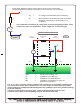
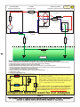
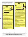
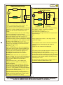
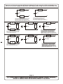
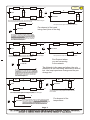
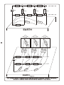
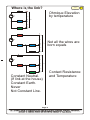
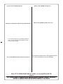
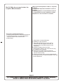
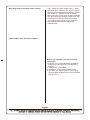
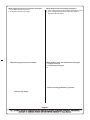
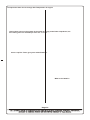
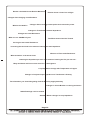
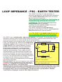
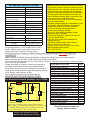
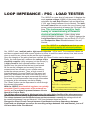
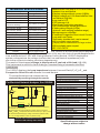
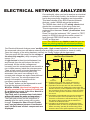
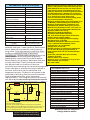
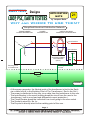
BOTTER
Designs
LOOP, PSC, EARTH TESTERS
APPLICATION
NOTE
21
by Jacques Botte
V1.00
WHY and WHERE TO USE THEM?
Simplified Electrical Distribution Network
TRANSFORMER
POWER GENERATION
L
POWER
DISTRIBUTION
USER'S BUILDING
DOMESTIC OR INDUSTRIAL
Circuit Breaker
L1
3
N
User's Socket
Es
L2
Main Circuit Breaker
and Earth Leakage
Circuit Breaker
(GFCI)
Earthing Point
of Transformer
Ns
Ls
Earthing Point
of User
Z
Earth
FIGURE 1
- At the power generator, the Neutral point of the transformer is tied to the Earth
via a cable from N to the Earthing Point of The Transformer ( Rod in the Soil ) .
- The power is distributed to the user via a cable from the transformer to the user .
- The main Breaker in the user's building break the circuit from the user to the
transformer ( built-in over-load and differential current protection ).
- The Circuit Breaker break the individual Live circuit going to the user socket .
- The Socket is wired Es, Ns, Ls
- The Es point is directly wired to the earthing point of the user .
Page 1
© COPYRIGHT 1988.....Jacques M.M.Botte ALL RIGHTS RESERVED; NO PART OF THIS SHEET MAY BE REPRODUCED, MODIFIED OR STORED
IIN A RETRIEVIAL SYSTEM, OR TRANSMITTED IN ANY FORM OR BY ANY MEAN, ELECTRONIC, MECHANICAL, PHOTOCOPYING,
RECORDING OR OTHERWISE, WITHOUT THE PRIOR WRITTEN PERMISSION OF Jacques M.M.Botte.
A “Near Real” distribution network need to take into account some others factors .
To understand it, we will replace the transformer ( Power Generator ) by the following :
L
1
Z
G
Where
Vg
=
The Voltage of the Generator (of the Transformer).
Zg
=
Internal Impedance of the Generator plus the reflected
Impedance of the Primary to the secondary of the
Transformer .
The Transformer’s impedance (ZG) change with current (winding getting warmer), Load,
Temperature, Time since maintenance. These changes are of slow moving type.
V
G
OVERVIEW OF AN ELECTRICAL INSTALLATION
N
FIGURE 2
POWER
GENERATOR
DISTRIBUTION
LINE
L
G
Z
FIGURE 3
USER
SYSTEM
Z
E
N
V
Z
Z
E2
N
E1
Z
BPE
1
Z
BPE1
BPE2
ZL
ZN
ZE1
L
G
=
=
=
=
=
BPE
2
Earth
Bonding Point Earthing "one ".
Bonding Point Earthing " two ".
Impedance of the LINE wire.
Impedance of the NEUTRAL wire.
Impedance of the Earthing wire from the
Transformer to the BPE1.
ZL ZN, ZE, etc...are in serie with contacts resistance from connections, circuit breaker, bonding points,
In a real electrical system, these impedances are part of the result of a complex electrical network
where impedances are added and subtracted dynamically (complexes, serie and/or parallel)according
to the load situation.
Temperature changes are slow moving type, contact resistance change can be very fast
(re-closure time) screws connection getting loose can also be fast some time.
Page 2
© COPYRIGHT 1988.....Jacques M.M.Botte ALL RIGHTS RESERVED; NO PART OF THIS SHEET MAY BE REPRODUCED, MODIFIED OR STORED
IIN A RETRIEVIAL SYSTEM, OR TRANSMITTED IN ANY FORM OR BY ANY MEAN, ELECTRONIC, MECHANICAL, PHOTOCOPYING,
RECORDING OR OTHERWISE, WITHOUT THE PRIOR WRITTEN PERMISSION OF Jacques M.M.Botte.
TRANSFORMER
POWER GENERATION
1
Z
Z
Line
APPLICATION
NOTE
21
by Jacques Botte
V1.00
Line 2
Z
G
L
USER'S BUILDING
DOMESTIC OR INDUSTRIAL
POWER
DISTRIBUTION
Z
Neutral 2
User's Socket
Es
V
Main Circuit Breaker
and Earth Leakage
Circuit Breaker
G
Ns
Ls
N
Z
Z
Earth 2
Neutral
Earth 1
Z
Z
Earth
FIGURE 4
What influences the Measurements off Loop/Psc/Network Analysis?
1- The Loop Impedance itself, of course (in a dynamic network, it’s changing all the time from the measurement point).
2- Temperature (Copper resistance increases with Temperature (time of the day)).
3- Load switching ON and OFF (time of the day versus loads).
4- Voltage Variation during testing (more loading on the transformer, more resistives losses.
5- Current of test (Current increase losses, and also reduce some contact losses, test current higher than reated current
of some equipment is definitively out of the question ).
6- Closure Resistance of contactors and/or circuit breakers.
7- Type of conductors used (bus bars versus wires, type of material etc . . . ).
8- Transformer quality.
9- Impedance of Bonding Points.
Total Line (Hot) Path including the transformer
Transformer from Power Utility
ZL
VG
L
User’s Board, future Load Side, Test point,
socket outlet,etc...
VL-N
Total Neutral Path
ZN
N
PSCL-N
PSCL-N
VL-E
Total Earth (Ground) Path
ZE
E
PSCL-E
ZL=Line (Hot) wire impedance including the transformer impedance.
ZN=Neutral wire impedance.
ZE=Earth (Ground) path impedance including all the connections.
PSCL-E, PSCL-N= Prospective Short Circuit Current (L to N)Page
& (L to 3
E).
VG=Electrical Network Supply Voltage Transformer (without Load).
VL-N, VL-E=Voltage between L-N & L-E (without Load).
PSCL-E
For our Analysis, we will use ZL as being the sum of all Impedances
found in the Line circuit, ZN as being the sum of all Impedances
found in the Neutral circuit, ZE as being the sum of all Impedances
found in the Earth circuit. All as Seen from the Instrument.
Simplified Network used for our Analysis
Page 3
© COPYRIGHT 1988.....Jacques M.M.Botte ALL RIGHTS RESERVED; NO PART OF THIS SHEET MAY BE REPRODUCED, MODIFIED OR STORED
IIN A RETRIEVIAL SYSTEM, OR TRANSMITTED IN ANY FORM OR BY ANY MEAN, ELECTRONIC, MECHANICAL, PHOTOCOPYING,
RECORDING OR OTHERWISE, WITHOUT THE PRIOR WRITTEN PERMISSION OF Jacques M.M.Botte.
How does a two wires Loop Tester works?
Advanced 2 Wires Ohm-Meter Principle
They are mainly using principle of an ohm-meter.
You need a stable power supply (In the case of
the conventional two wire loop tester, the power utility
supply voltage is taken as the “Reference Voltage” of
the “Ohm-Meter”.
ZL + ZE
L
VG
L
ZN
VG
VL-N
N
Internal Reference
Resistor
ZL + ZN
Loop
Tester
N
VL-E
E
IL-N
Internal Reference
Resistor
2 Wires Ohm-Meter Principle
Loop
Tester
IL-E
ZL+ZE=ZL-E = Loop Impedance Line to Earth.
PSCL-E= Prospective Short Circuit Current (L to E).
VG, =Reference Voltage (electricity supply)
E
ZE
ZL+ZN=ZL-N = Loop Impedance Line to Neutral
PSCL-N= Prospective Short Circuit Current (L to N).
VG, =Reference Voltage
The 2 wires loop Tester measure the VL-N, while
a current IL-N pass through the Internal Reference
Resistor.
The Accuracy of this Instrument depend of VG,
it’s Stability and Accuracy and the value of It’s
Internal Reference Resistor.
The Voltage at which test is performed must be
the same as the calibration voltage.
Accuracy suffer with repeated tests because the
Internal Reference Resistor heats up quickly and
it’s value increase rapidly. Display are found as
Analog and Digital. The measuring range of such
instrument is generally small.
Wires can’t be differentiated, test leads must be
moved if Line to earth Loop need to be measured.
Psc can be found on some of these instruments.
This kind of Instrument uses VG as the Reference
voltage. Vg can’t be stable ins a real dynamic
Electrical Network.
The Test Leads can’t be swapped or replaced.
If measuring with other than original Test Leads,
a error will be added or subtracted to the loop
impedance.
This kind of tester does not have a “HOLD”
facility but does not requires any battery.
Generally, a wiring check is also added to this
kind of instrument. The voltage is usually not
indicated on the display.
The Advanced 2 wires loop Tester measure the
VL-E (or VL-N if connected to L-N) voltage, while a
current IL-E pass through the Internal Reference
Resistor. This measured voltage is then compared
to the Reference Voltage. The Digital Display will
show a certain ratio which is proportional to the
measured impedance ZL+ZE.
The Accuracy of this Instrument depend of VG,
it’s Stability and Accuracy and the value of It’s
Internal Reference Resistor.
Accuracy suffer with repeated tests because the
Internal Reference Resistor heats up quickly and
it’s value increase rapidly. Display is Digital.
Wires can’t be differentiated, test leads must be
moved if Line to Neutral Loop need to be
measured.
Psc can be found on some of these instruments.
This Instrument uses VG as the Reference
voltage. Vg can’t be stable in a real dynamic
Electrical Network.
The Test Leads can’t be swapped or replaced.
If measuring with other than original Test Leads,
a error will be added or subtracted to the loop
impedance.
This kind of tester have a “HOLD” facility but does
not requires any battery (value is on “HOLD” until
the capacitor run out.
Generally, a wiring check is also added to this
kind of instrument. In some cases, the voltage is
indicated on the display.
Page 4
© COPYRIGHT 1988.....Jacques M.M.Botte ALL RIGHTS RESERVED; NO PART OF THIS SHEET MAY BE REPRODUCED, MODIFIED OR STORED
IIN A RETRIEVIAL SYSTEM, OR TRANSMITTED IN ANY FORM OR BY ANY MEAN, ELECTRONIC, MECHANICAL, PHOTOCOPYING,
RECORDING OR OTHERWISE, WITHOUT THE PRIOR WRITTEN PERMISSION OF Jacques M.M.Botte.
Microprocessor Controlled
2 Wires Ohm-Meter Principle
ZL + ZE
L
APPLICATION
NOTE
21
by Jacques Botte
V1.00
Three Wires Loop/Psc/Earth/Electrical
Network Analyzer
ZL
VG
L
IL-E
ZN
N
VL-E
Internal Load
Resistor
IL-N
VG
Loop
Tester
VL-N
ZN
E
N
PSCL-N
PSCL-N
PSCL-E
VL-E
IL-E
VN-E
ZL+ZE=ZL-E = Loop Impedance Line to Earth.
ZE
PSCL-E= Prospective Short Circuit Current (L to E).
Electrical Supply
and
Distribution
VG, =Reference Voltage (electricity supply)
The Microprocessor Controlled 2 wires loop Tester
measure VG (system Voltage) while no current is
flowing into the Internal Load Resistor of the
Tester.
It memorize that result for later use. That voltage
can also be displayed on some models.
This instrument inject a Current IL-E and measure it.
During this injection of current, not only IL-E is
measured, but the voltage VL-E (Function of IL-E) too.
The Microprocessor can then calculate the voltage
present on the impedance ZL+ZE while the current
is flowing. This voltage is V(ZL+ZE) = VG - VL-E. .
Now, the ZL+ZE can be calculated by dividing the
voltage on the impedance by the current which
circulated during the test.
ZL+ZE = V(ZL+ZE) / IL-E
Same can be repeated for the ZL+ZN impedance.
This tester does not need an Internal Reference
Resistor, only a resistor to pass enough current.
The Accuracy of this Instrument depend of VG,
it’s Stability only during the test, not It’s
Accuracy and not the value of It’s Internal
Resistor.
Accuracy does not suffer with repeated tests.
Display is Digital. Psc can be easily calculated too.
Wires can’t be differentiated, test leads must be
moved if Line to Neutral Loop need to be
measured.
This Instrument uses VG as the Reference
voltage. Vg can’t be stable in a real dynamic
Electrical Network.
The Test Leads can’t be swapped or replaced.
If measuring with other than original Test Leads,
a error will be added or subtracted to the loop
impedance. This problem can be eliminated by
the use of four wires. (Two for voltages measurement, two for current injection).
This kind of tester have a “HOLD” facility but
requires battery. Generally, a wiring check is also
added to this kind of instrument. In some cases,
the voltage is indicated on the display.
PSCL-E
E
Point of Test,
or
Socket Outlet
The Instrument measure VG while no current is flowing.
Then, inject IL-N, while IL-N is flowing, it measure
VL-N (function of IL-N)= VL-N(Fct ILN).
At the same time, it measure VN-E(Fct IL-N).
This now give us enough information to compute some
equation end get:
ZN+ZL
ZN
ZL
Now by applying the current IL-E and using a similar
method, we can get:
ZE
The Prospective Short Circuit Currents are calculated
using the previous measurement and results of
equations.
Voltage are also measured and displayed:
VL-E
VL-N
The problem of the test leads resistance remain but can
be solved using 5 or 6 wires method.
The Voltage stability of the system while testing occurs
still affect the accuracy of this instrument (like any other).
This instrument has the advantage of giving you all the
parameters of the electrical network as seen from the
instrument point of vue.
No Instrument can actually solve a Loop/Psc result in
an dynamic electrical network while in use.
Page 5
© COPYRIGHT 1988.....Jacques M.M.Botte ALL RIGHTS RESERVED; NO PART OF THIS SHEET MAY BE REPRODUCED, MODIFIED OR STORED
IIN A RETRIEVIAL SYSTEM, OR TRANSMITTED IN ANY FORM OR BY ANY MEAN, ELECTRONIC, MECHANICAL, PHOTOCOPYING,
RECORDING OR OTHERWISE, WITHOUT THE PRIOR WRITTEN PERMISSION OF Jacques M.M.Botte.
Lets have a look at an example of Electrical Network. For the purpose of this explanation, we
will use a DC power supply and Resistors and simplification using Thevenin and Kirkoff Laws.
For example, R1 and R2 could be Wires transporting electricity from the power supply to the user.
R1
Requiv. (R1+R3)
A
0.1W
A
0.2W
230V
230V
R3
B
B
0.1W
The Prospective Short Circuit between A and B
is the current which will flow from A to B if a
short circuit is made between Points A and B.
In this case, the Psc (A-B) = 230/(0.1+0.1) = 1150A
A
R1
Requiv. (R1+R3)
0.1W
A
0.2W
R2 4W
230V
The Loop resistance between A and B
is the resistance which will be seen
when measuring between Points A and B.
In this case the Loop Resistance is 0.1+0.1=0.2W
B
R3
A
Requiv. (R1+R3)
0.1W
A
0.2W
R2 20W
R3
B
By having your neighbor using his heater
(loading the system), it has the same effect of
actually lowering the voltage at the supply
utility, and also has the same effect as lowering
the loop impedance. In this case, it also has same
effect as increasing the Psc = 219.0476/0.19=1155.13A
0.1W
230V
219.0476V
B
If for example, your neighbor use a heater
which is 4 ohms, what will happen to the
Loop Impedance and the Psc?
R1
A
0.19W
R2 4W
230V
R Loop Equiv.
B
A
0.198W
R2 20W
230V
R Loop Equiv.
B
227.7227V
B
By having your neighbor using his heater
(loading the system), it has the same effect of
actually lowering the voltage at the supply
utility, and also has the same effect as lowering
the loop impedance (not as much). In this case,
it also has same effect as increasing slightly the
Psc = 227.7227/0.198=1150.114A
0.1W
If for example, your neighbor use a smaller
heater which is 20 ohms, what will happen
to the Loop Impedance and the Psc?
Page 6
© COPYRIGHT 1988.....Jacques M.M.Botte ALL RIGHTS RESERVED; NO PART OF THIS SHEET MAY BE REPRODUCED, MODIFIED OR STORED
IIN A RETRIEVIAL SYSTEM, OR TRANSMITTED IN ANY FORM OR BY ANY MEAN, ELECTRONIC, MECHANICAL, PHOTOCOPYING,
RECORDING OR OTHERWISE, WITHOUT THE PRIOR WRITTEN PERMISSION OF Jacques M.M.Botte.
A
R1
0.1W
0.1W
R2 4W
230V
A
R1
R6 4W
0.1W
V1.00
C
0.1W
R6 4W
219.0476V
D
R5
B
21
by Jacques Botte
R4
0.19W
R3
APPLICATION
NOTE
C
R4
0.1W
If for example, two neighbors, each, use a heater which is 4 ohms, what will happen
to the Loop Impedance and the Psc seen from C and D?
R Loop Equiv.
D
R5
B
0.1W
C
The equivalent circuit up to A and B look like the above
0.355353W
Psc depend of the loads
being used (time of the day)
199.5877V
D
By having two neighbors using their heaters (loading
the system), it has the same effect of actually lowering
the voltage at the supply utility, and also has the same
effect as increasing the loop impedance (mainly due to
the distance between houses). In this case, it also has
same effect as decreasing the
Psc = 199.5877/0.355353=561.66A
A
R1
C
R4
0.1W
0.1W
R3
D
R5
0.1W
0.39W
219.0476V
The Network is the same as before, the only
difference is the load being switched on and off,
but...the loop impedance change and the psc
change too.
D
By having on neighbor using it’s heaters (loading
the system) but not at the same place, has the sam
effect of actually lowering the voltage at the supply
utility, and also has the same effect as increasing
the loop impedance (mainly due to the distance
between houses). In this case, it also has same
effect as decreasing the
Psc = 219.0476/0.39=561.65A
C
R4
0.1W
R1
0.1W
R5
B
0.1W
D
B
D
If for example, the Neibog R2 is not loading the system,
what will happen to the Loop Impedance and the Psc seen
from C and D?
0.1W
C
0.3636363W
209.0909V
C
R6 4W
209.0909V
If for example, the Neibog R2 is not loading the system, what will happen
to the Loop Impedance and the Psc seen from C and D?
R Loop Equiv.
A
0.4W
R6 4W
230V
D
Psc Depend where
you are measuring
in the network.
C
A
0.1W
The equivalent circuit up to A and B look like the above
If Neighbor R6 is not at home and is gone with all the load OFF. What will happen
to the Loop Impedance and the Psc seen from C and D?
R Loop Equiv.
R5
B
0.1W
R3
0.1W
219.0476V
B
R1
C
R4
0.19W
R2 4W
230V
A
R1
By having on neighbor using it’s heaters (loading the system)
but not at the same place, has the same effect of actually
lowering the voltage at the supply utility, and also has the same
effect as increasing the loop impedance (mainly due to the
distance between houses). In this case, it also has same
effect as decreasing the Psc = 209.0909/0.3636363=575A
Psc depend of the
temperature.
D
Page 7
© COPYRIGHT 1988.....Jacques M.M.Botte ALL RIGHTS RESERVED; NO PART OF THIS SHEET MAY BE REPRODUCED, MODIFIED OR STORED
IIN A RETRIEVIAL SYSTEM, OR TRANSMITTED IN ANY FORM OR BY ANY MEAN, ELECTRONIC, MECHANICAL, PHOTOCOPYING,
RECORDING OR OTHERWISE, WITHOUT THE PRIOR WRITTEN PERMISSION OF Jacques M.M.Botte.
A
Z1
C
Z4
0.02W
E
Z7
0.02W
0.02W
230V
Z2 Load 1(W)
Z3
Z5 Load 2(W)
Z6
B
0.02W
Z9
D
0.02W
Z8 Load 3 (W)
F
0.02W
Zear
Zear
th
th
Zearth
EARTH
HOUSE 2
A
E
(W)
2(W)
Load
Z5
Z4
Z7
0.02W
0.02W
Z8N
Z5N
0.02W
Z5L
Z1
0.02W
3
Load
(W)
F
D
0.02W
Z2N
0.02W
Z2L
B
Z8
Z8L
1
Load
0.02W
Z2
0.02W
HOUSE 3
C
0.02W
HOUSE 1
230V
Z6
Z9
0.02W
0.02W
Ze
a
rth
Z3
0.02W
a
Ze
rth
th
r
Zea
EARTH Page 8
© COPYRIGHT 1988.....Jacques M.M.Botte ALL RIGHTS RESERVED; NO PART OF THIS SHEET MAY BE REPRODUCED, MODIFIED OR STORED
IIN A RETRIEVIAL SYSTEM, OR TRANSMITTED IN ANY FORM OR BY ANY MEAN, ELECTRONIC, MECHANICAL, PHOTOCOPYING,
RECORDING OR OTHERWISE, WITHOUT THE PRIOR WRITTEN PERMISSION OF Jacques M.M.Botte.
Where isL the link?
ZL
ZN
N
21
by Jacques Botte
V1.00
Ohmique Elevation
by temperature
VL-N
VG
APPLICATION
NOTE
VL-E
VN-E
ZE
E
L
ZL
VL-N
VG
Z N1
Z N2
N
VL-E
Not all the wires are
born equals
VN-E
ZE
E
L
Z L1
VL-N
VG
Z L2
Z N2
N
VL-E
VN-E
ZE
E
Constant Neutral.
(If link at the house)
Constant Earth.
Never
Not Constant Line.
Contact Resistance
and Temperature
Page 9
© COPYRIGHT 1988.....Jacques M.M.Botte ALL RIGHTS RESERVED; NO PART OF THIS SHEET MAY BE REPRODUCED, MODIFIED OR STORED
IIN A RETRIEVIAL SYSTEM, OR TRANSMITTED IN ANY FORM OR BY ANY MEAN, ELECTRONIC, MECHANICAL, PHOTOCOPYING,
RECORDING OR OTHERWISE, WITHOUT THE PRIOR WRITTEN PERMISSION OF Jacques M.M.Botte.
Can you trust a Measurement?
What is the 1826NA actually do?
Changes on Impedance after wiring modifications.
What is the 1826NA actually don’t do?
In a normal network, the internal Impedance
of the source limit the total available current
from the power supply.
Is Loop/Psc Measurement useful for anyone?
The closer to the source, the higher the Psc.,
Or the more the psc you should get.
Web: HTTP://WWW.SEW.COM.TW E-Mail: [email protected]
Page 10
© COPYRIGHT 1988.....Jacques M.M.Botte ALL RIGHTS RESERVED; NO PART OF THIS SHEET MAY BE REPRODUCED, MODIFIED OR STORED
IIN A RETRIEVIAL SYSTEM, OR TRANSMITTED IN ANY FORM OR BY ANY MEAN, ELECTRONIC, MECHANICAL, PHOTOCOPYING,
RECORDING OR OTHERWISE, WITHOUT THE PRIOR WRITTEN PERMISSION OF Jacques M.M.Botte.
Why is the Earth Impedance stable in a dynamic
network?
1- Good Earth Impedance should be as low as
possible.
2- Earth Impedance is not switched on and off.
3- Unlike Neutral and Line impedances, Earth
Impedance is near Constant in a network.
But !!!!! Why do you need to take the
Loop/Psc Measurement?
Three wires methods advantages?
1- Similar problems with the Test Leads Resistance
2- Temperature Problem of Internal Resistance
does not influence the measurement.
3- Multivoltage.
1- Temperature of Internal Resistors.
2- Calibration of the Instrument.
3- Test Leads Resistance is an error (can be
calibrated with the supplied test leads, but
any use of other test leads requires a new
Calibration).
4- Operating Voltage need to be fixed.
(Fixed system voltage). The Instrument can only
be calibrated at one voltage.
5- Results are too stable to be true (using an
averaging integrating method which is related to
the Sine versus of time.
6- Impedances and/or Wiring can’t be differentiated,
we only get the sum of Line and Neutral or Line and
Earth Impedances.
Page 11
© COPYRIGHT 1988.....Jacques M.M.Botte ALL RIGHTS RESERVED; NO PART OF THIS SHEET MAY BE REPRODUCED, MODIFIED OR STORED
IIN A RETRIEVIAL SYSTEM, OR TRANSMITTED IN ANY FORM OR BY ANY MEAN, ELECTRONIC, MECHANICAL, PHOTOCOPYING,
RECORDING OR OTHERWISE, WITHOUT THE PRIOR WRITTEN PERMISSION OF Jacques M.M.Botte.
Why I don’t believe repeated stable readings
The 2 wires loop Tester measure the VG, store
that value into a capacitor, then injects a current
through it’s Internal Reference Resistor, measure
that voltage VL-N while the current is passing
through the loop, stores it into an other capacitor
then uses these two voltages to work out a ratio
compared to the Internal Reference Resistor.
The working Voltage range is very small, the
Internal Reference Resistor change with
repeated tests
What happen when the Load Changes?
How do you calibrate a two wire Loop/Psc
instrument?
1-Impedance of Line and Reflected impedance
Transformer upstream of the Transformer is
unknown.
2- Voltage may not be stable.
3- Resistance of test Leads must be known.
4- Current is very high in general, much higher
the than rated equipment in the circuit (sockets,
switches, etc...).
Page 12
© COPYRIGHT 1988.....Jacques M.M.Botte ALL RIGHTS RESERVED; NO PART OF THIS SHEET MAY BE REPRODUCED, MODIFIED OR STORED
IIN A RETRIEVIAL SYSTEM, OR TRANSMITTED IN ANY FORM OR BY ANY MEAN, ELECTRONIC, MECHANICAL, PHOTOCOPYING,
RECORDING OR OTHERWISE, WITHOUT THE PRIOR WRITTEN PERMISSION OF Jacques M.M.Botte.
What happen when the Test Current Changes?
1- If the Test Current is too Low.
2- If the Test Current is too High.
Why Averaging of results is useless.
What happen when the Voltage Changes?
1- If the voltage during load if higher than before Load.
2- If the voltage during load is lower than what is
should be due to losses.
What happen when the Temperature Changes?
1- Copper changes
2- Transformer changes
3-
Current sensing problems in general?
You’ll be the Judge
Page 13
© COPYRIGHT 1988.....Jacques M.M.Botte ALL RIGHTS RESERVED; NO PART OF THIS SHEET MAY BE REPRODUCED, MODIFIED OR STORED
IIN A RETRIEVIAL SYSTEM, OR TRANSMITTED IN ANY FORM OR BY ANY MEAN, ELECTRONIC, MECHANICAL, PHOTOCOPYING,
RECORDING OR OTHERWISE, WITHOUT THE PRIOR WRITTEN PERMISSION OF Jacques M.M.Botte.
Prospeective Short Circuit change with Temperature of Copper.
Having more users on the system is the same as having a total lower impedance, but
also having less Psc available per user too...or isn’t?.
Can a Loop/Psc Tester give you a stable Reading?
What is the 1825LP?
Page 14
© COPYRIGHT 1988.....Jacques M.M.Botte ALL RIGHTS RESERVED; NO PART OF THIS SHEET MAY BE REPRODUCED, MODIFIED OR STORED
IIN A RETRIEVIAL SYSTEM, OR TRANSMITTED IN ANY FORM OR BY ANY MEAN, ELECTRONIC, MECHANICAL, PHOTOCOPYING,
RECORDING OR OTHERWISE, WITHOUT THE PRIOR WRITTEN PERMISSION OF Jacques M.M.Botte.
Results calculated Versus Results Meeasured.
Results shows a lower Psc at Night.
Changes after changing circuit Breakers.
Changes after screwing contact points and connection points.
What is the 1824LP?
Changes in Transformers Internal Impedance.
Changes test Lead Resistance
What can our 1826NA tell you?
Two Wires testers Can’t be Trusted.
Solving the test Leads Resistance.
Increasing the total load is the same as lowering the total impedance.
Influence of Test Leads Resistance.
What and when is the worst Case?
Lowering the impedance per user is the same as lowering the Psc per user too. .
Many Accidents and fires occurs when Psc is the highest.t.
Loop Impedance change with Temperature of Copper.
Changes in Projected input Impedance on Transformer’s Primary.
The Information you should be getting from the Elctricity supply Authoirty
Changes in Circuit Breaker re-closing resistance
Stable Readings can’t be trusted.
Summer / Winter changes in Loop Impedance.
Page 15
© COPYRIGHT 1988.....Jacques M.M.Botte ALL RIGHTS RESERVED; NO PART OF THIS SHEET MAY BE REPRODUCED, MODIFIED OR STORED
IIN A RETRIEVIAL SYSTEM, OR TRANSMITTED IN ANY FORM OR BY ANY MEAN, ELECTRONIC, MECHANICAL, PHOTOCOPYING,
RECORDING OR OTHERWISE, WITHOUT THE PRIOR WRITTEN PERMISSION OF Jacques M.M.Botte.
LOOP IMPEDANCE - PSC - EARTH TESTER
The 1824LP is the first of a new generation of
electrical instruments for testing electrical installations.
It has a built-in Earth tester which does not require
the use of poles or long wires.
This instrument is useful for fault-finding or
commissioning of Domestic electrical
installations. This new instrument uses a three
wires unique principle of operation.
It displays the main system voltage of the power
utility, without loading the wiring.
The 1824LP displays the Loop Impedance
between Line and Earth (ZL+ZE)=ZL-E and Prospective
Short Circuit between Line and Neutral.
••••••••The 1824LP is so simple to use that you can
focus on solving rapidly the electrical problem
instead of having to study the instruction manual.••••••
Our 1824LP uses “multiple paths high current injection “ for it’s tests. The measured values are
well above network noise and that current injection is closer to real life current values, thus, test
occurs close to real life use, where results are the most important.
Once the integrity of the wiring has been verified, the “Smart” button can be depressed.
Firstly, the instrument will measure the voltage of the
L
1824LP
ZL
electricity supplier (utility company) at the source(VG).
A high current is then injected between Line and
Neutral from the point where the test is performed.
VG
VL-N
PSCL-N
All the results (voltages and currents) from this
measurement are stored in a non volatile memory
N
inside the microprocessor. Then, a high current is
ZN
injected between Line and Earth from the same test
point (fully automated, the user’s has nothing to do),
currents and voltages are again measured and stored.
E
From now, the microprocessor has enough information
ZE
to compute all the necessary results to display.
ZE= Earth Resistance, Spike resistance.
The “Smart” button can be depressed to scroll through
the relevant information.
ZL+ZE=ZL-E = Loop impedance.
With the 1824LP, the electrical engineer can quickly
PSCL-N= Prospective Short Circuit Current (L to N).
ascertain if basic components of the network are
VL-N, =Main Voltage (without Load).
healthy or if a problem is present between Line to
Neutral, Line to Earth or in the Earth path.
The Earth path is measured and calculated without the need for poles or long wires to be used.
The Earth path shown on the instrument is exactly what the earth current will be going through.
Prospective Short Circuit Current between Line-Neutral and Loop Impedance between
Line-Earth are displayed as well as Earth Spike Resistance.
PSCL-N
TECHNICAL SPECIFICATION
Loop Impedance Range L-E
0.08-2000V (Software Ctrl)
Test Currents in Each Loop
11.76A @ 230V/50HZ
Voltage Measurement L-N,L-E
50 to 280V AC (Sine)
•Measures Earth Resistance without the need for
poles in the ground or external measuring wires.
•Earth Measurement uses the real earth current
path and the current generated by the electric
network, without the need for any disconnection.
•The displayed Earth Resistance is exactly the
earth resistance that the earth current will need
to go through if an earth fault occurs.
(You do not need to add all the bonding points
and connection paths).
•Displays voltage supply at the transformer (Line
to Neutral), without loading the transformer.
•Single One Smart Push button operation;
ON, Scroll through results and menus.
•Checks wiring integrity (LEDs).
• Auto-off / Auto-ranging (software range).
•Microprocessor controlled.
•Combined Prospective Short circuit Current,
Loop and Earth Tester.
•Loop test for L-E and PSC between L-N.
•Voltage test L-N .
•Test leads, shoulder belt, user’s manual.
•60HZ available upon request.
•Display can be customized for large orders.
•60Hz available upon request.
•IEC 1010 CAT. III.
Earth Wire/Path Return Resistance 0.03-2000V (Software Ctrl)
Neutral Wire Resistance
Only available with 1826NA
Line Wire Resistance &
Only available with 1826NA
Transformer Windings
PSC Current (L-N) Max
3KA@230Vac supply
PSC Current (L-E) Max
Only available with 1826NA
Operating Voltage
230V ¡Ó±50% @50Hz Sine
Dimensions (LxWxD)
(170x165x92)mm
Weight
970g
Power Source
8 x AA Batteries
Typical Accuracy
Loop Impedance
6% of FS ¡Ó±2 dgt
PSC Current
15% of FS ¡Ó±5 dgt
Voltage
3% of FS ¡Ó±1 dgt
Operating-Temperature
-Humidity
-10 OC to + 40 OC
80% max relative humidity
The 1824LP is the first portable electrical
Loop Impedance / PSC tester which has a
built-in Earth tester, and which does not
require the use of poles or long wires.
This instrument is useful for fault-finding or commissioning of domestic electrical
installations.
Appreciating the Earth(ground) path by reading its value has never been easier.
Bad contacts, old wiring or bad earth path can be identified.
Faulty electrical network can be resolved in a fraction of the time normally required using
conventional equipment.
1824LP
PERFORMANCE SELECTOR
Down time due to a faulty electrical network is
•
Wiring OK Indication
minimal as the fault can be identified quickly.
•
Reversed Wiring Indication
Find which loop need to be attended to and why.
•
Smart Control One Push Button
(find those old wires with high impedance before
•
Microprocessor Controlled
a fire starts, and replace them).
•
CMOS Low Consumption
The simplified electrical network can be
•
Display System Voltage (Line to Neutral)
deducted by scrolling through the results.
1826NA
Display Line Path Impedance
For Electrical Network Analazys, See 1826NA
Total Line (Hot) Path including the transformer
Transformer from Power Utility
ZL
VG
L
User’s Board, future Load Side, Test point,
socket outlet,etc...
VL-N
Total Neutral Path
ZN
N
1826NA
PSCL-N
PSCL-N
PSCL-E
VL-E
Total Earth (Ground) Path
ZE
E
PSCL-E
ZL=Line (Hot) wire impedance including the transformer impedance.
ZN=Neutral wire impedance.
ZE=Earth (Ground) path impedance including all the connections.
PSCL-E, PSCL-N= Prospective Short Circuit Current (L to N) & (L to E).
VG=Electrical Network Supply Voltage Transformer (without Load).
VL-N, VL-E=Voltage between L-N & L-E (without Load).
Please note: Instrument accuracy
depend of VG stability while testing.
1826NA
•
•
1826NA
•
•
•
•
Auto-Off Function
•
Test Leads Compartment In The Case
•
Retractable Handle
•
Color Coded Test Leads
1826NA
Display Voltage Line to Earth
Two wire operation Line to Earth possible 1826NA
•
Strap and Battery Supplied
•
Very Low Consumption
Display Neutral Path Impedance
Display Earth Path Impedance
Display Prospective Short Circuit L-N
Display Prospective Short Circuit L-E
Re-scroll Through Previous Results
Bat. OK / Low Battery Indicator
Scroll Through Previous Results
Specifications are subject to
change without notice.
LOOP IMPEDANCE - PSC - LOAD TESTER
The 1825LP is a new kind of instrument. It displays the
main system voltage (V@0A) of the power utility and
calculates the volt drop between Line and Neutral as
if 16A was flowing between Line to Neutral. The builtin Load Tester does not require the use of heavy high
power resistor elements to measure the “On-Load” volt
drop. This instrument is useful for fault-
finding or commissioning of Domestic
electrical installations. It has a three wires
unique principle of operation. The 1824LP displays the
Loop Impedance between Line and Earth (ZL+ZE)=ZL-E
and Prospective Short Circuit between Line and
Neutral.
••••••••The 1825LP is so simple to use that you can
focus on solving rapidly the electrical problem
instead of having to study the instruction manual.••••••
Our 1825LP uses “multiple paths high current injection “ for its tests. The measured values are
well above network noise and current injection is closer to real life current values, thus, test occurs
close to real life use, where results are the most important.
Once the integrity of the wiring has been verified, the “Smart” button can be depressed.
Firstly, the instrument will measure the voltage of the
L
1825LP
ZL
electricity supplier (utility company) at the source(VG).
A high current is then injected between Line and
Neutral from the point where the test is performed.
VG
VL-N
PSCL-N
16A
All the results (voltages and currents) from this
measurement are stored in a non-volatile memory
N
inside the microprocessor. Then, a high current is
ZN
injected between Line and Earth from the same test
point (fully automated, the user’s has nothing to do),
currents and voltages are again measured and stored.
E
From now, the microprocessor has enough information
ZE
to compute all the necessary results to display.
VL-N, =Main Voltage (with Load=V@16A).
The “Smart” button can be depressed to scroll through
the relevant information.
ZL+ZE=ZL-E = Loop impedance.
With the 1825LP, the electrical engineer can quickly
PSCL-N= Prospective Short Circuit Current (L to N).
ascertain if basic components of the network are
VL-N, =Main Voltage (without Load=V@0A).
healthy or if a problem is present between Line to
Neutral or Line to Earth.
The Voltage after volt drop is displayed using the calculation facility of the microprocessor
without the need for heavy, high power electrical elements.
The voltage between Line and Neutral shows on the instrument is exactly the voltage which will
be measured between Line and Neutral if 16A flows between those two points.
Prospective Short Circuit Current between Line-Neutral and Loop Impedance between
Line-Earth are displayed as well as the resulting voltage between Line and Neutral, just as if
16A was taken from Line-Neutral.
PSCL-N
TECHNICAL SPECIFICATION
Loop Impedance Range L-E
0.08-2000V (Software Ctrl)
Test Currents in Each Loop
11.76A @ 230V/50HZ
•Measures the volt drop as if 16A was flowing
between Line and Neutral.
•Displays voltage without current (V@0A).
•Display voltage as if 16A flows between Line
and Neutral (V@16A).
•Loop test for L-E.
•PSC between L-N.
•One Smart Push button operation;
ON, Scroll through results and menus.
•Checks wiring integrity (LEDs).
• Auto-off / auto-ranging (software range).
•Microprocessor controlled.
•Combined Prospective Short circuit Current,
Loop and Load Tester.
•Test leads, shoulder belt, user’s manual.
•60HZ available upon request.
•Display can be customized for large orders.
•60Hz available upon request.
•IEC 1010 CAT.III.
Voltage Measurement (0A - 16A) 50 to 280V AC (Sine)
Earth Wire/Path Return Resistance Not available on this model
Neutral Wire Resistance
Only available with 1826NA
Line Wire Resistance &
Only available with 1826NA
Transformer Windings
PSC Current (L-N) Max
3KA@230Vac supply
PSC Current (L-E) Max
Only available with 1826NA
Operating Voltage
230V ¡Ó±50% @50Hz Sine
Dimensions (LxWxD)
(170x165x92)mm
Weight
970g
Power Source
8 x AA Batteries
Typical Accuracy
Loop Impedance
6% of FS ¡Ó±2 dgt
PSC Current
15% of FS ¡Ó±5 dgt
Voltage
3% of FS ¡Ó±1 dgt
Operating-Temperature
-Humidity
-10 OC to + 40 OC
80% max relative humidity
The 1825LP is an instrument which displays
the main system voltage (V@0A) of the power utility and calculates the volt drop between
Line and Neutral as if 16A was flowing between Line to Neutral. 1825LP displays the
system voltage minus the voltage lost into the Line and Neutral impedances (lost
due to the current circulating into these impedances).
The result of this dropped voltage is displayed as if you had a 16A load (V@16A).
This instrument is useful for fault-finding or commissioning of domestic electrical
installations.
The 1825LP displays the Loop Impedance between Line and Earth (Z L+Z E)=Z L-E and
Prospective Short Circuit between Line and Neutral.
The simplified electrical network can be
deducted by scrolling through the results.
For Electrical Network Analyzer, See 1826NA
Total Line (Hot) Path including the transformer
Transformer from Power Utility
ZL
VG
L
User’s Board, future Load Side, Test point,
socket outlet,etc...
VL-N
Total Neutral Path
ZN
N
1826NA
PSCL-N
PSCL-N
PSCL-E
VL-E
Total Earth (Ground) Path
ZE
E
PSCL-E
ZL=Line (Hot) wire impedance including the transformer impedance.
ZN=Neutral wire impedance.
ZE=Earth (Ground) path impedance including all the connections.
PSCL-E, PSCL-N= Prospective Short Circuit Current (L to N) & (L to E).
VG=Electrical Network Supply Voltage Transformer (without Load).
VL-N, VL-E=Voltage between L-N & L-E (without Load).
Please note: Instrument accuracy
depend of VG stability while testing.
PERFORMANCE SELECTOR
Wiring OK Indication
Reverse Wiring Indication
Smart Control One Push Button
Microprocessor Controlled
CMOS Low Consumption
Display System Voltage (Line to Neutral)
Display Line Path Impedance
Display Neutral Path Impedance
Display Earth Path Impedance
Display Prospective Short Circuit L-N
Display Prospective Short Circuit L-E
Re-scroll through previous results
Bat. OK / Low Battery Indicator
Scroll Through Previous Results
Auto-Off Function
Test Leads Compartment In The Case
Retractable Handle
Color Coded Test Leads
Display Voltage Line to Earth
Two Wire Operation Line to Earth Possible
Strap and Battery Supplied
Very Low Consumption
1825LP
•
•
•
•
•
•
1826NA
1826NA
1826NA
•
1826NA
•
•
•
•
•
•
•
1826NA
1826NA
•
•
Specifications are subject to
change without notice.
ELECTRICAL NETWORK ANALYZER
Conventionally, when you had to analyze an electrical
network or find a fault quickly, the electrical engineer
had to buy many bulky expensive test instruments.
This latest release of the SEW Electrical Network
Analyzer, model 1826NA solves that problem.
The 1826NA has a built-in LED wiring check which
checks the correctness of the wiring under test.
This microprocessor controlled, superb piece of
equipment that has one “Smart” push button -does
it all- type.
Press it to turn the instrument “ON”, press it to TEST,
press it to SCROLL through the results, press it to
scroll through PREVIOUS results or press it to
START an other test.
••••••••The 1826NA is so simple to use that you can
focus on solving rapidly the electrical problem
instead of having to study the instruction manual.••••••
Our Electrical Network Analyzer uses “multiple paths high current injection “ for its test so that
the measured values are well above network noise and high current injection is closer to reality.
Once the integrity of the wiring has been verified, the “Smart” button can be depressed.
The instrument will first measure the voltage of
Fault Finding and Analyzing
the electricity supplier (utility company) at the
the Electrical Network
L
source. (VG).
ZL
A high current is then injected between Line
and Neutral from the point where the test is
VG
VL-N
PSCL-N
performed. All the results (voltages and
currents) from this measurement are stored in a
N
non volatile memory inside the microprocessor.
ZN
PSCL-E
Then, a high current is injected between Line
VL-E
and Earth from the same test point (fully
automated, the user’s has nothing to do),
E
currents and voltages are again measured and
ZE
stored. From now, the microprocessor has
Electrical Supply
Point of Test,
and
or
enough information to compute all the
Distribution
Socket Outlet
necessary results to display.
VG = Voltage of the generator (supply transformer)
The “Smart” button can be depressed to scroll
(internal impedance of transformer = X-Form)
through the relevant information.
ZL = Impedance of the Line wire from the transformer,
up to the test point (ZL displayed by Instrument also
With the 1826NA, the electrical engineer can
includes X-Form). If this impedance is too high, check
quickly ascertain if the network is healthy or
the connections of the Line wiring, check the quality
if a problem is present in the Line, Neutral or
of the line wiring and the switches / contacts in the
Earth path of the network.
line circuit.
The Earth path is measured and calculated
ZN = Impedance of the Neutral wire from the transformer,
without the need for poles or long wires.
up to the test point. If this impedance is too high,
check the connections of the Neutral wiring, check
The Earth path shown on the instrument is
the quality of the line wiring and the switches or
exactly what the earth current will be going
contacts in the Neutral circuit.
through. Prospective Short Circuit Current
ZE = Impedance of the Earth wire, including the Earth
and Loop Impedance between Line-Neutral
Impedance itself, as seen by the protection system.
and Line-Earth and all their components are
Similar checking, specially at the bounding points
should be done is this path impedance is too high.
displayed.
PSCL-N
PSCL-E
TECHNICAL SPECIFICATION
Loop Impedance Range L-E,L-N
0.03-2000W (Software Ctrl)
Test Currents in Each Loop
11.76A @ 230V/50HZ
Voltage Measurement L-N,L-E
50 to 280V AC (Sine)
•Measures Earth Resistance without the need for
poles in the ground or external measuring wires.
•Earth Measurement uses the real earth current
path and the current generated by the electric
network, without the need for any disconnection.
•The Earth Resistance displayed is exactly the
earth resistance that the earth current will need
to go through if an earth fault occurs.
(You do not need to add all the bonding points
and connection paths resistances)
•Displays voltage supply at the transformer (Line
to Neutral), without loading the transformer.
•Displays voltage between Line(Phase) and
Earth(Ground), without drawing any current.
•Measures the Impedance of the Line itself, so
you can analyze and differentiate between the
multiples paths of the wiring.
•Measures the Neutral Impedance.
•One Smart Push button operation;
ON, Test, Scroll through results and menus.
•Checks wiring integrity (LEDs).
• Auto-off / auto-ranging (software ranging).
•Microprocessor controlled.
•Combined Prospective Short circuit current,
Loop, individual wire and Earth Tester.
•Loop test for L-E, L-N and PSC.
•Voltage test L-N and L-E.
•Enables analysis of constituent components
in L-E and L-N loops giving resistance of
earth, neutral wire, live wire and transformer
winding.
•Test leads, shoulder belt, user’s manual,
batteries included.
•60HZ available upon request.
•Displays can be customized for large orders.
•60Hz available upon request.
•IEC 1010 CAT.III.
Earth Wire/Path Return Resistance 0.01-2000W (Software Ctrl)
Neutral Wire Resistance
0.01-2000W (Software Ctrl)
Line Wire Resistance &
0.01-2000W (Software Ctrl)
Transformer Windings
PSC Current (L-N) Max
6KA@230Vac supply
PSC Current (L-E) Max
6KA@230Vac supply
Operating Voltage
230V ¡Ó±50% @50Hz Sine
Dimensions (LxWxD)
(170x165x92)mm
Weight
970g
Power Source
8 x AA Batteries
Typical Accuracy
Loop Impedance
4% of FS ¡Ó±2 dgt
PSC Current
10% of FS ¡Ó±5 dgt
Voltage
2% of FS ¡Ó±1 dgt
Operating-Temperature
-Humidity
-10 OC to + 40 OC
80% max relative humidity
The 1826NA is the first portable electrical
network analyzer. It has a built-in Earth tester
which does not requires the use of poles or
long wires. This instrument is useful for faultfinding or commissioning of electrical
installations. Differentiating between the Line
(hot), Neutral and Earth(ground) path by
reading their values has never been easier.
Bad contacts, old wiring or bad earth path are
quickly identified. Faulty electrical network
can be resolved in a fraction of the time
normally required using conventional equipment.
Down time due to a faulty electrical network is
minimal as the fault can be identified and
diagnosed quickly. Find which wire need to be
attended to and why (find those old wires with
high impedance before a fire starts and
replace them). The complete electrical network
can be analyzed by scrolling through the results.
Total Line (Hot) Path including the transformer
Transformer from Power Utility
ZL
VG
L
User’s Board, future Load Side, Test point,
socket outlet,etc...
VL-N
Total Neutral Path
ZN
N
1826NA
PSCL-N
PSCL-N
PSCL-E
VL-E
Total Earth (Ground) Path
ZE
E
PSCL-E
ZL=Line (Hot) wire impedance including the transformer impedance.
ZN=Neutral wire impedance.
ZE=Earth (Ground) path impedance including all the connections.
PSCL-E, PSCL-N= Prospective Short Circuit Current (L to N) & (L to E).
VG=Electrical Network Supply Voltage Transformer (without Load).
VL-N, VL-E=Voltage between L-N & L-E (without Load).
Please note: Instrument accuracy
depend of VG stability while testing.
1826NA
•
•
•
•
•
•
•
•
•
•
•
•
•
•
•
Auto-Off Function
•
Test Leads Compartment In The Case
•
Retractable Handle
•
Color Coded Test Leads
•
Display Voltage Line to Earth
•
Two wire operation Line to Earth possible
•
Strap and Battery Supplied
•
Very Low Consumption
PERFORMANCE SELECTOR
Wiring OK Indication
Reverse Wiring Indication
Smart Control One Push Button
Microprocessor Controlled
CMOS Low Consumption
Display System Voltage (Line to Neutral)
Display Line Path Impedance
Display Neutral Path Impedance
Display Earth Path Impedance
Display Prospective Short Circuit L-N
Display Prospective Short Circuit L-E
Re-scroll Through Previous Results
Bat. OK / Low Battery Indicator
Scroll Through Previous Results
Specifications are subject to
change without notice.