1
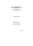
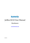
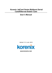
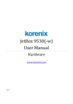
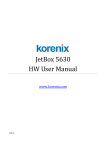
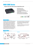
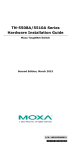
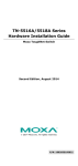
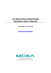
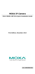
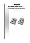
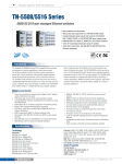
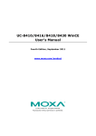
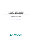
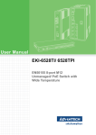
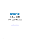
 JetBox9462‐w
UserManual
Hardware
www.korenixembedded.com
Copyright© 2010 Korenix Technology Co., Ltd. All rights reserved. Reproduction without permission is prohibited. Information provided in this manual is intended to be accurate and reliable. However, the original manufacturer assumes no responsibility for its use, or for any infringements upon the rights of third parties that may result from its use. The material in this document is for product information only and is subject to change without notice. While reasonable efforts have been made in the preparation of this document to assure its accuracy, Korenix assumes no liabilities resulting from errors or omissions in this document, or from the use of the information contained herein. Korenix reserves the right to make changes in the product design without notice to its users. Korenix is a registered trademark of Korenix Technology Co., Ltd. All other trademarks or registered marks in the manual belong to their respective manufacturers. The advantage of adopting Korenix JetBox series is ready‐to‐use. Korenix is devoted to improve the usability of embedded computer in industrial domain. Besides operating system, Korenix provides device drivers, protocol stacks, system utilities, supporting services and daemons to make system integration simple. Further, Korenix provides application development toolkits for users to build up their own applications easily. The stylish JetBox 9400 series is an industrial layer‐3 router with Linux computing. It is a gateway to connect different network groups (Ethernet, fieldbus, serial or IO control) in a complex networking architecture and manage peripherals at the front‐end site through its Linux programs or Java applications. It is reliable (network redundancy, system recovery) and robust (passive cooling, protected against the dusts and spills, shock & vibration resistance) to adopt in severe industrial vertical markets, such as transportation, substation, or hazardous environment. Feature JetBox9462‐w Processor Intel Xscale IXP435 667MHz RISC‐based Fanless System memory 128MB DDR2 RAM System flash 32MB Ethernet 10/100 Base‐Tx RJ45 connector x5 Storage SD card slot x1 CF card slot x1 Mobile slot miniPCIe x1 SIM x1 Serial port RS232/422/485 x4 (DB37 connector) with long distance termination switches (internal), default RS232 USB USB 2.0 x3 (Host) USB Supporting devices USB flash, wireless dongle Digital IO 8 DIO (default 8 DI), DI or DO is defined by customers Console port 3‐pin header (RS232 interface) LED per Ethernet port (on Link/Activity (Green on/Green blinking) the port) Full Duplex/Collision (Yellow on/ Yellow blinking) LED per unit Power on/off x1 (Green on/off) Reset Button x1 HW Watchdog timer Generates a time‐out system reset, 1 sec Power supply DC 12~48V Power Consumption 25W OS support Embedded Linux 2.6.20 Construction Rugged Aluminum Alloy Chassis, IP31 protection Color Silver Mounting Wall mount Dimensions 66.5(H) x 250(W) x 106.3(D) mm Net Weight 1.07kg Operating Temp. ‐40 ~ 176℉(‐40 ~ 80℃)**, 5 to 95% RH Storage Temp. ‐40 ~ 176℉(‐40 ~ 80℃), 5 to 95% RH Regulation FCC class A, CE, UL* EN55022 class A EN55024 EN61000‐3‐2, 3 EN61000‐4‐2, 3, 4, 5, 6, 8, 11 IEC 60950 IEC61373* (Railway) EN50155* (Railway) EN50121‐4* (Railway) NEMA TS2* (traffic control) Shock IEC60068‐2‐27 (50g peak acceleration) Vibration IEC60068‐2‐6 (5g/ 10~150Hz/ operating) MTBF greater than 200,000 hours@25℃ Warranty 5 years *Optional **Safety information for UL: ‐ Maximum Surrounding Air Temperature 65℃ ‐ For use in Pollution Degree 2 Environment JetBox9462‐w appearance JetBox9462‐w mechanical outline The JetBox comes with a Phoenix connector that carries a 12~48V DC external power input. Pin
Power Signal Name
1
VCC
2
GND
‐
‐
Use Copper Conductors Only, Tighten to 4.5 lb in The wire gauge to the terminal block should be in the range between 12~28 AWG This switch is used to turn the system power on or off. The LED indicators show their Active/Link status (Green blinking/ Green on) and Col/Fdx status (Yellow on/ blinking). This LED indicator is used to indicate the power on / off status. Power on/off: Green on/ off Standard RJ‐45 jack sockets. Pin
10/100 Base-T Signal Name
1
RX+
2
RX-
3
TX+
4
5
6
TX-
7
8
USB type “A” female connectors for USB peripherals Pin USB Signal Name 1 VCC 2 DATA‐ 3 DATA+ 4 GND The JetBox provides one Console port 3‐pin connector for debug use. Console
1
TXD
2
RXD
3
GND
This button is used to reset the CPU causing the system reboot or reset to the factory default. Press 3 seconds for system reboot. Press 7 seconds to reset the JetBox to the factory default. This socket is used for the type I/II CF Card and reserved for system extension. This socket is used for a SD Card and is for the users’ applications. There is a external blanket to cover the SD card slot. The JetBox supports 8 digital channels and users can configure them as digital outputs or digital inputs. Following is the connector pin assignments. (The default setting is digital input) Digital input Below figures show 2 ways to use digital input function. The digital input channels can support max. 5V. Dry connect for digital input Wet connect for digital input Digital Output Below figure shows how to use digital output function. The digital output channels can support max. 3.3V. The JetBox is available with GSM/ GPRS/ EDGE/ 3G/ HSDPA/ HSUPA module via its internal miniPCIe connector (the signal is the same as USB signal) Pin Signal name Description Input/Output Active State Voltage Levels Min Typ Max
1 NC No connect 2 VCC 3.3 V supply Input Power 3.00 3.30 3.60 3 NC No connect 4 GND Ground GND GND 5 NC No connect 6 NC No connect 7 NC No connect 8 USIM_PWR USIM VCC supply
Output (1.8 V) Power 1.60 1.80 1.90 2.70 3.00 3.30 Output (3.0 V) 9 GND Ground GND GND 10 USIM_DATA USIM I/O pin Input High (1.8 V) Low 1.20 2.10 Input Low (1.8 V) 0.00 0.63 Output High (1.8
1.30 1.80 2.10 Output Low (1.8 V)
0.00 0.30 Input High (3.0 V) 1.95 3.30 Input Low (3.0 V) 0.00 1.05 Output High (3.0
2.10 3.00 3.30 0.00 0.40 V) V) Output Low (3.0 V)
11 NC No connect 12 USIM_CLK USIM clock Output High (1.8
High 1.30 1.80 2.10 0.00 V) Output Low (1.8 V)
0.47 Pin Signal name Description Input/Output Active State Output High (3.0
Voltage Levels Min Typ Max
1.90 3.00 3.30 V)
Output Low (3.0 V)
0.00 0.60 13 NC No connect 14 USIM_RESET USIM reset Output High (1.8
Low 1.30 1.80 2.10 Output Low (1.8 V)
0.00 Output High (3.0
2.20 3.00 3.30 0.00 0.70 V) 0.47 V)
Output Low (3.0 V)
15 GND Ground GND GND 16 NC No connect 17 NC No connect 18 GND Ground GND GND 19 NC No connect 20 W_DISABLE# Wireless disable Input High Low 2.30 3.30 3.60 0.90 Input Low 21 GND Ground GND GND 22 NC No connect 23 NC No connect 24 VCC 3.3 V supply Input Power 3.00 3.30 3.60 25 NC No connect 26 GND Ground GND GND 27 GND Ground GND GND 28 NC No connect 29 GND Ground GND GND 30 NC No connect 31 NC No connect 32 NC No connect 33 NC No connect 34 GND Ground GND GND 35 GND Ground GND GND 36 USB_D- USB data
Input High 2.00 3.00 3.60 negative(Low/Full
Input Low 0.00 2.00 Pin Signal name Description speed) Input/Output Active State Voltage Levels Min Typ Max
Output High
2.80 3.30 3.60
Output Low
0.30 0.30 0.44 0.01 USB data
Input High negative(High
Input Low 0.00 speed) Output High
0.36 0.38 0.44 Output Low
0.00 0.01 37 GND Ground GND GND 38 USB_D+ USB data
Input High 2.00 3.00 3.60 positive(Low/Full
Input Low 0.00 speed) Output High
2.80 3.30 3.60
Output Low
0.30 0.30 0.44 0.01 2.00 USB data
Input High positive(High
Input Low 0.00 speed) Output High
0.36 0.38 0.44 Output Low
0.00 0.01 39 VCC 3.3 V supply Input Power 3.00 3.30 3.60 40 GND Ground GND GND 41 VCC 3.3 V supply Input Power 3.00 3.30 3.60 42 LED_WWAN# LED driver Tri-state 0.00 0.45 Output Low
43 GND Ground GND GND 44 NC No connect 45 NC No connect 46 NC No connect 47 NC No connect 48 NC No connect 49 NC No connect 50 GND Ground GND GND 51 NC No connect 52 VCC 3.3 V supply Input Power 3.00 3.30 3.60 The SIM connector is used for a SIM card of mobile network service. It is accompanied with the miniPCIe mobile module. Pin Signal name Descripti
on 8 USIM_PWR USIM VCC
supply 10 USIM_DAT
USIM I/O
A pin 12 USIM_CLK USIM clock
14 USIM_RES
USIM reset
ET 20 36 W_DISABL
Wireless
E# disable USB_D- USB data
negative 37 GND Ground 38 USB_D+ USB data
positive 42 LED_WWA
LED driver N# 2,24,39,41,52 VCC 3.3 V
supply 4,9,15,18,21,26,27,29,34,35,37,40,43,50 GND Ground 1,3,5,6,7,11,13,16,17,19,22,23,25,28,30,31,32,33,44,45,46,4
7,48,49,51 NC
No connect
The JetBox provides 4‐port serial device server (DB37 connector), supporting TCP server/client and paired TCP modes. Pin Function Pin Function
1 NC 20 RI2 2 DCD2 21 DTR2 3 GND 22 DSR2 4 CTS2 23 RTS2 5 RXD2 24 TXD2 6 RI3 25 DCD3 7 DTR3 26 GND 8 DSR3 27 CTS3 9 RTS3 28 RXD3 10 TXD3 29 RI1 11 DCD1 30 DTR1 12 GND 31 DSR1 13 CTS1 32 RTS1 14 RXD1 33 TXD1 15 RI0 34 DCD0 16 DTR0 35 GND 17 DSR0 36 CTS0 18 RTS0 37 RXD0 19 TXD0 Optional Accessories Serial cable: CM37M9x4‐60 4‐port male DB37 to male DB9 connection cable, 60cm DB9 RS‐232 RS‐422 Pin RS485 (4‐wire) (2‐wire) 1 DCD TxD‐(A) TxD‐(A) Data‐(A)
2 RxD TxD+(B) TxD+(B) Data+(B)
3 TxD RxD+(B) RxD+(B) 4 DTR RxD‐(A) RxD‐(A) 5 GND GND 6 DSR RTS‐(A) 7 RTS RTS+(B) 8 CTS CTS+(B) 9 Serial cable: RS‐485 CTS‐(A) GND GND CM37M25x4‐60 4‐port male DB37 to male DB25 connection cable, 60cm DB25 RS‐232 RS‐422 Pin RS‐485 RS485 (4‐wire) (2‐wire) 2 TxD RxD+(B) RxD+(B) 3 RxD TxD+(B) TxD+(B) Data+(B) 4 RTS RTS+(B) 5 CTS CTS+(B) 6 DSR RTS‐(A) 7 GND GND GND GND 8 DCD TxD‐(A) TxD‐(A) Data‐(A) 20 DTR RxD‐(A) RxD‐(A) 22 CTS‐(A) The following figure shows the memory architecture of the JetBox. 32MB Flash There is 32M Byte of Flash ROM for the Boot Loader program. 128MB DDR2 RAM The JetBox supports 128 MB of DDR2 SDRAM. The DDR2 SDRAM is arranged for Linux 2.6 Object Store and applications. Users can enter the JetBox Linux environment via the user name: root and no password is required. login : root password : (none) Korenix Technology Co., Ltd. Business service: [email protected], [email protected] Customer service: [email protected] Web Site: http://www.korenixembedded.com, http://www.korenix.com