1
Leica M844
Leica M820
User manual
10 713 294 – Version I
Living up to Life
Thank you for purchasing a Leica surgical microscope system.
In developing our systems, we have placed great emphasis
on simple, self-explanatory operation. Nevertheless, we suggest
studying this user manual in detail in order to utilize all the
benefits of your new surgical microscope.
For valuable information about Leica Microsystems products
and services and the address of your nearest Leica representative,
please visit our website,
www.leica-microsystems.com.
Thank you for choosing our products. We hope that you will
enjoy the quality and performance of your Leica Microsystems
surgical microscope.
Leica Microsystems (Schweiz) AG
Surgical Division
CH-9435 Heerbrugg
Leica M844 – Leica M820 / Ref. 10 713 294 / Version I
Chapter overview
Introduction
3
Operating elements
8
Preparation before operation
21
Use
38
Safety notes
48
Care and maintenance
58
What to do if...?
62
Technical data
66
This manual covers the following systems:
Leica M844 F40
Leica M844 F19
Leica M844 C40
Leica M844 CT40
Leica M820 F40
Leica M820 F19
Leica M820 C40
Leica M820 CT40
Leica M844 – Leica M820 / Ref. 10 713 294 / Version I
1
Contents
Page
Page
Introduction
Design and function
4
Operating elements
Stands/ceiling mounts
Control unit
Leica M844 and Leica M820 surgical microscopes
Leica M844 accessories
Leica M820 accessories
Beam splitter, rotatable, 50/50%
Leica M844 and Leica M820 accessories
Foot/handswitches and handles
Video and photo accessories for Leica M844
Video and photo accessories for Leica M820
8
12
13
14
15
15
16
17
19
20
Preparation for operation
Pre-operation checklist
Fitting optical accessories for Leica M844
Fitting optical accessories for Leica M820
Mounting beam splitter, rotatable
Adjusting optical accessories – general information
Adjusting optical accessories for Leica M844
Fitting documentation accessories
Selecting documentation accessories
Fitting the slit lamp
Adjusting the slit lamp
Wide-angle observation system
Stand settings (F40, C40, CT40)
Stand settings (F19)
Transport, transporting and rest positions
Positioning at the operating table
Sterile controls
21
22
23
23
24
25
26
27
28
30
32
33
34
35
36
37
Use
Positioning the microscope
Adjusting the microscope
Touch panel
Switching the microscope on
Selecting users
Editing the user list
Configuring users (User Settings menu)
StepCycle
Auto Reset
The Maintenance menu
The How to... menu
The Service menu
Safety notes
Intended use
Directions for the person responsible for the
instrument
User qualifications
Directions for the operator of the instrument
Dangers of use
2
38
39
40
41
41
42
42
45
46
46
47
47
Manufacturer's declaration of
electromagnetic compatibility
Signs and labels
51
55
Care and maintenance
Maintenance instructions
Cleaning the touch panel
Maintenance
Changing fuses
Changing bulbs
Notes on reprocessing of sterilizable products
Instructions
Table: Sterilization
58
58
58
59
59
60
60
61
What to do if...?
General
Microscope
Control unit
Error messages on the control unit
F40 stand
C40 ceiling mount
CT40 ceiling mount
F19 stand
TV, photography
62
62
64
64
64
64
65
65
65
Technical data
Microscope
Lamps
Accessories
Electrical data
Auxiliary power socket
Optical data
Stands/ceiling mounts
Ambient conditions
Standards
Limitations of use
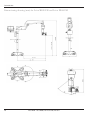
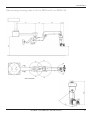
Dimensioning drawing (mm) Leica M844 F40 and
Leica M820 F40
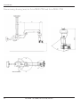
Dimensioning drawing (mm) Leica M844 C40
and Leica M820 C40
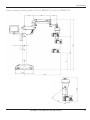
Dimensioning drawing (mm) for Leica M844 CT40
and Leica M820 CT40
Dimensioning drawing (mm) for Leica M844 F19
and Leica M820 F19
48
48
48
48
49
Leica M844 – Leica M820 / Ref. 10 713 294 / Version I
66
66
66
67
67
67
68
69
69
69
70
71
72
73
Introduction
User manual
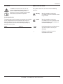
Symbols in this user manual
In addition to instructions for use, this user
manual also provides important safety notes
(see the chapter entitled, "Safety notes").
Read the user manual carefully and thoroughly
before placing the product in operation.
The symbols used in this user manual have the following
meanings:
Warning
Warning regarding use hazard or
noncompliant use that can lead to serious
injury or death.
Caution
Warning regarding use hazard or
noncompliant use that can lead to minor
injury, but significant article, property or
environmental damage.
Product identification
The model code and serial number of your product are provided
on the nameplate found on the underside of the swing arm.
Write this data into your user manual and always refer to it
when you contact us or the service workshop regarding any
questions you may have.
Model:
Serial No.:
Useful information that can help the user
operate the product correctly and
efficiently.
➩
Request for action; here, you are
requested to take action.
Leica M844 – Leica M820 / Ref. 10 713 294 / Version I
3
Introduction
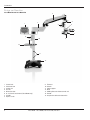
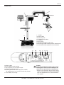
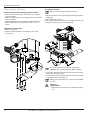
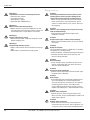
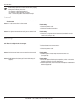
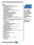
Design and function
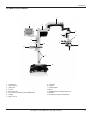
Leica M844 F40 and Leica M820 F40
3
4
2
1
5
9
6
7
13
15
10
8
14
11
12
1
2
3
4
5
6
7
8
4
Control unit
Horizontal arm
Swing arm
XY unit
Binocular tube
0° assistant’s attachment (Leica M844 only)
Handle
Optics carrier
9
10
11
12
13
14
15
Tilt head
Column
Cable support
Base
Holding fixture for video control unit
Handle
Suspension device for footswitch
Leica M844 – Leica M820 / Ref. 10 713 294 / Version I
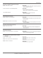
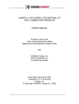
Introduction
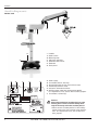
Leica M844 F19 and Leica M820 F19
3
1
2
4
9
5
13
15
6
10
7
14
8
11
12
1
2
3
4
5
6
7
8
Control unit
Horizontal arm
Swing arm
XY unit
Binocular tube
0° assistant’s attachment (Leica M844 only)
Handle
Optics carrier
9
10
11
12
13
14
15
Tilt head
Column
Cable support
Base
Holding fixture for video control unit
Handle
Suspension device for footswitch
Leica M844 – Leica M820 / Ref. 10 713 294 / Version I
5
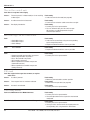
Introduction
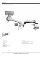
Leica M844 C40 and Leica M820 C40
3
16
4
5
9
6
2
1
7
13
8
17
1
2
3
4
5
6
7
8
6
Control unit
Horizontal arm
Swing arm
XY unit
Binocular tube
0° assistant’s attachment
Handle
Optics carrier
9
13
16
17
Tilt head
Holding fixture for video control unit
C40 ceiling mount
Wall mount for control unit (optional)
Leica M844 – Leica M820 / Ref. 10 713 294 / Version I
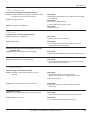
Introduction
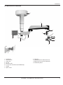
Leica M844 CT40 and Leica M820 CT40
18
3
4
9
5
6
2
1
7
13
8
17
1
2
3
4
5
6
7
8
Control unit
Horizontal arm
Swing arm
XY unit
Binocular tube
0° assistant’s attachment (Leica M844 only)
Handle
Optics carrier
9
13
17
18
Tilt head
Holding fixture for video control unit
Wall mount for control unit (optional)
CT40 ceiling mount
Leica M844 – Leica M820 / Ref. 10 713 294 / Version I
7
Controls
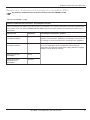
Stands/ceiling mounts
F40 floor stand
21
20
19
24
7
7
19
20
21
22
23
24
23
22
25
31
30
26
27
28
h
29
25
26
27
28
29
30
Power supply
Fuse holder (2x 6.3 A, time-lag)
Running-time meter for the surgical microscope
Potential equalization socket
Socket for remote brake release
Auxiliary power outlet (max. output power 100 VA)
For requirements of use, see the Technical data, page 67.
31 Fuse holder (1 A, time-lag)
Type
10448139
SN
211004003
Made in CH
Leica Microsystems (Schweiz) AG
CH-9435 Heerbrugg
MODEL
8
Handles
Power switch
Balancing knob
Swing arm stop lever
Footbrake release lever
Footbrake
Touch panel
LEICA M844 F40
50/60Hz
100V -230V
400VA
2x T6.3A/250V
~
Caution 1
Connecting unauthorized secondary devices to the
auxiliary power socket can lead to damage to the
surgical microscope and to the secondary device!
➩Never connect secondary devices to the auxiliary
power socket unless they conform to the specifications. For requirements of use, see the Technical
data, page 67.
Leica M844 – Leica M820 / Ref. 10 713 294 / Version I
Controls
F19 floor stand
83
85
20
85
85
84
24
19
7
7
19
20
22
23
24
83
84
85
23
22
27
25
26
27
28
30
Power supply
Fuse holder (2x 6.3 A, time-lag)
Hour meter for the surgical microscope
Potential equalization socket
Auxiliary power outlet (max. output power 100 VA)
For requirements of use, see the Technical data, page 67.
31 Fuse holder (1 A, time-lag)
28
23
Handles
Power switch
Balancing knob
Footbrake release lever
Footbrake
Touch panel
Retaining hook (blocks swing arm)
Retaining pin (holds retaining hook in released state)
Articulation brakes (regulate ease of movement)
30
31
26
25
Caution 1
Connecting unauthorized secondary devices to the
auxiliary power socket can lead to damage to the
surgical microscope and to the secondary device!
➩Never connect secondary devices to the auxiliary
power socket unless they conform to the specifications. For requirements of use, see the Technical
data, page 67.
Leica M844 – Leica M820 / Ref. 10 713 294 / Version I
9
Controls
C40 ceiling mount
Remote control
27
26
28
25
21
20
24
7
19
20
21
24
26
27
28
25
31
30
26
7
27
28
h
29
25
26
27
28
29
30
Power supply
Fuse holder (2x 6.3 A, time-lag)
Hour meter for the surgical microscope
Potential equalization socket
Socket for remote brake release
Auxiliary power outlet (max. output power 100 VA)
For requirements of use, see the Technical data, page 67.
31 Fuse holder (1 A, time-lag)
Type
10448139
SN
211004003
Made in CH
Leica Microsystems (Schweiz) AG
CH-9435 Heerbrugg
MODEL
10
19
Handles
Power switch
Balancing knob
Swing arm stop lever
Touch panel
No function
Up
Down
LEICA M844 C40
50/60Hz
100V -230V
400VA
2x T6.3A/250V
~
Caution 1
Connecting unauthorized secondary devices to the
auxiliary power socket can lead to damage to the
surgical microscope and to the secondary device!
➩Never connect secondary devices to the auxiliary
power socket unless they conform to the specifications. For requirements of use, see the Technical
data, page 67.
Leica M844 – Leica M820 / Ref. 10 713 294 / Version I
Controls
CT40 ceiling mount
Remote control
27
28
21
20
24
7
19
20
21
24
27
28
Handles
Power switch
Balancing knob
Swing arm stop lever
Touch panel
Up
Down
25
31
30
19
26
7
27
28
h
29
Type
10448139
SN
211004003
Made in CH
Leica Microsystems (Schweiz) AG
CH-9435 Heerbrugg
MODEL
LEICA M844 CT40
50/60Hz
100V -230V
400VA
2x T6.3A/250V
~
25
26
27
28
29
30
Power supply
Fuse holder (2x 6.3 A, time-lag)
Hour meter for the surgical microscope
Potential equalization socket
Socket for remote brake release
Auxiliary power outlet (max. output power 100 VA)
For requirements of use, see the Technical data, page 67.
31 Fuse holder (1 A, time-lag)
Caution 1
Connecting unauthorized secondary devices to the
auxiliary power socket can lead to damage to the
surgical microscope and to the secondary device!
➩Never connect secondary devices to the auxiliary
power socket unless they conform to the specifications. For requirements of use, see the Technical
data, page 67.
Leica M844 – Leica M820 / Ref. 10 713 294 / Version I
11
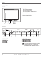
Controls
Control unit
Front view
24 Touch panel
32 Brightness/contrast adjustment
Press once to adjust brightness
Press twice to adjust contrast
Press three times to save adjustment and exit
33 Decrease value
34 Increase value
35 Video mode active LED
36 Video mode/control unit (microscope) mode switch
37 Control unit mode active LED
24
32
33 34
35 36 37
Connections
DVI
SERVICE
LCD
IN/OUT
USB
VIDEO
IN
1
IN/OUT
EXTERN
2
FOOT/HAND
1
2
1
ADF
2
RESET
48
38
38
39
40
41
42
43
39
Service interface
Reset button
USB connection
Video input (BNC)
Internal CAN 1
Internal CAN 2
40
41
42
43
44
44
45
46
47
48
45
46
47
External CAN
Footswitch or handswitch 1
Footswitch or handswitch 2
ADF Additional Function 1
ADF Additional Function 2
ADF 1 and 2 are digital relay outputs that can switch
24 V/2 A. During operation, use only the cables
provided for CAN, video and footswitch in order to
prevent malfunctions.
12
Leica M844 – Leica M820 / Ref. 10 713 294 / Version I
Controls
Leica M844 and Leica M820 surgical microscopes
57
59
58
56
54
7
60
53
52
51
50
63
49
7
49
50
51
52
53
54
Handles
Lamp cover opener
OCF – Optics Carrier Functions
CAN bus
Socket for external supply of slit lamp
OttoFlex/slit lamp switch
Rotary knob for focus fine adjustment (0° assistant’s
attachment for Leica M844 only)
56
57
58
59
60
61
62
63
62
61
Rotary knob for tilt drive (motorized)
Magnification display with XY reverse display
Focus reset
XY reset
Manual zoom emergency drive
Quick-change lamp mount
Slot for filter slide
OttoFlexTM II iris diaphragm
Leica M844 – Leica M820 / Ref. 10 713 294 / Version I
13
Controls
Leica M844 accessories
A comprehensive range of accessories enables the Leica M844 surgical microscope to be matched to the requirements of the task
in hand. Your Leica representative will be pleased to help you select the appropriate accessories.
0° assistant’s attachment
64 Documentation port
65 Rotary ring for adjusting the diaphragm
64
65
Closing the diaphragm can affect the red reflex in
the video image.
66 Clamping screw for locking the binocular tube in place
Optionally, the clamping screw can be replaced
with the provided slotted screw.
66
67 Clamping screw for releasing the quick changer
68 Focus fine adjustment knob
69 Lever for turning the binocular tube by ±15°
67
69
68
Double wing
The Double Wing allows for a third observer in addition to the
surgeon and the assistant.
• the same image detail for each observer
• 50 % light distribution with the assistant, still 100 % light for
the surgeon
• 100 % stereopsis for all observers
• ±15° horizontal rotation of binocular tubes
The M84x Double Wing (10446740) is available as an
optional accessory.
14
Leica M844 – Leica M820 / Ref. 10 713 294 / Version I
Controls
Leica M820 accessories
A comprehensive range of accessories enables the Leica M820 surgical microscope to be matched to the requirements of the task
in hand. Your Leica representative will be pleased to help you select the appropriate accessories.
Beam splitter
Beam splitter, rotatable, 50/50%
Attachment for second observer
1
•
•
•
•
Allows viewing by a second person or documentation
Light distribution: 50% to the side, 50% backwards
The side exit allows a 180° rotation to the left and right
Rotate always completely to the left or right side and tighten
with clamping screw (1)
Leica M844 – Leica M820 / Ref. 10 713 294 / Version I
15
Controls
Leica M844 and Leica M820 accessories
75
65
55
Binocular tube, 180° variable
• tilts 180°
TM
Binocular tube 10° – 50° UltraLow II
• with extra-low viewing height
• adjustable viewing angle and height
• adjustable interpupillary distance
75
65
55
Binocular tube 5° – 25°
• adjustable viewing angle and height
• adjustable interpupillary distance
Binocular tube 10° – 50° with PD
• adjustable viewing angle and height
• adjustable interpupillary distance
Binocular tube, low
• not tiltable
Binocular tube 10° – 50°, low
• adjustable viewing angle and height
• adjustable interpupillary distance
16
Binocular tube 30° – 150°
• tilts 120°
• adjustable interpupillary distance
Leica M844 – Leica M820 / Ref. 10 713 294 / Version I
Controls
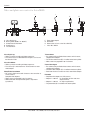
Foot/handswitches and handles
Standard configuration "Cataract"
Here is an overview of all possible footswitches and
handswitches that you can use to control your Leica M820 and
Leica M844 surgical microscopes with the standard
configuration "Cataract".
16-function footswitch, cross
Footswitches, handswitches and handles can be
individually assigned for each user in the configuration
menu (see page 43).
12-function footswitch, cross
Handswitch
12-function footswitch, long
Handles
Leica M844 – Leica M820 / Ref. 10 713 294 / Version I
17
Controls
Standard configuration "Retina"
Here is an overview of all possible footswitches and
handswitches that you can use to control your Leica M820 and
Leica M844 surgical microscopes with the standard
configuration "Retina".
16-function footswitch, cross
Footswitches, handswitches and handles can be
individually assigned for each user in the configuration
menu (see page 43).
12-function footswitch, cross
Handswitch
12-function footswitch, long
Handles
18
Leica M844 – Leica M820 / Ref. 10 713 294 / Version I
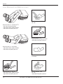
Controls
Video and photo accessories for Leica M844
I
I
H
D
B
A
A
B
C
D
E
C
Leica 2D pick-up
0° assistant’s attachment
Photo/TV dual attachment
Photocamera
TV attachment
E
D
F
G
H
I
Leica 2D pick-up
• Video system for recording 2D video sequences.
• The camera (A) is installed between the assistant’s
attachment and the binocular tube.
Leica 2D C-Mount
• Video system for recording 2D video sequences.
• The camera (I) is mounted on the TV attachment or zoom
video adapter.
Photo/TV dual attachment
• For using a video camera with C-mount at the same time as
an SLR camera.
Complete with adapters.
• Video camera engageable in 45° increments.
• Video outlet with incorporated brightness adjustment
(3 positions).
F
G
Zoom video adapter
Phototube
Video camera (such as the Leica D2D V3)
Leica 2D C-Mount
TV attachment
• For commercially-available video cameras with C-mount,
complete with adapter.
• The TV tube attachment (E) is installed at the video port
of the 0° assistant’s attachment.
• Video camera can be latched in 90° increments.
Zoom video adapter
• For commercially-available video cameras with C-mount,
complete with adapter.
• The zoom video adapter (F) is installed at the video port
of the 0° assistant’s attachment.
• Zoom and fine focus function for Leica zoom video adapter
Phototube
• Complete with adapter, for SLR cameras.
• Adapter f = 250 mm: for large fields of view and short
exposure times.
• Adapter f = 350 mm: for high magnifications.
• The phototube (G) is installed at the video port
of the 0° assistant’s attachment.
Leica M844 – Leica M820 / Ref. 10 713 294 / Version I
19
Controls
Video and photo accessories for Leica M820
I
I
H
A
A
B
C
D
E
B
C
Leica 2D pick-up
Beam splitter (50/50 % or 70/30 %)
Photo/TV dual attachment
Photocamera
TV attachment
F
G
H
I
Leica 2D pick-up
• Video system for recording 2D video sequences.
• The camera (A) is installed between the optics carrier and
the binocular tube.
Leica 2D C-Mount
• Video system for recording 2D video sequences.
• The camera (I) is mounted on the TV attachment or zoom
video adapter.
Photo/TV dual attachment
• For using a video camera with C-mount at the same time as
an SLR camera.
Complete with adapters.
• Video camera engageable in 45° increments.
• Video outlet with incorporated brightness adjustment
(3 positions).
20
E
D
D
F
G
Zoom video adapter
Phototube
Video camera (such as the Leica D2D V3)
Leica 2D C-Mount
TV attachment
• For commercially-available video cameras with C-mount,
complete with adapter.
• The TV tube attachment (E) is installed at the beam splitter.
• Video camera engageable in 90° increments.
Zoom video adapter
• For commercially-available video cameras with C-mount,
complete with adapter.
• The zoom video adapter (F) is installed at the beam splitter.
• Zoom and fine focus function for Leica zoom video adapter
Phototube
• Complete with adapter, for SLR cameras.
• Adapter f = 250 mm: for large fields of view and short
exposure times.
• Adapter f = 350 mm: for high magnifications.
• The phototube (G) is installed at the beam splitter.
Leica M844 – Leica M820 / Ref. 10 713 294 / Version I
Preparation for operation
Checklist: Before the operation
Cleaning the optical accessories
➩Select the eyepieces, objective and the documentation
accessories (if used) and check them for cleanliness.
➩Remove dust and dirt (see page 58).
Checking accessories
➩Lock the swing arm.
➩Outfit the microscope with all accessories for use
(see pages 22-24).
➩Turn 0°-assistant’s attachment to the desired side
(Leica M844, see page 25) or install attachment for second
observer on the desired side (Leica M820).
Balancing
➩Release and balance swing arm
(see pages 33 and 34).
Function check
➩Switch the microscope on.
Warning 1
Motors return to their home positions
➩Before switching on the microscope, ensure that the
travel paths of the X- and Y-axes and the focus motor
are free of obstructions.
➩Check the Main Light 1, Main Light 2 and OttoFlexTM II
illuminators. Replace defective bulbs before the
operation begins.
➩Test all handswitch and footswitch functions.
➩Check the brake function using both the handles and
the remote brake release (see page 33).
Positioning at the OP table
➩Position the surgical microscope at the operating table as
desired and secure the brakes on the floor stand.
(see page 36).
Checking tube settings
➩Check the tube and eyepiece setting for the selected user
(see page 24).
➩Treat the eyepieces with an antifogging compound if
necessary.
Sterility
➩Fit sterile components and sterile drape if used
(see page 59).
Warning 2
Danger of fatal electric shock
➩Operate the system only with all equipment in its
proper position (all covers fitted, doors closed).
Leica M844 – Leica M820 / Ref. 10 713 294 / Version I
21
Preparation for operation
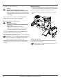
Fitting optical accessories for Leica M844
Warning 3
Risk of injury from downward movement of surgical
microscope!
➩Complete all preparations and adjustments to the
stand before the operation.
➩Never balance or re-equip the instrument over the
field of operation.
➩Before re-equipping, always lock the swing arm.
➩After re-equipping, always rebalance the microscope
on the swing arm.
➩Do not release the brakes when the instrument is in an
unbalanced state.
➩Before re-equipping during the operation, first swing
the microscope away from the operating field.
Take care that the articulation brakes are tightened
and the swing arm is blocked before you mount
accessories to your Leica M844 (see page 34).
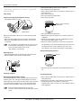
Fitting objectives
➩Screw the objectives onto the microscope (right-hand
threading).
Fitting the 0° assistant’s attachment
Fitting the tube
➩Release the clamping screw on the dovetail ring of the 0°
assistant’s attachment and remove the black protective cover.
➩Carefully insert the second observer tube and tighten the
clamping screw.
Fitting eyepieces
➩Fasten the eyepieces with the fixing rings in the tubes.
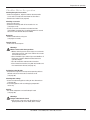
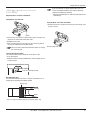
Fitting the Double Wing
We recommend mounting the longer arm of the Double
Wing on the side of the focus housing in order to
achieve optimal ergonomic conditions.
➩Screw out the clamping screw
until it stops by means of the
screwdriver.
➩Insert the attachment of the
Double Wing into the dovetail
ring so that the arrow is
positioned exactly over the
clamping screw.
➩Hold the Double Wing firmly and tighten the clamping screw.
The 0° assistant’s attachment must be directly
When the combination with the Double Wing is used
we recommend that the main surgeon uses the
UltraLowTM II binocular tube. The UltraLowTM II
binocular tube offers better ergonomic conditions.
Clamping screw
attached to the optics carrier.
➩Unscrew the clamping screw as far as necessary using a
screwdriver.
➩Insert the 0° assistant’s attachment into the dovetail ring.
➩While holding the 0° assistant’s attachment in place, tighten
the clamping screw.
Do not use a beam splitter in addition to the
0° assistant’s attachment.
22
Leica M844 – Leica M820 / Ref. 10 713 294 / Version I
Preparation for operation
Warning 3
Risk of injury from downward movement of surgical
microscope!
➩Complete all preparations and adjustments to the
stand before the operation.
➩Never balance or re-equip the instrument over the
field of operation.
➩Before re-equipping, always lock the swing arm.
➩After re-equipping, always rebalance the microscope
on the swing arm.
➩Do not release the brakes when the instrument is in an
unbalanced state.
➩Before re-equipping during the operation, first swing
the microscope away from the operating field.
Take care that the articulation brakes are tightened
and the swing arm is blocked before you mount
accessories to your Leica M820 F19 (see page 34).
Fitting objectives
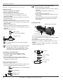
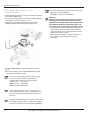
Fitting the attachment for second observer
Tube
➔
Fitting optical accessories for Leica M820
Knurled ring
1
➩Install the attachment for second observer to the beam
splitter.
➩Align the attachment for second observer as required.
➩Fit the tube and set up the image with the knurled ring.
Fitting the tube
➩Release the clamping screw on the beam splitter and
attachment for second observer and remove the protective
cover.
➩Carefully insert the tube and tighten the clamping screw.
Fitting eyepieces
➩Affix the eyepieces with the fixing rings in the tubes.
Mounting beam splitter, rotatable
➩Screw the objectives onto the microscope
(right-hand threading).
Fitting the beam splitter
1
1
➩Unscrew the clamping screw to the stop.
➩Insert the beam splitter into the dovetail ring and turn slightly
to the side until the positioning screw engages the guide.
• Remove the clamping screw (1)
• Mount the grub screw (1)
• Place beam splitter, rotatable into the
dovetail ring from above
• Tighten the grub screw (1)
Leica M844 – Leica M820 / Ref. 10 713 294 / Version I
23
Preparation for operation
Adjusting optical accessories – general
information
Tube settings
Acquiring and adjusting interpupillary distance
➩Set individual diopter values for each eyepiece.
➩Set to the minimum magnification.
➩Place a flat test object with sharp contours under the lens at
working distance.
➩Focus the microscope.
➩Set to the maximum magnification.
➩Focus the microscope.
Interpupillary distance scale
Rotary ring for adjusting
the diopters
75
65
55
Setting wheel
Adjust the interpupillary distance to a value between 55 mm
and 75 mm.
➩Adjust the interpupillary distance using the setting wheel.
➩Adjust the interpupillary distance until you see a circular
image field.
This procedure must be done once for each user. The
acquired value (see display) can be stored for each
user in the "User Settings" menu under
"Tube Settings" (see page 44).
➩Set to the minimum magnification.
➩Without looking into the eyepieces, turn both eye lenses to
+5 diopters.
➩Slowly turn the eyepieces towards -5 individually for each
eye until the test object appears sharp.
➩Select the highest magnification and check the sharpness.
This procedure has to be performed only once for each user.
The acquired values can be stored for each user in the
"User Settings" menu under "Tube Settings" (see page 44).
Adjusting the pupillary distance
Adjusting the tilt
➩Hold the eyepiece tubes of the binocular with both hands.
➩Tilt the eyepiece tubes upwards or downwards.
Eyecup
➩Rotate the eyecups up or down until the desired distance is
set.
Setting up eyepieces
Checking parfocality
Determining/adjusting diopter settings
The individual diopters can be adjusted continuously for each
eyepiece from +5 to -5. Only this method will ensure that the
image will stay in focus within the entire zoom range = parfocal.
The treatment microscope ensures a high degree of fatigue
resistance when the dioptre setting is correct for both eyes.
➩Place a flat test object with sharp contours under the lens at
working distance.
➩Zoom through the whole range, observing the test object.
➩The image sharpness must remain constant at all
magnifications. If this is not the case, check diopter settings
of the eyepieces.
A parfocal adjusted microscope ensures that
assistant´s view and monitor image will always remain
sharp
24
Leica M844 – Leica M820 / Ref. 10 713 294 / Version I
Preparation for operation
Adjusting optical accessories for
Leica M844
Adjusting the 0° assistant’s attachment
If you are working at a large magnification, you can
increase the depth of field of your video or photo by
reducing the diaphragm opening.
➩Closing the diaphragm can affect the red reflex in the
video image.
Changing the assistant side
Focusing the 0° assistant’s attachment
2.
➩Rotate the fine focus button to precisely focus the image seen
by the assistant.
1.
Screw
➩Loosen the screw, lift the surgeon tube on quick changer and
rotate the assistant tube to the other side.
➩Retighten the screw.
➩After changing the assistant side, turn the camera by 180° to
correct the orientation of the video image.
No accessories need to be removed in order to change
the assistant side.
Fine focusing knob
Level-up the eyepiece tubes
The assistant tube can be rotated 15° to the left or right.
➩Push lever down.
➩Rotate the tube in the desired direction until it engages at one
of the markings.
Lever for rotating the tube
Documentation port
The documentation port of the 0° assistant’s attachment has a
diaphragm for optimizing the depth of field.
Rotary ring
Closed
Open
➩You can adjust the diaphragm by turning the rotary ring.
Leica M844 – Leica M820 / Ref. 10 713 294 / Version I
25
Preparation for operation
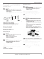
Fitting documentation accessories
Fitting the Leica 2D
➩See Leica 2D User Manual (10708979).
Fitting the photo/TV dual attachment
➩Fit dual attachment on the assistant side of the
0°-assistant’s attachment (Leica M844) or on the beam
splitter (Leica M820).
➩Equip the video camera with the TV objective and insert into
the dual attachment.
➩Tighten the clamping screw.
➩Equip the photo camera with the camera adapter. Screw the
photo objective to the camera adapter. Fit the camera to the
dual attachment.
➩Tighten the clamping screw.
➩Loosen the clamping screw and engage the video camera
until it latches in one of the 45° steps depending on the available space.
➩Tighten the clamping screw.
Adjust parfocality of the zoom video adapter.
➩Select the highest magnification.
➩Place a flat test object with sharp contours under the
objective.
➩Look through the eyepieces and focus the
microscope.
➩Select the lowest magnification.
➩Set the maximum magnification (f=100) on the zoom
video adapter.
➩Focus the monitor image on the zoom video adapter.
➩Set the desired image magnification at the zoom
video adapter.
Fitting the phototube
Adjusting the magnification
Video camera
(such as the Leica D2D V3)
Focusing knob
Clamping screw
The object image at the camera output is laterally
reversed!
➩Fasten the phototube to the video port of the
0°-assistant’s attachment (Leica M844) or to the beam splitter
(Leica M820).
➩Secure the camera adapter to the SLR camera.
➩Connect the f = 250 mm or f = 350 mm adapter to the camera
adapter.
➩Secure the camera, complete with adapter, in the phototube.
Tighten the clamping screw.
Using the dial, the brightness of the video can be adjusted to 30%, 50% or 100%. One of these filters can be
switched with the 8% filter provided. To do so, remove
the camera and change the filter in the TV output.
Camera
TV attachment / zoom video adapter
➩Fasten the TV attachment to the video port of the
0° assistant’s attachment (Leica M844) or the beam
splitter (Leica M820).
➩Screw the adapter to the camera using the C-mount.
➩Insert the camera with the adapter into the TV attachment
and tighten the clamping screw.
90° click-stop (TV attachment only):
➩Loosen the clamping screw.
➩Latch the camera at one of the 90° steps in accordance with
the space available and tighten the clamping screw.
Video camera (such as the Leica D2D V3)
C-mount adapter
Clamping screw
TV attachment
26
Leica M844 – Leica M820 / Ref. 10 713 294 / Version I
Camera adapter
Adapter
Clamping screw
Phototube
Preparation for operation
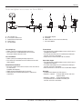
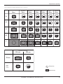
Selecting documentation accessories
Zoom video adapter
TV
attachment
PhotoTV dual
attachment
35mm
55mm
60mm
TV
attachment
70mm
PhotoTV dual
attachment
Zoom video
Adapter
TV
attachment
85mm
100mm
107mm
1/4 “
1/3 “
1/2 “
2/3 “
1“
Photo/TV dual attachment
250 mm
350 mm
35 mm
Digital
Photo
Camera
Field of view
Monitor/image
Leica M844 – Leica M820 / Ref. 10 713 294 / Version I
27
Preparation for operation
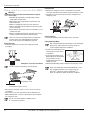
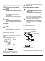
Fastening the slit lamp
Mounting the slit lamp
General safety information when handling the slit lamp
• When installing and using the slit lamp, make sure not to
pinch any cables.
• When installing, make sure that the interlock of the slit lamp
latches securely.
• Only qualified personnel is allowed to handle the slit lamp.
• When handling the slit lamp take care not to crush any
fingers.
Make sure that the interlock latches securely.
➩Loosen the clamp screw (1) and slide the slit lamp (5) into the
guiding (6).
➩Fasten the clamp screw (1).
Power supply and control signals are connected to the slit lamp
via the quick release fastener in the guiding (6).
Mounting the extension plate
➩Lock the swing arm.
➩Fasten the extension plate (2) to the optics carrier with
4 screws (3).
4
6
5
1
The slit lamp may only be used with an objective
(10445937) with a working distance (WD) of 200 mm.
2
➩Insert the 3-pin plug of the dual cable into the external supply
socket (4) on the optics carrier.
➩Insert the 5-pin plug of the dual cable into the OCF socket (50)
on the optics carrier (see page 13).
Make sure that there always is a spare lamp with 50 W
on-hand.
3
28
Warning 4
Danger of burns
➩The lamp housing and cover may become hot during
use.
Leica M844 – Leica M820 / Ref. 10 713 294 / Version I
Preparation for operation
Adjusting the slit lamp
➩Move the slit lamp into middle position using the footswitch.
Assign the functions OCF2 pulse and OCF3 pulse on the
hand switch or foot switch used so that the slit lamp
can be moved to the right (OCF3) or left (OCF2) using
these two keys.
➩Rotate the prism into middle position.
➩Rotate the prism into both end positions and adjust the
magnification so that the slit remains in the image field to the
left and right.
➩Make sure that there is no obvious difference between the
prism end positions for lateral adjustment referring to the slit
image and the edge of the diaphragm.
Emergency operation
If the motor of the prism is inoperative, the prism may be moved
by hand.
Dismounting the slit lamp
When dismounting the slit lamp, make sure that both
stoppers are in the bottom position.
End position I
Prism into
End position II
middle position
Left-hand and right-hand of the arc there are two lockable stoppers (1) which may be adjusted individually by
the doctor. When a stopper is reached, it may be
circumnavigated by pressing the hand switch or foot
switch again.
1
Leica M844 – Leica M820 / Ref. 10 713 294 / Version I
29
Adjusting the slit lamp
Caution 2
Danger of crushing due to moving parts!
The parts of the slit lamp that are moved by motors
may crush fingers or the hand when used improperly.
➩When handling the slit lamp, take care not to crush
any fingers.
Moving the slit lamp
➩Assign the functions OCF2 pulse and OCF3 pulse on the hand
switch or foot switch used so that the slit lamp can be moved
to the right (OCF3) or left (OCF2) using these two keys.
or
➩Move the slit lamp to the right or left with the nurse switch
(1).
➩For activation of the slit lamp, use the Slitlamp/OttoFlex
switch (53) on the optics carrier (see page 13).
Adjusting the brightness of the slit lamp
Warning 5
Danger of eye injuries!
The light source of the slit lamp might be too bright
for the patient.
➩Dim the slit lamp before switching it on.
➩Slowly increase the brightness until the image is
illuminated optimally for the operating doctor.
➩To switch the slit lamp on or off, use the OttoFlex ON/OFF
function on the hand switch or foot switch.
➩To adjust brightness, press the „+“ or „–“ -button, or directly
press the brightness bar of the slit lamp.
Clicking the „+“ or „–“ -button changes the brightness
value in increments of 1. Holding the mouse button
down changes the value in increments of 5.
➩Brightness of the slit lamp may also be changed by using a
connected hand switch or foot switch with the OttoFlex +/–
function.
30
1
2
Adjusting the slit width
The width of the slit can be adjusted with the lever (2) on the
lamp housing of the slit lamp.
The slit width can be adjusted between 0.01 bis 14 mm.
The slit height is 14 mm.
Leica M844 – Leica M820 / Ref. 10 713 294 / Version I
Connecting the BIOM to the slit lamp
1
Phototoxic damage to the retina during eye surgery
Warning 6
Damage to the eyes due to prolonged exposure!
The light of the instrument may be harmful. Risk of eye
damage increases with the duration of exposure.
➩Do not exceed the exposure limits.
An exposure to this instrument for longer than 2.8 min
at maximum output power exceeds the exposure
limits.
2
The following table shows the allowed surgery durations and
their possible extension when reducing the slit width:
➩Insert the plug of the BIOM into the socket (2) on the slit lamp.
➩Use the rotary switch (1) to change between BIOM and slit
lamp.
Sterile covers for the slit tube
The slit tube of the slit lamp can be protected by sterile cover
(3), the lever for adjusting the slit width can be protected by
sterile cover (4).
3
4
slit width [mm]
>6
5
4
3
2
1
time [s]
164
181
233
270
455
909
➩Protect the patient by:
• short illumination times
• low brightness level
• switching the light off when interrupting the surgery
It is recommended to adjust the brightness to the minimum necessary for the surgery.
Babies or aphacia patients, where the eye lens has not been
exchanged by an artificial lens with UV-protection, infants and
patients with eye sickness are at a greater risk.
There also is a greater risk, if the patient was exposed to the
same or any other ophthamological instrument using a bright
visible light source within the previous 24 hours.
This applies especially, if the eye was examined by retina
photography.
Decisions about brightness must be made case by case.
In any case the surgeon has to make a risk-benefit analysis
concerning the applicable brightness.
Despite any effort to minimize the risk of damage to the retina
by the surgical microscope, injuries still might occur.
Photochemical damage to the retina is one possible
complication due to the necessity of using bright light to visualize eye structures during difficult ophthamologic processes.
Leica M844 – Leica M820 / Ref. 10 713 294 / Version I
31
Preparation for operation
Wide-angle observation system
(such as Oculus)
➩Fit the SDI between the 0° assistant’s attachment and tube as
pictured (Leica M844 only).
➩Insert the seven-pin plug of the SDI control cable (10448163)
into the OCF socket on the optics carrier.
➩Insert the five-pin plug of the SDI power supply cable
(10448162) into the CAN socket on the optics carrier.
For further information, please see the manufacturer’s
operating instructions OCULUS
(SDI/BIOM = Trade names of OCULUS).
Warning 5
There is a danger of injury to the patient as a result of
changing the working distance using the motorized
adjustment of the ceiling mount if the working distance
falls below the minimum of 140 mm due to the use of
accessories (such as wide-angle observation systems).
➩The footswitch function for moving the ceiling mount
up and down may not be used in combination with
accessories that cause the working distance to fall
below the minimum of 140 mm.
➩Before up/down movements, always check first to
ensure that the range of movement is free of
obstructions.
➩Screw the BIOM adapter into the underside of the optics
carrier.
➩Loosen the clamping screw, slide the BIOM into the guide
and retighten the clamping screw.
You can control the wide-angle observation system
using your Leica handswitch or footswitch by
assigning the functions OCF1, OCF2 and OCF3:
Inverter on/off
OCF1 pulse
BIOM focus up
OCF2 pulse
BIOM focus down OCF3 pulse
If you select the function "OCF1 + XY reverse", the
wide-angle observation system is switched on and, at
the same time, the X and Y movement directions are
reversed.
The SDI is mounted directly on the optics carrier of the
Leica M820. If a beam splitter is to be used in addition,
mount it on the SDI using a stereo adapter (10446992).
32
Leica M844 – Leica M820 / Ref. 10 713 294 / Version I
Preparation for operation
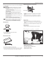
Preparing the stand (F40,C40,CT40)
Balancing the swing arm
Warning 6
Risk of injury through surgical microscope moving
down!
➩Never balance or re-equip the instrument over the
field of operation.
➩After re-equipping, always rebalance the microscope
on the swing arm.
Releasing the swing arm
Caution 2
There is a risk of damage to the surgical microscope
from uncontrolled tilting!
➩Firmly hold the handles before triggering the
"All Brakes" function.
➩Grip and turn one handle to release the brakes.
➩At the same time, pull the stop lever and bring it into a
horizontal position. The swing arm is now released.
If necessary, rebalance the swing arm.
Releasing the brakes
Stop lever
Rotary knob
➩Release the swing arm (see below).
➩Hold the microscope by the handles.
➩Turn one handle to release the brakes (All Brakes).
➩Check whether the microscope drifts up or down.
Microscope drifts downwards:
➩Turn rotary knob clockwise.
Warning 8
Risk of injury through surgical microscope moving
down!
➩Complete all preparations and adjustments to the
stand before the operation.
➩If settings need to be altered during the operation,
first swing the microscope away from the operating
field.
➩If the microscope needs to be re-equipped, do this
before the operation.
➩Before re-equipping, always lock the swing arm.
➩Do not use the handle or remote brake release when
the instrument is in an unbalanced state.
Microscope drifts upwards:
➩Turn rotary knob counterclockwise.
Locking the swing arm
Forwards
Warning 7
Risk of injury through surgical microscope moving
down!
➩Always lock the swing arm:
when transporting the microscope
when changing equipment
Caution 2
There is a risk of damage to the surgical microscope
from uncontrolled tilting!
➩Firmly hold the handles before triggering the
"All Brakes" function.
➩Pull the stop lever and bring it into a vertical position.
➩Hold and turn one or both handles to release the brakes
(All Brakes).
➩Move the swing arm up and down until the transport lock
engages.
➩The swing arm is now locked.
Backwards
Unless they are individually configured for the current
user, the brakes are released by turning the handles as
follows:
➩Turn backwards and hold: selected brakes are released
➩Turn forwards and hold: all brakes are released
The handles can be individually assigned up to
4 functions for each user in the "User Settings" menu.
The "All Brakes" function must be selected at least
once (see page 44).
Leica M844 – Leica M820 / Ref. 10 713 294 / Version I
33
Preparation for operation
The brakes can also be released using a remote brake
release.
Preparing the stand (F19)
Balancing the swing arm
REM
OT
REL E BRA
EAS KE
E
Warning 6
Risk of injury through surgical microscope moving
down!
➩Never balance or re-equip the instrument over the
field of operation.
➩After re-equipping, always rebalance the
microscope on the swing arm.
➩Press and hold the remote brake release button.
➩All brakes on the stand are now released.
Raising and lowering the C40 ceiling mount
The C40 ceiling mount can be raised and lowered electrically.
These functions can be controlled via the remote control unit.
➩"Up" key: raise stand.
➩"Down" key: lower stand.
➩Hold the microscope firmly.
➩Releasing the swing arm
➩See whether or not the microscope drifts.
Microscope drifts downwards:
➩Turn rotary knob clockwise.
Microscope drifts upwards:
➩Turn rotary knob counterclockwise.
Ceiling mount
Up
Down
C40 remote
control
Retaining hook
Brake knob
Brake knob
Rotary knob
Retaining pin
Raising and lowering the CT40 ceiling mount
The CT40 ceiling mount can be lifted and sinked electrically.
These functions can be controlled via buttons on the remote
control unit.
Move telescopic arm to the desired height:
➩"Up" key: lift telescopic arm.
➩"Down" key: sink telescopic arm.
Up
Down
Under permanent-load conditions, the telescope may
not be operated for more than 1 minute in a 10 minute
period. After 2 minutes of uninterrupted operation,
the built-in temperature switch deactivates the motor
of the Leica CT40 ceiling mount.
Adjust the articulation brakes
All joints on the microscope and stand are equipped with articulation brakes, with resistance that adjusts to make the joint
easier or more difficult to move.
Make the joint easier to move:
➩Loosen the black brake knob.
Make the joint more difficult to move:
➩Tighten the black brake knob.
Locking the swing arm
Warning 7
Risk of injury through surgical microscope moving
down!
➩ Always lock the swing arm:
when transporting the microscope
when changing equipment
➩Position the swing arm approximately horizontally.
➩Pull out the retaining pin.
➩Move the swing arm slightly up and down until the
retaining hook engages. The swing arm is now locked.
Releasing the swing arm
➩Move the swing arm slightly up and down, at the same time
pushing the counterlever of the safety hook upwards, until
the retaining pin clicks into position.
➩If necessary, rebalance the swing arm.
34
Leica M844 – Leica M820 / Ref. 10 713 294 / Version I
Preparation for operation
Transport, transporting and parked
positions
Transport of the Leica M844 F40 and Leica M820 F40
Ensure that the display of the control unit does not collide with the XY unit!
Transport of the Leica M844 F19 and Leica M820 F19
Warning 9
Beware of:
• Uncontrolled lateral movement of the swing arm!
• Tilting of the stand!
• Feet in lightweight shoes could become trapped
beneath the casing of the base.
➩Before transport, always set the Leica M820 F40 and
Leica M844 F40 surgical microscopes to the
transport position.
➩Never move the stand in the extended condition.
➩Always push the instrument to displace it; never pull it.
➩Never roll over cables lying on the floor.
Warning 9
Beware of:
• Uncontrolled lateral movement of the swing arm!
• Tilting of the stand!
• Feet in lightweight shoes could become trapped
beneath the casing of the base.
➩Before transport, always set the Leica M820 F19 and
Leica M844 F19 surgical microscopes to the
transport position.
➩Never move the stand in the extended condition.
➩Always push the instrument to displace it; never pull it.
➩Never roll over cables lying on the floor.
Caution 3
Surgical microscope can move without warning!
➩Always lock the footbrake when you are not moving
the system.
Caution 3
Surgical microscope can move without warning!
➩Always lock the footbrake when you are not moving
the system.
Transport position
Whenever you transport your Leica M820 F40 and Leica M844
F40, first bring it into transport position.
Caution 2
There is a risk of damage to the Leica M820 F40 and
Leica M844 F40 surgical microscopes from
uncontrolled tilting!
➩Firmly grasp the handles before triggering the
"All Brakes" function.
Transport position
Whenever you transport your Leica M820 F19 and Leica M844
F19, first bring it into transport position.
➩Unplug and secure the power cable.
➩Pull the retaining pin and engage the retaining hook.
➩Release the articulation brakes.
➩Bring swing arm into transport position.
Articulation brakes
➩Unplug and secure the power cable.
➩Pull the stop lever and bring it into a vertical position.
➩Grasp and turn one or both handles to release the brakes
(All Brakes).
➩Move the swing arm up and down until the transport lock
engages.
➩Bring swing arm into transport position.
Retaining hook
Stop lever
Handle
Handle
Footbrake and release lever
➩Release the handle.
➩Turn the control unit towards the swing arm.
➩Hang the footswitch on the suspension device.
➩Step on the footbrake release lever to release the footbrakes.
➩Move the Leica M820 F40 and Leica M844 F40 by the handle.
➩Tighten the articulation brakes.
➩Turn the control unit towards the XY unit.
➩Place footswitch in the carrier.
➩Release the foot brakes by depressing the foot lever.
➩Move the Leica M820 F19 and Leica M844 F19 by the handle.
Leica M844 – Leica M820 / Ref. 10 713 294 / Version I
35
Preparation for operation
Parked position
Positioning at the operating table
Bring the microscope into rest position after use.
F40 and F19 floor stands
➩After bringing the microscope into transport position, push it
to its storage location.
➩Firmly depress the footbrake.
➩Protect your Leica M820 and Leica M844 by covering it with
its dust cover.
Leica M820 F40, Leica M844 F40, Leica M820 F19 and Leica
M844 F19
➩Bring the Leica M820 F40, Leica M844 F40,
Leica M820 F19 and Leica M844 F19 surgical microscope into
transport position (see page 32).
➩Release the footbrakes (see page 35).
➩Using the handle, carefully push the surgical microscope to
the operating table and position it as desired:
C40 ceiling mount
Positioning options:
Caution 4
Danger of collision!
The surgical microscope can collide with surrounding
components, the ceiling or lamps.
➩Check the danger area before moving the swing
arm.
➩Carefully move the ceiling mount upwards, and
observe ceiling and lamps.
➩Swing the microscope aside.
➩Remove sterile components.
➩Adjust the swing arm parallel to the ceiling mount arm and
lock it.
➩Switch off the power switch on the swing arm.
➩Raise the ceiling mount using the remote control.
CT40 ceiling mount
Caution 4
Danger of collision!
The surgical microscope can collide with surrounding
components, the ceiling or lamps.
➩Check the danger area before moving the swing
arm.
➩Carefully move the ceiling mount upwards, and
observe ceiling and lamps.
All positions are also possible as the mirror image position.
The instrument must be positioned such that the range
of movement is large enough for the expected tasks.
➩Set footbrake.
➩Plug the footswitch into the control unit and position it.
➩Plug the power cable into the horizontal arm.
➩Connect the potential equalization to the horizontal arm.
Warning 9
Danger of fatal electric shock
➩The surgical microscope may be connected to a
grounded socket only.
➩Swing the microscope aside.
➩Remove sterile components.
➩Lock the swing arm.
➩Switch off the power switch on the swing arm.
➩Press the "Up" key on the remote control and raise the stand.
36
Leica M844 – Leica M820 / Ref. 10 713 294 / Version I
Preparation for operation
Sterile drape for stand
Sterile controls
The controls indicated in the diagram can be provided with
steam-sterilizable handles or covers.
Use the sterilizable handles also when you use sterile
disposable drapes; the controls will be easier to grasp.
56
70
60
63
54
7
7
54
56
60
63
70
Handles
Rotary knob for focus fine adjustment
Rotary knob for tilt head
Manual zoom emergency drive
OttoFlexTM II iris diaphragm
Interpupillary distance setting wheel
Also refer to the "Sterilization" table on page 61.
Caution 5
Risk of infection!
➩Leave sufficient space around the stand to ensure
that the sterile drape does not come into contact
with non-sterile components.
You can also use an optional sterile disposable drape.
➩Release the "All Brakes" functions (not available with Leica
M820 F19 and M844 F19) using the handle and extend the
swing arm.
➩Put on sterile gloves.
➩Attach all the sterile controls.
➩Carefully unpack the sterile drape and pull it over the Leica
M820 and Leica M844 surgical microscopes up to the swing
arm.
➩Clamp the protective glass (optional) onto the objective.
➩Do not attach the sterile drape too tightly with the provided
ribbons. It must still be easy to operate the instrument.
Check the ease of movement of the instrument.
Follow the instructions provided by the manufacturer of
the sterile drape.
Ensure that you pull the disposable drape only to the
end of the swing arm and fasten it there! Do not cover
the horizontal arm.
Before the operation
➩Press the sterile controls into position so that they engage.
The rotary knobs 54, 56, 60, 63 and 70 are identical.
Packaging the footswitch in a plastic bag protects it
against dirt.
Leica M844 – Leica M820 / Ref. 10 713 294 / Version I
37
Use
"Reset Buttons"
Positioning the microscope
Joystick für
XY-Bewegung
59
56
7
7 Handles
56 Rotary knob for tilt head
59 XY reset
Coarse positioning
➩Hold the microscope by both handles.
➩Turn one handle to release the brakes (All Brakes) (not
available with Leica M820 F19 and M844 F19).
➩Position the microscope and release the handle.
The brakes can also be released using the remote brake
release (see page 34).
Also refer to the "Release brakes" chapter on page 33.
➩If a drive is in reset position, the reset button assigned to it
appears in green.
➩A "Reset" button that flashes green indicates that the
corresponding drive is moving to reset position.
➩A "Reset" button that appears in gray indicates that the
corresponding drive is outside of the reset position.
Drive settings
Pressing the "Reset All" button returns all motors to
home position and reloads the user settings of the
current user.
Warning 11
Risk of injury from downward movement of
surgical microscope!
➩Do not use the handle or remote brake release when
the instrument is in an unbalanced state.
For Leica M820 F19 and M844 F19 regulate the
articulation brakes according to personal requirements
and accessory weight (see page 34).
Fine positioning
➩Use joystick on footswitch to operate X/Y-drive and position
the microscope.
Return to middle position by pressing the "Reset" key (59)
or the "Reset" buttons on the control unit.
You can assign the function "XY Reverse" on your
handswitch or footswitch in order to reverse the X and Y
movement directions.
You can adjust the speed at which each of the drives is
moved on the "Speed" menu screen.
Adjusting the tilt
➩Turn the rotary knob (56) for tilt adjustment in the desired
direction and hold it there.
➩The microscope tilts in the desired direction.
You can change the drive speeds by clicking the "+"
and "-" buttons. You can also set the speed by directly
clicking the display bars.
The microscope can be tilted 15° forwards and 50°
backwards.
These values can be saved individually for each user
(see page 39).
Pressing the "Reset" button on the control unit returns
the microscope to home position (0°).
38
Leica M844 – Leica M820 / Ref. 10 713 294 / Version I
Use
Clicking the "+" or "-" key changes the brightness value in
increments of one. Holding down the mouse button with
your finger changes the value in increments of five.
Adjusting the microscope
Adjusting the illumination
Warning 12
Light which is too intensive can damage the retina.
➩Safeguard your patients:
short exposure times,
low brightness setting,
use protective filters (GG420 built in).
We recommend setting the minimal required light intensity for the
operation. Infants, small children, aphakic patients who have not
had their lenses replaced by artificial lenses with UV protection,
and persons with eye diseases are at higher risk. The risk is also
elevated if the person to be treated has been exposed to illumination from the same or a similar ophthalmological instrument with
an intense visible light source within the previous 24 hours. This
applies especially to patients that have been examined via retinal
photography.
The decision with regard to the light intensity to be used must be
made on a case-by-case basis. In any event, the surgeon must
evaluate the risks and benefits of the used light intensity.
Damage may occur despite all efforts to minimize the risk of
retinal injury by surgical microscopes. Photochemical retina
damage is a possible complication arising from the necessity to
use intense light to make eye structures visible during difficult
ophthalmological processes.
Adjusting the brightness
You can adjust the brightness of the active Main Light and the
OttoFlexTM II lamp using either the touch panel or the footswitch.
Using the footswitch:
Depending on the functions assigned to the footswitch
(see page 16), you can switch the Main Light and OttoFlexTM II
lamp on and off, and increase and decrease their brightness,
using the foot/handswitch.
Using the touch panel:
You can change the brightness for the active Main
Light and OttoFlexTM II lamp by pressing the "+" or "-" key
or directly pressing the corresponding
brightness bar.
Setting the brightness of a lamp to zero switches it off.
The Leica M820 and Leica M844 are also equipped with
an additional second light source, called OttoFlexTM II.
The combined output of the two light sources is limited
electronically.
If you cannot increase the brightness of the desired
light source, first decrease the brightness of the other
light source; you are then able to increase the
brightness of the desired lamp.
Quick-change lamp mount
The main light has a quick-change lamp mount.
➩If a main lamp fails during the operation, simply switch over
to the second lamp.
➩Activate the second lamp by moving the quick-change lamp
mount on the underside of the optics carrier.
The yellow "Check" button appears on the control unit.
If you click the button, the informational message
"Check Main Light 1 (or 2)" is displayed.
➩Replace the defective bulb after the operation
(see page 59).
Filters
There are two slots (62) in the microscope housing into which
filter slides can be inserted.
Left filter slot:
Right filter slot:
Color filter, cobalt filter
Special filters or diaphragms.
The plane of filter is sharply imaged in the same plane as the
object.
The GG420 UV protection filter is built-in. In addition, the GG475
UV protection filter is available.
➩Remove the filter cover.
➩Push in the filter slide, inclined slightly upwards, until it
engages.
Inserting a filter automatically deactivates the
OttoFlexTM II lamp. On the control unit (main menu),
the brightness bar for the OttoFlexTM II lamp goes
back to zero, and the caption changes to "Filter active".
If a slit lamp is active, it is not switched off if a
filter slide is inserted.
After the filter has been removed, the OttoFlexTM II lamp can be
switched back on using the hand/footswitch or at the control
unit.
Leica M844 – Leica M820 / Ref. 10 713 294 / Version I
39
Use
Adjusting the magnification (zoom)
You can adjust the magnification using the footswitch/
handswitch or the "Magnification" adjustment bar in the main
menu of the control unit.
Clicking the "+" or "-" key changes the magnification
value in increments of one. Holding down the mouse
button with your finger changes the value in increments
of five.
You can change the speed at which the zoom motor
moves in the "Speed" menu (see page 38).
You can return the zoom motor to the magnification
setting saved for the current user using the
"Reset Magnification" button (see page 38).
Depth Enhancer
You can activate a double-iris diaphragm to increase the depth
of field using the "Depth Enhancer" button.
In the "User Settings" menu, you can assign a default
status of the double-iris diaphragm for each user, or
assign it as a footswitch function, under "Tube Settings".
Manually adjusting the magnification (zoom)
Caution 6
Destruction of the zoom motor!
➩Use the manual adjustment of the zoom motor only if
the zoom motor is defective.
If the zoom motor fails, the zoom can be manually adjusted using
the rotary knob (60) on the optics carrier.
➩Press the rotary knob.
➩Set the desired magnification by turning the knob.
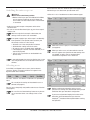
Touch panel
32 33 34
35 36 37
Adjusting brightness and contrast
➩Press the brightness/contrast (32) key once.
➩A bar for adjusting the brightness appears on the screen.
➩Change the brightness with the + and - buttons.
➩Press the brightness/contrast (32) key again.
➩A bar for adjusting the contrast appears on the screen.
➩Change the contrast with the + and - buttons.
➩Press the brightness/contrast button again (32) to save the
values you have set and hide the adjustment bars.
Changing operating modes
➩You can switch your control unit between the video, control
unit and DVI modes using the video/control unit mode switch
(36).
➩The active mode is indicated by an LED (35 or 37).
➩If video mode is active, the video signal received at the video
input (41) is displayed on the monitor.
➩If control unit mode is active, the touch panel displays a menu
interface in which the microscope can be controlled.
➩If the DVI mode is active, the DVI signal (e.g. Leica MDRS4
video system) is displayed and both LEDs light up.
While video mode is active, any warning that may
occur is indicated by an audible signal. This audio
warning signal can be deactivated by your service
partner if desired.
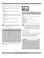
Menu structure
71
72
73 74
78
75
Adjusting the focus
You can focus the microscope using the focus keys on the
footswitch.
You can change the speed at which the focus motor
moves in the "Speed" menu (see page 38).
You can return the focus motor to the reset position
(1/3 up, 2/3 down) by pressing the "Reset" key (59) or the
"Reset Focus" button (see page 38).
You can also refocus the 0° assistant’s attachment using
a fine focus adjustment knob (59).
40
77
76
71 Operational mode (light/magnification settings)
72 Operational mode (drive settings)
73 Configuration menu
74 Static menu bar (does not change)
75 Displays help texts for certain topics
76 Dynamic button bar
77 Display area with status bar
78 Warning messages
Leica M844 – Leica M820 / Ref. 10 713 294 / Version I
40
Use
Switching the microscope on
Warning 13
Motors return to their home positions
➩Before switching on your Leica M820 / Leica M844,
ensure that the travel paths of the XY, zoom and
focus motors are free of obstructions. The tilt motor
is not moved.
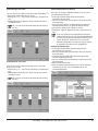
You can click the "User List" button to open a two-page user list
from which you can select from up to 30 saved users.
➩Click the "1-15" or "16-30" button to switch between pages.
➩Switch on your microscope at the power switch of the
horizontal arm.
➩As soon as the main illuminator lights up, your microscope is
ready to use.
After the surgical microscope is switched on, the
settings of the last active user are loaded.
If the power supply of your microscope is accidentally
interrupted for a short period (<20 ±5 seconds), the
microscope carries out a fast startup:
•
•
•
•
All motors are in the same position as before.
All illumination settings remain the same.
XY reverse status is restored where applicable.
If the StepCycleTM function has been selected, it is in
step 0 (see page 45).
• The fast start-up function can be disabled in the
Service menu.
When the user list is open, it can be edited at any time
(see page 42).
When you select a user, an informational screen for
that user appears that specifies the tube settings that
are needed, as well as the current footswitch/
handswitch assignments. Press "Continue".
In operational mode, the status bar displays the current
user and specifies the current location in the menu at
all times.
Selecting users
In the "Main" and "Speed" menu screens, the four buttons
"Cataract", "Retina", "Favorite" and "User List" appear in the
dynamic button bar at all times.
The users "Cataract" and "Retina" are default users provided by
Leica.
You can adjust the settings of these default users as
desired (see page 42).
You can store a frequently used profile under the user "Favorite"
(see page 42).
You can click the "Show Settings" button at any time to
see an overview of the user settings of the current
user.
Before starting every operation make sure your
personal user settings are selected and make yourself
familiarize with your footswitch configuration.
If you have assigned the "StepCycle" function to the
footswitch we recommend tthat you check the
StepCycleTM procedure without patient before starting
the operation.
Leica M844 – Leica M820 / Ref. 10 713 294 / Version I
41
Use
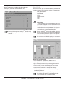
Editing the user list
Configuring users (User Settings menu)
Various functions are available in the user list depending on the
situation.
➩If you select a user, the available functions appear in the
dynamic button bar:
"Move"
Moves the selected user to another available location of
your choosing.
"Set Favorite"
Defines a user in the user list whose settings can be directly
retrieved from the "Main" or "Speed" menu by clicking the
"Favorite" button.
"Delete"
Deletes the selected user. You must click "Confirm" to
confirm this action.
"Rename"
Renames an existing user. The user's settings are not
changed.
You can reach the editing mode of the user list via the
"User Settings" menu and the "Edit User List" button in
the dynamic button bar.
You can configure user settings in this menu.
"Load":
Loads the settings of an existing user so that you can modify
them.
"New User"
Opens a new user with "empty" settings.
"New (Cataract)":
Loads the default settings for "Cataract" so that you can
modify them.
"New (Retina)":
Loads the default settings for "Retina" so that you can modify
them.
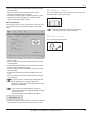
You can also add a user from the operational menu.
If you want to keep the current settings, you can save
them by clicking the "Save" button (which appears as
soon as the basic settings of the current users have
been changed), either for the current user ("Save
Current") or under a new username ("Save as New").
Saving the user settings:
➩Click the "Save" button.
➩Select an available location in the user list at which you want
to create your user. If you like, you can edit the user list first.
➩Enter the desired username using the keyboard.
➩Click the "Save" button to save the user at the desired
location under the name you have entered.
We recommend that you do not change the configuration of the user settings or edit the user list during an
operation.
42
Leica M844 – Leica M820 / Ref. 10 713 294 / Version I
Use
Setting the light start values
Footswitch/handswitch assignment
You can set the start values for the main lamps, the OttoFlexTM II
lamp and the magnification on this screen.
➩Clicking the "+" or "-" key changes the values in increments of
one.
➩Holding down the key with your finger changes the value in
increments of five.
Here, you can configure individual settings for each user for
your footswitch/handswitch.
➩In the right selection field, select the footswitch/
handswitch you are using.
➩You can scroll forwards or backwards in the list by clicking
the arrowheads.
➩If you click the "Cataract" or "Retina" button, the selected
footswitch/handswitch is assigned the default settings.
➩You can then modify these settings as you like.
➩Clicking the "Clear All" button clears the assignments for all
keys.
You can also set the desired value by directly clicking
the bars.
If you are creating only one footswitch/handswitch
configuration for one user, we recommend duplicating
it to the second footswitch/handswitch input by pressing the “Duplicate” button. This ensures that your
footswitch/handswitch functions the way you want it
to, regardless of which input it is plugged into.
Setting the drive start values
You can set the start values for the zoom, focus, XY and tilt
drives on this screen.
➩Clicking the "+" or "-" key changes the values in increments of
one.
➩Holding down the key with your finger changes the value in
increments of five.
Configuring individual keys
➩In the right selection field, select the footswitches/
handswitches you are using.
➩You can scroll forwards or backwards in the list by clicking
the arrowheads.
➩In the left selection field, select the function group that
contains the desired function.
➩You can scroll forwards or backwards in the list by clicking
the arrowheads.
➩Select the desired function.
➩Click the caption of the desired key to assign the selected
function to it. Or, press the corresponding key on the
connected footswitch.
You can also set the desired value by directly clicking
the bars.
Leica M844 – Leica M820 / Ref. 10 713 294 / Version I
43
Use
➩Select the handle in the right selection field.
➩You can scroll forwards or backwards in the list by clicking
the arrowheads.
➩In the left selection field, select the function group that
contains the desired function.
➩You can scroll forwards or backwards in the list by clicking
the arrowheads.
➩Select the desired function.
➩Click the caption of the desired key to assign the selected
function to it.
Overview of function groups
Drive: Magnification +
Magnification Focus +
Focus Tilt +
TiltNo function
Extra:
AD.F.1 toggle
AD.F.1 pulse
AD.F.2 toggle
AD.F.2 pulse
OCF1 toggle
OCF1 pulse
OCF2 toggle
OCF2 pulse
OCF3 toggle
OCF4 pulse
StepCycle
Depth Enhancer Toggle
No function
The "Toggle" function changes the status of a function
(such as On/Off). The "Pulse" function continuously
changes a status (such as increasing the brightness).
Light:
Reset:
Mainlight on/off
OttoFlex Light on/off
Mainlight +
Mainlight OttoFlex Light +
OttoFlex Light All Lights on/off
No function
For the handle, the additional functiongroup with the
functions "All Brakes" (releases all brakes) and
"Selected Brakes" (releases all brakes except the
up/down brake) are also available. (Not available
with Leica M820 F19 and Leica M844 F19.)
If you would prefer a different brake assignment,
please contact your service technician.
Reset Magnification
Reset Focus
Reset Tilt
Reset XY
Reset All
No function
XY function:
Tube Settings
On this page, you can store the diopter values and interpupillary
distance for each user. You can also activate or deactivate the
"Depth Enhancer" as a basic setting for each user.
X+
XY+
YXY Reverse
XY Reverse + OCF1
XY Complete
No function
With the "XY Complete" function, you can assign all four
functions of the joystick simultaneously.
Handle assignment
You can assign up to three functions of your choosing to the
handle. The fourth function must always be "All Brakes".
However, you can assign this function to any position you like.
44
Leica M844 – Leica M820 / Ref. 10 713 294 / Version I
Use
StepCycleTM
On this screen, you can enable or disable the desired
StepCycleTM parameters for the individual users.
StepCycleTM
Using this function, you can save the following parameters for
various frequently recurring phases (cycles) of the operation:
Main light brightness
OttoFlex brightness
Magnification
Focus
Depth Enhancer
OCF1
AD.F.
Caution 7
Risk of injury
➩Look especially after the required safety distance if
you use the StepCycleTM function together with accessories from other manufacturers that reduces the
working distance to less than 140 mm (non-contact
wide-angle observation systems) as focus together
with StepCycleTM a semiautomated function.
When cycling through the StepCycleTM function, only
the actively set parameters for the individual user are
activated.
For the StepCycleTM function to be available, you must
first assign it to a key on your footswitch/handswitch.
Then, the "Rec.Cycle" button appears in the dynamic
button bar.
You can create an individual StepCycleTM procedure for
each user.
StepCycleTM recording mode
➩From the "Main" or "Speed" menu, double-click the
"Rec. Cycle" button to activate it.
➩Press the button on your footswitch/handswitch to which
you have assigned the "Rec.Cycle" function.
➩The currently set values for the StepCycleTM parameters
are saved.
➩You can save a maximum of 10 StepCycleTM settings.
➩Exit the StepCycleTM teach-in mode by double-clicking
the "Rec. Cycle" button.
➩Press "Save" to store your StepCycleTM settings.
It is only possible to store a complete StepCycleTM
cycle. Individual steps cannot be modified.
Leica M844 – Leica M820 / Ref. 10 713 294 / Version I
45
Use
Running through the StepCycleTM
If StepCycleTM settings have been saved for a user, the right
status bar displays information indicating which step the user is
currently in, and how many steps there are total:
• Step 0 means: basic setting of the user
• 1/x means: 1 of x steps
➩In the "Main" or "Speed" menu, deactivate the "Rec. Cycle"
button.
➩Activate the key of your footswitch/handswitch to which the
"StepCycle" function is assigned by clicking it.
➩You run through a continuous loop of the stored StepCycleTM
settings.
The Maintenance menu
Hour meter for the bulbs (Lamp History)
This screen displays the operating hours for each of the
following bulbs: Main 1, Main 2 and Otto Flex Light.
If you load a new user or trigger an Auto Reset, you are
returned to Step 0.
➩Whenever you replace a bulb, reset the bulb's hour meter to
0 by double-clicking the "Reset" button.
Check Switches
On this screen, you can test the footswitches/handswitches
and handles you are using.
Auto Reset
If you move the swing arm up to its end position after the
operation, you trigger the Auto Reset function:
• All of the motors–zoom, focus and XY–move to their
reset position.
• The tilt motor is not moved.
• The current user settings are reloaded.
• The illumination is switched off.
➩If you move your Leica M844 or Leica M820 back down over
the OP field, the illumination switches back on and your Leica
M844 or Leica M820 is ready to use immediately.
This function can be deactivated by your Leica service
technician.
46
➩In the top right selection field, select the connection you are
using.
➩You can scroll forwards or backwards in the list by clicking
the arrowheads.
➩In the bottom right selection field, select the footswitch/
handswitch you want to check.
Leica M844 – Leica M820 / Ref. 10 713 294 / Version I
Use
➩You can scroll forwards or backwards in the list by clicking
the arrowheads.
➩Now press all of the keys, one after the other, of the
footswitch/handswitch you want to test.
➩If the key you have pressed is functioning properly, a green
dot appears on it on the display. The comment "tested"
appears in the caption field of the key.
The "How to..." menu
This screen displays short summaries of various aspects of the
operation of your surgical microscope.
Microscope Settings
Enter the accessories you are using into this screen. This will
ensure that the correct magnification appears in the "Main"
menu.
The "Help" button in the static menu bar provides
access to the "How To..." pages at all times.
The Service menu
This area is password-protected.
➩In the top selection field, enter the tube currently being used
by the surgeon.
➩You can scroll forwards or backwards in the list by clicking
the arrowheads.
➩In the middle selection field, select the magnification of the
eyepieces being used by the surgeon.
➩You can scroll forwards or backwards in the list by clicking
the arrowheads.
➩In the bottom selection field, select the objective you are
using.
➩You can scroll forwards or backwards in the list by clicking
the arrowheads.
If you do not make a selection, the magnification will
be calculated for the standard configuration:
TM
Ultra Low II Tube, ocular with magnification 8.33 and
objective with WD=200.
If you activate the "Standard Values" button, the
standard magnification is displayed, regardless of the
accessories used.
The magnification range is between 7x and 42x.
➩Clicking this button again deactivates it, and you are returned
to the selection screen for the accessories you are using.
Leica M844 – Leica M820 / Ref. 10 713 294 / Version I
47
Safety notes
Intended use
• The Leica surgical microscope is an optical instrument for
improving the visibility of objects through magnification and
illumination. It can be applied for observation and documentation and for human and veterinary medical treatment.
• The Leica surgical microscope may be used only in closed
rooms and must be placed on a solid floor or attached to a
strong ceiling.
• The Leica M820 and Leica M844 surgical microscopes are subject to special precautionary measures for electromagnetic
compatibility. They must be installed and put into operation in
accordance with the guidelines, manufacturer's declarations
and recommended safety distances (Tables 201, 202, 204, and
206 from EN 60601-1-2:2001).
• Portable and mobile as well as stationary HF communications
equipment can have a negative effect on the reliability of the
Leica M820 and Leica M844 surgical microscopes.
Directions for the person responsible for
the instrument
➩Ensure that the surgical microscope is used only by persons
qualified to do so.
➩Ensure that this user manual is always available at the place
where the surgical microscope is in use.
➩Carry out regular inspections to make certain that the
authorized users are adhering to safety requirements.
➩When instructing new users, do so thoroughly and explain
the meanings of the warning signs and messages.
➩Assign individual responsibilities for starting, operating and
servicing the Leica surgical microscope and monitor the
observance of these responsibilities.
➩Only use the surgical microscope if it is free of defects.
➩Inform your Leica representative or Leica Microsystems
(Schweiz) AG, Surgical Division, 9435 Heerbrugg, Switzerland,
immediately if you detect a product defect that could
potentially cause injury or harm.
➩If you use accessories made by third-party manufacturers
with the Leica surgical microscope, be sure that each such
manufacturer confirms the safety-engineering, harmless
usability of the product and observe the product's user
manual.
➩Modifications to or service on the surgical microscope may
be carried out only by technicians who are explicitly
authorized by Leica to do so.
➩Only original Leica replacement parts may be used in
servicing the product.
➩After service work or technical modifications, the unit must
be reconfigured with observance to our technical
requirements.
➩If the unit is modified or serviced by unauthorized persons,
is improperly maintained (as long as maintenance was not
carried out by us), or is handled improperly, Leica will not
accept any liability.
48
➩The influence on other devices by the Leica surgical
microscope has been tested in accordance with
EN 60 601-1-2. The system passed the emissions and
immunity test. The standard preventive measures and safety
regulations pertaining to electromagnetic and other radiation
have to be observed
User qualifications
The Leica surgical microscope may only be used by physicians
and medical assistance personnel with appropriate qualifications who have been instructed in the use of the instrument.
Specific training is not required.
Directions for the operator of the
instrument
➩Follow the instructions described here.
➩Follow the directions provided by your employer regarding
work organization and safety.
Stability (floor stands only)
When moved in OP, the swing arm must be folded up and
locked and the brakes must be applied, otherwise the swing
arm may drift out of control and the stand could topple.
Hazards due to moveable parts
This section describes uses that, inadvertently, could lead to
hazardous situations.
• Add accessories and balance the stand before the operation,
and never over the field of operation.
• Never put your hand between the gas spring and the swing
arm; it could become trapped when the swing arm is moved.
• Do not put your fingers between the microscope and the
focusing drive; they could get crushed.
Floor stand:
• When displacing the stand, push it. Do not pull it. Feet in
lightweight shoes could become trapped beneath the casing
of the base.
• The footbrakes must remain engaged throughout the
operation.
Electrical connections
The control unit may be opened only by a Leica-approved
service technician.
Accessories
Only the following accessories may be used with the Leica
M820 and Leica M844 surgical microscopes:
• The Leica accessories described in this user manual.
• Other accessories, provided that these have been expressly
approved by Leica as being technically safe in this context.
Leica M844 – Leica M820 / Ref. 10 713 294 / Version I
Safety notes
Dangers of use
Warning 1
Motors return to their home positions
➩Before switching on the microscope, ensure that the
travel paths of the X- and Y-axes and the zoom
motor are free of obstructions.
➩Check the Main Light 1/2 and OttoFlexTM II lamps.
Replace defective bulbs before the operation
begins.
➩Test all handswitch and footswitch functions.
➩Check the function of the brakes using the handles
and remote brake release (see page 33).
Warning 2
Danger of fatal electric shock
➩Operate the system only with all equipment in its
proper position (all covers fitted, doors closed).
Warning 3
Risk of injury through surgical microscope moving
down!
➩Complete all preparations and adjustments to the
stand before the operation.
➩Never balance or re-equip the instrument over the
field of operation.
➩Before re-equipping, always lock the swing arm.
➩After re-equipping, always rebalance the
microscope on the swing arm.
➩Do not release the brakes when the instrument is in
an unbalanced state.
➩Before re-equipping during the operation, first swing
the microscope away from the operating field.
Warning 4
Danger of burns
➩The lamp housing and cover may become hot during
use.
Warning 5
There is a danger of injury to the patient as a result of
changing the working distance using the motorized
adjustment of the telescopic stand if the working distance falls below the minimum of 140 mm due to the
use of accessories (such as wide-angle observation
systems).
➩The footswitch function for moving the telescopic
stand up and down may not be used in combination
with accessories that cause the working distance to
fall below the minimum of 140 mm.
➩Before up/down movements, always check first to
ensure that the range of movement is free of
obstructions.
Warning 6
Risk of injury through surgical microscope moving
down!
➩Never balance or re-equip the instrument over the
field of operation.
➩After re-equipping, always rebalance the
microscope on the swing arm.
Warning 7
Risk of injury through surgical microscope moving
down!
➩Always lock the swing arm:
• when transporting the microscope
• when changing equipment
Warning 8
Risk of injury through surgical microscope moving
down!
➩Complete all preparations and adjustments to the
stand before the operation.
➩If settings need to be altered during the operation,
first swing the microscope away from the operating
field.
➩If the microscope needs to be re-equipped, do this
before the operation.
➩Before re-equipping, always lock the swing arm.
➩Do not use the handle or remote brake release
when the instrument is in an unbalanced state.
Warning 9
Beware of:
• Uncontrolled lateral movement of the swing arm!
• Tilting of the stand!
• Feet in lightweight shoes could become trapped
beneath the casing of the base.
➩Before transport, always set the Leica M820 F19 and
Leica M844 F19 surgical microscopes to the
transport position.
➩Never move the stand in the extended condition.
➩Always push the instrument to displace it;
never pull it.
➩Never roll over cables lying on the floor.
Warning 10
Danger of fatal electric shock
➩The surgical microscope may be connected to a
grounded socket only.
Warning 11
Risk of injury through surgical microscope moving
down!
➩Do not use the handle or remote brake release
when the instrument is in an unbalanced state.
Leica M844 – Leica M820 / Ref. 10 713 294 / Version I
49
Safety notes
Dangers of use
Warning 12
Light which is too intense can damage the retina.
➩Safeguard your patients:
• short exposure times
• low brightness settings
• protective filters (GG420 built in)
Warning 13
Motors return to their home positions
➩Before switching on your Leica M844, ensure that
the travel paths of the XY, zoom and focus motors are
free of obstructions. The tilt motor is not moved.
Warning 14
Danger of fatal electric shock
➩Disconnect the power cable from the power socket
before changing fuses.
Warning 15
Halogen lamps become very hot.
➩Always switch off the control unit before changing a
bulb.
➩Allow bulbs to cool off before changing them.
Caution 1
Connecting unauthorized secondary devices to the
auxiliary power socket can lead to damage to the
surgical microscope and to the secondary device!
➩Never connect secondary devices to the auxiliary
power socket unless they conform to the specifications. For requirements of use, see the Technical
data, page 67.
Caution 2
There is a risk of damage to the surgical microscope
from uncontrolled tilting!
➩Firmly hold the handles before triggering the
"All Brakes" function.
Caution 3
Surgical microscope can move without warning!
➩Always lock the footbrake when you are not moving
the system.
Caution 4
Danger of collision!
The surgical microscope can collide with surrounding
components, the ceiling or lamps.
➩Check the danger area before moving the swing arm.
➩Carefully move the ceiling mount upwards, and
observe ceiling and lamps.
Caution 5
Risk of infection!
➩Leave sufficient space around the stand to ensure
that the sterile drape does not come into contact
with non-sterile components.
Caution 6
Destruction of the zoom motor!
➩Use the manual adjustment of the zoom motor only if
the zoom motor is defective.
Caution 7
Risk of injury
➩Look especially after the required safety distance if
you use the StepCycleTM function together with
accessories from other manufacturers that reduces
the working distance to less than 140 mm (noncontact wide-angle observation systems) as focus
together with StepCycleTM a semiautomated function.
Caution 8
Damage of the touch panel
➩Operate the touch panel using your fingers only.
Never use hard, sharp or pointed objects made out of
wood, metal or plastic.
Caution 9
Damage of the touch panel
➩Never clean the touch panel using cleaners that
contain abrasive substances. These substances can
scratch the surface and cause it to be become dull.
50
Leica M844 – Leica M820 / Ref. 10 713 294 / Version I
Guidance and manufacturer's declaration
Manufacturer's declaration of electromagnetic compatibility (EMC)
This "Guidance and manufacturer's declaration" document is based on EN 60601-1-2:2001.
Table 201 from EN 60601-1-2:2001
Guidance and manufacturer's declaration – electromagnetic emissions
The Leica M820 and Leica M844 surgical microscopes are intended for use in the electromagnetic environment specified below.
The customer or the user of the Leica M820 and Leica M844 surgical microscopes should assure that they are used in such an
environment.
Emissions test
Compliance
Electromagnetic environment – guidance
HF emissions
according to CISPR 11
Group 1
The Leica M820 and Leica M844 surgical microscopes use HF energy
only for its internal function. Therefore, its HF emissions are very low and
are not likely to cause any interference in nearby electronic equipment.
HF emissions
according to CISPR 11
Class A
The Leica Leica M820 and Leica M844 surgical microscopes are suitable
for use in establishments other than domestic and those directly
connected to the public low-voltage power supply network that supplies
buildings used for domestic purposes.
Harmonic emissions
IEC 61000-3-2
Class A
Voltage fluctuations/
flicker emissions
IEC 61000-3-3
Compliant
Leica M844 – Leica M820 / Ref. 10 713 294 / Version I
51
Guidance and manufacturer's declaration
Table 202 from EN 60601-1-2:2001
Guidance and manufacturer's declaration – electromagnetic immunity
The Leica M820 and Leica M844 surgical microscopes are intended for use in the electromagnetic environment specified below.
The customer or the user of the Leica M820 and Leica M844 surgical microscopes should assure that they are used in such an
environment.
Immunity test
IEC 60601 test level
Compliance level
Electromagnetic environment – guidance
Electrostatic
discharge (ESD)
IEC 61000-4-2
± 6 KV
contact
± 6 KV
contact
± 8 kV air
± 8 kV air
Floors should be of wood, concrete or
ceramic tile. If floors are covered with
synthetic material, the relative humidity
should be at least 30%.
± 2 KV for
power supply lines
± 2 KV for
power supply lines
Mains power quality should be that of a
typical commercial or hospital environment.
± 1 KV for input/
output lines
± 1 KV for input/
output lines
± 1 KV
differential mode
± 1 KV
differential mode
± 2 kV
common mode
± 2 kV
common mode
<5% UT (>95%
dip in UT)
for 1/2 period
<5% UT (>95%
dip in UT)
for 1/2 period
40% UT (60%
dip in UT)
for 5 cycles
40% UT (60%
dip in UT)
for 5 cycles
70% UT (30%
dip in UT)
for 25 cycles
70% UT (30%
dip in UT)
for 25 cycles
<5% UT (>95%
dip in UT)
for 5 sec.
<5% UT (>95%
dip in UT)
for 5 sec.
Power frequency
(50/60 Hz)
magnetic field
IEC 61000-4-8
3 A/m
Not applicable
Note:
UT is the a.c. mains voltage prior to application of the test level.
Electrical fast transient/
burst
IEC 61000-4-4
Surges
IEC 61000-4-5
Voltage dips,
short interruptions
and voltage variations on
power supply lines
IEC 61000-4-11
52
Mains power quality should be that of a
typical commercial or hospital environment.
Mains power quality should be that of a
typical commercial or hospital environment.
If the user of the Leica M820 and Leica M844
surgical microscopes requires continued
operation during power mains interruptions,
it is recommended that the Leica M820 and
Leica M844 surgical microscopes be
powered from an uninterruptible power
supply or a battery.
Leica M844 – Leica M820 / Ref. 10 713 294 / Version I
Guidance and manufacturer's declaration
Table 204 from EN 60601-1-2:2001
Guidance and manufacturer's declaration – electromagnetic immunity
The Leica M820 and Leica M844 surgical microscopes are intended for use in the electromagnetic environment specified below.
The customer or the user of the Leica M820 and Leica M844 surgical microscopes should assure that it is used in
such an environment.
Immunity test
IEC 60601 test level
Compliance level
Electromagnetic environment – guidance
Portable and mobile HF communications
should be used no closer to any part of the
Leica M820 and Leica M844 surgical
microscopes, including cables, than the
recommended separation distance
calculated from the equation applicable to
the frequency of the transmitter.
Recommended separation distance:
Conducted HF –
equipment
IEC 61000-4-3
3 Veff
150 kHz to 80 MHz
3 Veff
d = 2.4 P
for 150 kHz to 80 MHz
Radiated HF –
IEC 61000-4-3
3 V/m
80 MHz to 2.5 GHz
3 V/m
d= 2.4 P
for 80 MHz to 2.5 GHz
Where P is the maximum output power rating
of the transmitter in watts (W) according to
the transmitter manufacturer and d is the
recommended separation distance in meters
(m). Field strengths from fixed HF transmitters,
as determined by an electromagnetic site
survey, should be less than the compliance
level in each frequency range. Interference
may occur in the vicinity of equipment
marked with the following symbol:
Note 1:
At 80 MHz, the higher frequency range applies.
Note 2:
These guidelines may not apply in all situations. Electromagnetic propagation is affected by
absorption and reflection from structures, objects and people.
a Field strengths from fixed transmitters, such as base stations for radio (cellular/cordless) telephones and land mobile radios,
amateur radio, AM and FM broadcast and TV broadcast cannot be predicted theoretically with accuracy. To assess the
electromagnetic environment due to fixed HF transmitters, an electromagnetic site survey should be considered. If the
measured field strength in the location in which the Leica M820 and Leica M844 surgical microscopes are used exceeds the
applicable HF compliance level above, the Leica M820 and Leica M844 surgical microscopes should be observed to verify
normal operation. If abnormal performance is observed, additional measures may be necessary, such as reorienting or
relocating the Leica M820 and Leica M844 surgical microscopes.
b Over the frequency range 150 kHz to 80 MHz, field strengths should be less than 3 V/m.
Leica M844 – Leica M820 / Ref. 10 713 294 / Version I
53
Guidance and manufacturer's declaration
Table 206 from EN 60601-1-2:2001
Recommended separation distances between portable and mobile HF telecommunications equipment and
the Leica M820 and Leica M844 surgical microscopes
The Leica M820 and Leica M844 surgical microscopes are intended for use in an electromagnetic environment in which radiated
HF disturbances are controlled. The customer or user of the Leica M820 and Leica M844 surgical microscopes can help prevent
electromagnetic interference by maintaining a minimum distance between portable and mobile HF communication equipment
(transmitters) and the Leica M820 and Leica M844 as recommended below, according to the maximum output power of the
communications equipment.
Separation distance according to frequency of transmitter in m
Rated maximum output
power of transmitter W
150 kHz to 2.5 GHz
d = 2.4 P in m
0,01
0.24
0,1
0.8
1
2.4
10
8.0
100
24.0
For transmitters rated at a maximum output power not listed above, the recommended separation distance d in meters (m)
can be estimated using the equation applicable to the frequency of the transmitter, where P is the maximum output power
rating of the transmitter in watts (W) according to the transmitter manufacturer.
Note 1:
These guidelines may not apply in all situations. Electromagnetic propagation is affected by
absorption and reflection from structures, objects and people.
Warning message:
Using accessories or cables other than those listed here or those permitted by the manufacturer of the Leica M820 and Leica M844
surgical microscopes may result in increased electromagnetic emissions or decreased immunity.
Warning message:
The Leica M820 and Leica M844 surgical microscopes may not be used while positioned directly next to other instruments.
If it is necessary to operate them in the vicinity of other instruments, the microscopes should be monitored to ensure that they function properly in this arrangement.
54
Leica M844 – Leica M820 / Ref. 10 713 294 / Version I
Safety notes
Signs and labels
Floor stand F40
Horizontal arm and swing arm F19
Caution! Follow the User Manual.
Danger sign for contusions
Danger sign for hot surface
Symbol for alternating current
Symbol for fuses
Leica M844 – Leica M820 / Ref. 10 713 294 / Version I
55
Safety notes
Signs and labels
Leica Telescope Mount
56
Leica M844 – Leica M820 / Ref. 10 713 294 / Version I
Safety notes
Signs and labels
Horizontal arm and swing arm F40 / C40 / CT40
Max. 12.2 kg (26.90lb)
CAUTION HIGH PRESSURE
DO NOT OPEN
TYPE 10448139
SN
DDMMYYXX
Made in CH
max. power output
100 VA
T1A/250V
Grounding reliability can
only be achieved when
EQUIPMENT is connected to
equivalent receptacle marked
“Hospital only“ or “Hospital
Grade“.
La fiabilité de la mise à
la terre n'est assurée que
si l'équipement est
connecté à une prise
équivalente, marquée
«Hôpital seulement» ou
«Qualité hôpital».
Caution! Follow the User Manual.
Danger sign for contusions
Danger sign for hot surface
Symbol for alternating current
Symbol for fuses
Leica M844 – Leica M820 / Ref. 10 713 294 / Version I
57
Care and maintenance
Maintenance instructions
•
•
•
•
•
•
•
•
•
Put a dust cover over the instrument during breaks in work.
Keep accessories in a dust-free place when not in use.
Remove dust with a pneumatic rubber pump and a soft brush.
Clean the objectives and eyepieces with special optics
cleaning cloths and pure alcohol.
Protect the surgical microscope from damp, vapors, acids,
alkalis, and corrosive substances.
Do not keep chemicals near the instrument.
Protect the surgical microscope from improper handling.
Install other device sockets or unscrew optical systems and
mechanical parts only when explicitly instructed to do so in
this user manual.
Protect the surgical microscope from oil and grease.
Never oil or grease the guide surfaces or mechanical parts.
Remove coarse debris with a moistened disposable cloth.
For disinfecting the surgical microscope, use compounds
from the surface disinfecting group based on the following
active ingredients:
aldehydes,
alcohols,
quaternary ammonia compounds.
Due to potential damage to the materials, never use
substances based on
halogen splitting compounds,
strong organic acids,
oxygen splitting compounds.
Follow the disinfectant manufacturer’s instructions.
It is recommended to conclude a service contract with
Leica Service.
Caution 8
Damage of the touch panel
➩Operate the touch panel using your fingers only.
Never use hard, sharp or pointed objects made out
of wood, metal or plastic.
Caution 9
Damage of the touch panel
➩Never clean the touch panel using cleaners that
contain abrasive substances. These substances can
scratch the surface and cause it to be become dull.
Maintenance
The operating microscopes Leica M820 F40, Leica M820 F19,
Leica M820 CT 40 as well as Leica M844 F40, Leica M844 F19,
Leica M844 CT40 in principle are maintenance free.
The operating microscopes Leica M820 C40 and Leica M844 C40
(Leica ceiling mount with lift arm) – in order to keep safety and
reliability – are subject to regular maintenance inspections
with the following minimum time intervals:
At the latest 5 years after first bringing into service and then at
least once a year:
Inspection by trained technicians:
•
•
•
•
Functional and visual inspection of the entire ceiling mount
Visual inspection of all cables
Electronically safety test
Check and test of the lift system, in particular all bearings
for free movement
• Lubrication of the spindle
Cleaning the touch panel
➩Before cleaning the touch panel, switch off your Leica M820
and Leica M844 and disconnect it from the power supply.
➩Use a soft, lint-free cloth to clean the touch panel.
➩Do not apply cleaning agent directly to the touch panel;
rather, apply it to the cleaning cloth.
➩Use a commercially available glass/eyeglass cleaner or plastic cleaner to clean the touch panel.
➩Do not apply pressure to the touch panel while cleaning it.
The touch panel is resistant to most disinfectants used
in the medical field.
58
Only lubricate the spindle with
STABURAGS NBU 12/300 KP (Klüber Lubrication
München KG, Deutschland)
No other lubricants are permissible.
➩In order to ensure the reliability of the entire system we
recommend a frequent maintenance already after warranty
end carried out by our specialists. Please contact your local
Leica (representative) service for an individual offer.
➩Only use original spare parts for servicing.
Leica M844 – Leica M820 / Ref. 10 713 294 / Version I
Care and maintenance
➩Open the cover on the rear of the optics carrier by sliding the
lamp cover opener to the right.
➩To replace lamp M1, the bulb slider must be all the way to the
left.
➩To replace lamp M2, the bulb slider must be all the way to the
right.
➩Pull on the tab to remove the bulb socket complete with bulb.
➩Insert the new bulb socket and bulb.
Changing fuses
Fuses
h
Type
10448139
SN
211004003
Made in CH
OttoFlexTM II
Fuse holder
➩Pull out the fuse holder on the underside of the horizontal arm.
➩Remove the two fuses from the holder and replace them.
Use only 6.3 A time-lag fuses.
Use only precision-formed original Leica 12 V/ 50 W
halogen bulbs.
Never touch the glass bulb of halogen lamps with your
bare fingers.
➩Open the cover on the rear of the optics carrier by sliding the
lamp cover opener to the right.
Warning 14
Danger of fatal electric shock
➩Before replacing the fuse, unplug the power cable from
the power socket.
Changing bulbs
Warning 15
Halogen lamps become very hot.
➩Always switch the main switch off before changing a
bulb.
➩Allow bulbs to cool for 20 minutes before changing
them (burn hazard!)
OTTOFLEX
78
Main Light
Use only precision-formed original Leica 12 V/ 50 W
halogen bulbs.
Never touch the glass bulb of halogen lamps with your
bare fingers.
Lamp
cover
opener
79
80
M1
M2
81
82
78 Reflector
79 Bulb socket
80 Lever
81 Bulb slider
82 Lamp cover opener
➩Make sure that the quick-change lamp mount is on Main
Light 1 so that the bulb slider is all the way to the right.
➩Fold the reflector on the pin upwards and to the right.
➩Pull on the tab to remove the bulb socket complete with bulb.
➩Insert the new bulb socket and bulb.
➩Fold the reflector back down until it engages.
Whenever you replace a bulb, reset the bulb's hour
meter to 0 (see page 46).
OTTOFLEX
M1
M2
Bulb socket Bulb slider
Leica M844 – Leica M820 / Ref. 10 713 294 / Version I
59
Care and maintenance
Notes on reprocessing of resterilizable
products
Products
Reusable products supplied by Leica Microsystems (Schweiz)
AG such as rotary knobs, objective protective glasses and
capping pieces.
Reprocessing restrictions:
With regard to the processing of medical products used on
patients or suspected patients suffering from Creutzfeldt-Jacob
disease (CJD) or its variant (vCJD), the local legal regulations
must be observed. As a rule, resterilizable products used for
these patients can be eliminated without danger by burning.
Occupational safety and health protection
Particular attention must be paid to the occupational safety and
health protection of the persons responsible for preparing
contaminated products. Current regulations of hospital hygiene
and prevention of infection must be observed in the
preparation, cleaning and disinfection of the products.
Limitation of reprocessing
Frequent reprocessing has little effects on these products.
The end of the product life cycle is usually determined by wear
and year and damage through use.
Instructions
Workplace
Remove surface contamination with a disposable cloth / paper
cloth.
Storage and transport
No special requirements.
It is recommended to perform the reprocessing of a product
immediately following its use.
Preparation for cleaning
Remove the product from the surgical microscope.
Cleaning: manual
Equipment: running water, rinsing agent, spirit, micro-fiber cloth
Procedure:
• Rinse surface contamination off of the product (temp. <40 °C).
Use some rinsing agent depending upon degree of
contamination.
• If the optics is heavily contaminated, e.g. finger marks,
fat streaks, etc., use spirit for cleaning.
• Dry off products, except for optical components, with a
disposable cloth/paper cloth. Dry off optical surfaces with a
micro-fiber cloth.
60
Cleaning: automatic
Equipment: Cleaning/disinfecting device
It is not recommended to clean products with optical
components in a cleaning/disinfecting device. In addition,
optical components must not be cleaned in ultrasonic baths in
order to prevent damage.
Disinfection
The alcohol disinfection solution "Mikrozid, Liquid" may be used
in accordance with the instructions on the label.
Please note that optical surfaces must be rinsed thoroughly
with fresh drinking water, followed by fresh demineralized
water, after disinfection. The products must be dried thoroughly
before the subsequent sterilization.
Maintenance
No special requirements.
Control and functional test
Check the snap-on behavior of rotary knobs and handles.
Packaging
Separate: A standard PE bag may be used. The bag must be
large enough for the product so that the closure is not under
tension.
Sterilization
See Table 1
Storage
No special requirements.
Additional information
None
Contact information of manufacturer
Address of local agent
Leica Microsystems (Schweiz) AG verified that the aforementioned instructions for the preparation of a product are suitable
for its reuse. The processing person is responsible for reprocessing with the equipment, materials and personnel and for
achieving the desired results in the reprocessing installation.
In general, this requires validations and routine monitoring of
the process. Every deviation from the supplied instructions
should also be examined carefully by the processing person to
determine effectiveness and possible detrimental
consequences.
Leica M844 – Leica M820 / Ref. 10 713 294 / Version I
Care and maintenance
Table: Sterilization
Item no.
10180591
10428328
10384656
10443792
10429792
10445368
10445289
Designation
Clip-on handle
Rotary knob, binoc. tube T
Rotary knob, transparent
Lever extension
Capping piece, slit lamp
Cover, binoc. tube 0–180°
Handswitch holder
10446058
10446469
10446467
Protective glass, multifoc. obj.
Objective protective glass Leica M680
Objective protective glass Leica M8xx
10443714
10445341
10445549
10445340
Rotary ring, objective 0°
Handle for Leica M655, sterilizable
Handle for Leica M695
Cap for Leica M655/M695, sterilizable
1)
Permissible sterilization methods
Steam (autoclave) Ethylene oxide
134 °C, t > 10 min.
max. 60 °C
X
X
X
X
X
X
X
X 1)
X 1)
X 1)
X
X
X
X
Products with optical components can be steam-autoclaved using the conditions listed above. However, this may lead to the
formation of a layer of dots and streaks on the glass surface, which may reduce the optical performance.
Leica M844 – Leica M820 / Ref. 10 713 294 / Version I
61
What to do if...?
If electrically operated functions do not work properly,
always check these points first:
• Is the power switch switched on?
• Is the power cable attached correctly?
• Are all connecting cables attached correctly?
General
Fault: The functions cannot be activated with the handswitch
or footswitch
Cause 1: A cable connection has loosened.
Cause 2: Assignment entered incorrectly on the control unit.
Fault remedy:
➩Check the power cable.
➩Check the handle connections.
Fault remedy:
➩Check the assignment of the footswitch/handswitch on the
control unit (see page 43).
Microscope
Fault: There is no light in the microscope.
Cause 1: A cable connection has loosened.
Fault remedy:
➩Check the electrical connections.
➩Check the power cable.
Cause 2: Quick-change lamp mount not positioned correctly.
Fault remedy:
➩Slide the quick-change lamp mount to the other side
(see page 39).
Cause 3: Bulb is defective (message "Check Mainlamp 1/2"
appears).
Fault remedy:
➩If the main light fails during the operation, switch to the other
lamp using the quick-change lamp mount.
➩After the operation, check the bulbs and replace the defective
bulb (see page 59).
62
Leica M844 – Leica M820 / Ref. 10 713 294 / Version I
What to do if...?
TM
Fault: There is no OttoFlex II light in the microscope.
Cause 1: A filter slide is inserted.
Fault remedy:
➩Check to see whether a filter slide is inserted; if so, pull it out.
Switch the OttoFlexTM II back on.
Cause 2: The switch is set to the Slitlamp position.
Fault remedy:
➩Check the position of the Otto Flex/
Slitlamp switch (see page 23) and set it to Otto Flex.
Cause 3: Bulb is defective
Fault remedy:
➩Check the bulbs and replace any that are
defective (see page 59).
Fault: The image goes out of focus.
Cause 1: Eyepieces not seated properly
Fault remedy:
➩Check the seating of the eyepieces and screw them in all the
way if necessary.
Cause 2: Dioptric correction is not set correctly.
Fault: Zoom cannot be adjusted electrically
Cause 1: Zoom motor has failed.
Fault: Unwanted reflections
Cause 1: The sterile drape produces stray reflections
Fault: The surgical microscope does not move, or requires
undue force.
Cause 1: A cable is jammed.
Cause 2: The transport lock has not been released.
Cause 3: A brake is not released.
Fault remedy:
➩Carry out the dioptric correction by following the instructions
exactly (see page 24).
Fault remedy:
➩Push and turn the zoom rotary knob to manually adjust the
zoom (see page 13).
Fault remedy:
➩Clamp the objective cover of the sterile drape to the objective
with the cover tilted slightly forwards.
Fault remedy:
➩Move the jammed cable to another position.
Fault remedy:
➩Release the transport lock (see page 35).
Fault remedy:
➩Contact your Leica representative.
Leica M844 – Leica M820 / Ref. 10 713 294 / Version I
63
What to do if...?
Two-in-One control unit
Fault: There is no picture in the display
Cause 1:
The touch panel is in video mode, but is not receiving
a video signal.
Fault remedy:
➩ Switch to control unit mode (see page 40).
Cause 2:
A cable connection has loosened.
Fault remedy:
➩ Check to ensure that the cable connections are tight.
Cause 3:
The display is defective.
Fault remedy:
➩ Contact your Leica representative.
➩ You can still work with your Leica microscope.
All functions can still be operated using the
footswitch/handswitch.
Error messages on the control unit
Fault:
Fault remedy:
➩ Switch to the second lamp using the corresponding
quick-change lamp mount.
➩ Replace the defective bulb as soon as possible.
• Check Main Lamp 1
• Check Main Lamp 2
• Check Slitlamp
Fault:
Check Ottoflex
Fault remedy:
➩ Replace the defective bulb as soon as possible.
Fault:
• Compact Stand Brake Controller not present
• Zoom-Lamp Controller not present
• Focus-Tilt Controller not present
• XY Controller not present
• Microscope Device Controller not present
(Command Interface)
• Microscope Device Controller not present
(Config Interface)
Fault remedy:
➩ Contact your Leica representative.
F40 stand
Fault: The surgical microscope does not move, or requires
undue force.
Cause 1: A cable is jammed.
Cause 2:
The transport lock has not been released.
Cause 3:
A brake is not released.
Fault remedy:
➩ Move the jammed cable to another position.
Fault remedy:
➩ Release the transport lock (see page 36).
Fault remedy:
➩ Contact your Leica representative.
C40 ceiling mount
Fault: Leica M844 C40 or Leica M820 C40 rotates.
Fault remedy:
➩ Contact your Leica representative.
➩ Have the adjustment of the suspension checked and
readjusted.
Fault: The Leica M844 C40 or Leica M820 C40 drifts up or down.
Fault remedy:
➩ Contact your Leica representative.
➩ Have your Leica service technician slightly brake the
corresponding axis using the built-in drift brakes.
64
Leica M844 – Leica M820 / Ref. 10 713 294 / Version I
What to do if...?
CT40 ceiling mount
Fault: The Leica CT40 cannot be moved up or down.
Cause 1: The Leica CT40 is protected by a temperature switch
that switches off in case of overheating.
Cause 2: Poor plug contact.
Cause 3: Customer's fuse defective.
Fault remedy:
➩ Wait approximately 30-45 minutes until the telescope motor
has cooled off.
Fault remedy:
➩ Check the clamping terminal.
➩ Check the plug of the remote control.
Fault remedy:
➩ Replace the fuse.
F19 stand
Fault: The swing arm moves up/down by itself.
Cause 1: Swing arm is not balanced.
Fault remedy:
➩ Balance swing arm (see page 34).
Cause 2: Bad cabling.
Fault remedy:
➩ Check the position of the cables, especially in case of
subsequently added video cables.
Fault: The swing arm sinks even at the highest level of the
balancing scale.
Cause: Maximum load of optics carrier exceeded.
Fault: The microscope is difficult to position.
Cause: Articulation brakes are too tightened.
Fault remedy:
➩ Reduce the total weight of the microscope and accessories
Fault remedy:
➩ Adjust the articulation brakes so that you can position the
microscope easily (see page 34).
TV, photography
Fault: The image on the monitor is too dark.
Cause 1: The video camera and/or monitor are not set
correctly.
Cause 2: Filter in dual attachment is set incorrectly.
Fault: Photos are blurry.
Cause 1: Parfocality of microscope has not been adjusted.
Cause 2: Object is out of focus.
Fault remedy:
➩ Optimize the settings for the camera and/or
monitor (see manufacturer's operating instructions).
➩ Also refer to page 18.
Fault remedy:
➩ Adjust the brightness or replace the filter in the dual
attachment.
Fault remedy:
➩ Check the parfocality of the microscope (see page 24).
Fault remedy:
➩ Focus precisely, insert graticule if necessary.
Leica M844 – Leica M820 / Ref. 10 713 294 / Version I
65
Technical data
Microscope
Leica QuadZoom™
Leica OptiChrome™
Magnification changer
Field diameter
Working distances WD
Focusing
Leica ErgonOptic™
Eyepieces
Objectives
X/Y coupling
Tilt drive
Remote control
Weight
Accessories
Optical system with four beam paths:
100% stereopsis for surgeon and
assistant (Leica M844 only)
High-performance optics for high
contrast, brilliant colors, crisp image
definition, and outstanding resolution
6:1 range, motorized
7 mm to 80 mm
175 mm, 200 mm, 225 mm
Motorized, 54 mm,
with automatic reset
Binocular tube 10° to 50°,
TM
Low and UltraLow II;
variable 0-180°;
variable 30-150°
Wide-field eyepieces for spectacle
wearers 8.33×, 10×, 12.5*×
TM
Leica OptiChrome
WD 175 mm/f = 200 mm
WD 200 mm/f = 225 mm
WD 225 mm/f = 250 mm
WD: working distance
f: focal length
Motorized, 50 mm×50 mm,
with automatic reset
Motorized, +15°/–50°
12-function footswitch with
long or cross pedals,
12-function handswitch,
16-function footswitch with
cross pedals
28.3 kg (with accessories and
XY unit)
0° assistant’s
attachment
Double wing
TV/photo
Wide-angle observation
system
Inverter
Lasers
Slit lamp
Asepsis
Lamps
Main light
Integrated illumination concept
for intense, uniform red reflex
TM
Illuminator module for increasing
Leica OttoFlex II
red reflex, decreasing stray light
through the sclera and increasing
image contrast.
Variable field diameter
from 4 mm - 35 mm
at WD 200 mm
Precision-formed halogen
bulb 12 V/50 W
Quick-change lamp mount With two precision-formed
(main light only)
halogen bulbs 12 V/50 W
Filters
IR barrier filter and UV barrier filter
(GG420), integrated
66
Leica M844 – Leica M820 / Ref. 10 713 294 / Version I
100% stereopsis at the same
magnification,
integrated fine focus,
rotary ring for binocular tube
(±15°),
documentation port
for 3 simultaneous observers
Leica 2D video systems
Leica D2D digital video system
Leica zoom video adapter
f = 35-100 mm
Photo/TV dual attachment
f = 60/ 85/ 107 mm for TV
f = 250/ 350 mm for 35 mm camera
TV tube f= 107 mm
Phototube f= 250/350 mm
BIOM*, EIBOS*
AVI*, SDI*, OIVSL*, ROLS*
Adapters for installation are
available from laser manufacturer
Motorized, ±23°,
slit width 0.01-15 mm,
slit length 3-15 mm,
180° revolving, quick-change
lamp mount
All operating elements can be
sterilized, sterile drapes are
available
* Accessories from third-party
manufacturers
Technical data
Electrical data
Optical data
Power socket
F40 floor stand
With UltraLow II binocular tube
F19 floor stand
CT40 ceiling mount
C40 ceiling mount
Fuse
Power consumption
Leica M844 / M820 F40
Leica M844 / M820 F19
Leica M844 / M820 C40
Leica Ceiling Mount
Leica M844 / M820 CT40
Leica M844 / M820 CT 40
Protection class
TM
Central on the horizontal arm
100–240 VAC (±10%), 50/60 Hz
Central on the horizontal arm
100–240 VAC (±10%), 50/60 Hz
Terminal strip on the ceiling
100/120 VAC, 220/240 VAC (±10%),
50/60 Hz
Terminal block on the ceiling
100/120 VAC, 220/240 VAC (±10%),
50/60 Hz
2× 6.3 A, time-lag
400 VA
300 VA
400 VA (without ceiling mount)
400 VA (ceiling mount only)
(120V ~60 Hz) 1500 VA
(whole system incl. telescope)
(230V ~50 Hz) 1400 VA
(whole system incl. telescope)
Objective
Leica OptiChrome™
WD = 175 mm/f = 200 mm
Eyepiece
Total magnification
Field of view
(∅ mm)
8.33×
3.4× – 20.4×
53.9 – 9.0
10×
4.1× – 24.5×
51.4 – 8.6
12.5×
5.1× – 30.7×
41.6 – 6.9
Objective
Leica OptiChrome™
WD = 200 mm/f = 225 mm
Eyepiece
Total magnification
Field of view
(∅ mm)
8.33×
3.0× – 18.2×
60.6 – 10.1
10×
3.6× – 21.8×
57.8 – 9.6
12.5×
4.5× – 27.3×
46.8 – 7.8
Class 1
Auxiliary power socket
Max. permitted power
consumption of the
secondary device:
Max. permitted ground
leakage current of the
secondary device:
Required conformity of the
secondary device:
Objective
Leica OptiChrome™
WD = 225 mm/f = 250 mm
Eyepiece
Total magnification
Field of view
(∅ mm)
8.33×
2.7× – 16.3×
67.3 – 11.2
10×
3.3× – 19.6×
64.3 – 10.7
12.5×
4.1× – 24.5×
52.0 – 8.7
100 VA
200 µA at 110 V
300 µA at 230 V
EN 60601-1 (Europe)
UL 60601-1 (USA)
If the device does not conform, it must be connected via an
isolating transformer.
If the ground leakage current exceeds the permitted limit value,
the following measures are required:
• Device does not conform to EN 60601-1 (Europe) / UL 60601-1
(USA): Connection via isolating transformer.
• Device conforms to EN 60601-1 (Europe) / UL 60601-1 (USA):
Connection via potential equalization or isolating transformer.
Leica M844 – Leica M820 / Ref. 10 713 294 / Version I
67
Technical data
Stands/ceiling mounts
F40 floor stand
Castors
Weight
Total weight
Brakes
Load
Space requirement:
Range
Stroke
Balancing
Turning range
4x 82.5 mm
Base: 174 kg
Column: 83 kg
Approx. 330 kg with max. load
Four electromagnetic
brakes, operated by
turning the handles,
one stop lever for vertical
movement
Max. 12.2 kg from
microscope/dovetail ring interface
Foot: 637 x 637 mm
min. height in rest position: 1949 mm
Extension 1492 mm max.
846 mm
via gas spring
Axis 1 (near column): ±170°
Axis 2 (in the middle): +150°/-170°
Axis 3 (over XY unit): ±270°
C40 ceiling mount
Ceiling attachment
Weight
Brakes
Load
Range
Travel range
Balancing
Turning range
Swing arm:
F19 floor stand
Castors
Weight of base
Total weight
Brakes
Load
Space requirement
Range
Stroke
Balancing
Turning range
68
4x82,5 mm
174 kg
Column: 20 kg
Approx. 270 kg with max. load
4 mechanical articulation brakes,
locking lever for vertical
movement
Swing arm: Max 11.5 kg from
microscope dovetail ring
Foot: 637 x 637 mm
min. height in rest position: 1949 mm
Extension 1305 mm max.
652 mm
via gas spring
Axis 1 (near column): 360°
Axis 2 (in the middle): ± 170°
Axis 3 (over XY unit): ± 270°
Leica M844 – Leica M820 / Ref. 10 713 294 / Version I
Max. distance from concrete ceiling to intermediate ceiling:
1200 mm
Attachment to concrete shell
construction ceiling:
470 mm hole circle
6 x M24 FHA 24/0/50B
or FHA 24/0/150B
Ceiling mount: Max. 90 kg
(at max. tube length)
Normally approx. 85 kg
Swing arm 44 kg
Swing arm:
Four electromagnetic
brakes, operated by
turning the handles,
one stop lever for
vertical movement
Ceiling mount: Max. 85 kg
Swing arm: Max. 12.2 kg from
microscope/dovetail ring
interface
Ceiling mount extension: 957 mm
Swing arm extension: 1492 mm
Ceiling mount: ±300 mm
Swing arm: 846 mm
via gas spring
Ceiling mount: 330°
Axis 1 (ceiling mount): ±90°
Axis 2 (in the middle): ±135°
Axis 3 (over XY unit): ±270°
Technical data
CT40 ceiling mount
Ceiling attachment
Weight
Total weight
Brakes
Load
Range
Travel range
Balancing
Turning range:
Max. distance from concrete
ceiling to intermediate ceiling:
1200 mm
Attachment to concrete shell
construction ceiling:
440 mm hole circle
4 x M12 HSLB M12/15
Swing arm: 44 kg
Approx. 146 kg
Swing arm:
Four electromagnetic
brakes, operated by
turning the handles,
one stop lever for
vertical movement
Swing arm: Max. 12.2 kg from
microscope/dovetail ring
interface
Extension 1492 mm max.
Telescopic unit: 500 mm
Swing arm: 846 mm
via gas spring
Axis 1 (ceiling mount): ±90°
Axis 2 (in the middle): ±135°
Axis 3 (over XY unit): ±270°
Ambient conditions
In use
+10 °C to +40 °C
+50 °F to +104 °F
30% to 95% rel. humidity
500 mbar to 1060 mbar
atmospheric pressure
–40 °C to +70 °C
–40 °F to +158 °F
10% to 100% rel. humidity
500 mbar to 1060 mbar
atmospheric pressure
Storage
Standards fulfilled
Conformity
• Medical devices directive
93/42/EEC Classification: Class I,
in compliance with appendix IX,
rule 1, with reference to rule 12 of
the directive.
• Medical electrical equipment,
Part 1: General requirements for
safety IEC 60601-1; EN 60601-1;
UL60601-1; CAN/CSA-C22.2 NO.
601.1-M90
• Electromagnetic compatibility IEC
60601-1-2; EN 60601-1-2
The Surgical Division, within
Leica Microsystems (Schweiz)
AG, has the management system
certificate for the international
standards ISO 9001:2000 / ISO
13485:2003 and ISO 14001:2004
relating to quality management,
quality assurance and
environmental management.
Limitations of use
The Leica M820 F40, Leica M820 C40, Leica M820 CT40, Leica
M820 F19, Leica M844 F40, Leica M844 F19 and Leica M844 CT40
surgical microscopes may be used only in closed rooms and
must be placed on a solid floor or attached to a strong ceiling or
wall.
For the Leica M820 F40 and Leica M844 F40, drift effects
must be taken into account on floors which slant >0.3°.
.
Leica M844 – Leica M820 / Ref. 10 713 294 / Version I
69
Technical data
Dimensioning drawing (mm) for Leica M820 F40 and Leica M844 F40
70
Leica M844 – Leica M820 / Ref. 10 713 294 / Version I
Technical data
Dimensioning drawing (mm) for Leica M820 and Leica M844 C40
Axes of rotation
Leica M844 – Leica M820 / Ref. 10 713 294 / Version I
71
Technical data
Dimensioning drawing (mm) for Leica M820 CT40 and Leica M844 CT40
Axes of rotation
72
Leica M844 – Leica M820 / Ref. 10 713 294 / Version I
Technical data
Dimensioning drawing (mm) for Leica M820 F19 and Leica M844 F19
Leica M844 – Leica M820 / Ref. 10 713 294 / Version I
73
Leica Microsystems operates globally in four divisions,
where we rank with the market leaders.
Life Science Division
The Leica Microsystems Life Science Division supports the
imaging needs of the scientific community with advanced
innovation and technical expertise for the visualization,
measurement, and analysis of microstructures. Our strong
focus on understanding scientific applications puts Leica
Microsystems’ customers at the leading edge of science.
Industry Division
The Leica Microsystems Industry Division’s focus is to
support customers’ pursuit of the highest quality end result.
Leica Microsystems provide the best and most innovative
imaging systems to see, measure, and analyze the microstructures in routine and research industrial applications,
materials science, quality control, forensic science investigation, and educational applications.
Biosystems Division
The Leica Microsystems Biosystems Division brings histopathology labs and researchers the highest-quality,
most comprehensive product range. From patient to pathologist, the range includes the ideal product for each
histology step and high-productivity workflow solutions
for the entire lab. With complete histology systems featuring innovative automation and Novocastra™ reagents,
Leica Microsystems creates better patient care through
rapid turnaround, diagnostic confidence, and close customer collaboration.
Surgical Division
The Leica Microsystems Surgical Division’s focus is to
partner with and support surgeons and their care of patients with the highest-quality, most innovative surgical
microscope technology today and into the future.
The statement by Ernst Leitz in 1907, “with the user, for the user,” describes the fruitful collaboration
with end users and driving force of innovation at Leica Microsystems. We have developed five
brand values to live up to this tradition: Pioneering, High-end Quality, Team Spirit, Dedication to
Science, and Continuous Improvement. For us, living up to these values means: Living up to Life.
Active worldwide
Australia:
North Ryde
Austria:
Vienna
Tel. +43 1 486 80 50 0
Fax +43 1 486 80 50 30
Belgium:
Groot Bijgaarden
Tel. +32 2 790 98 50
Fax +32 2 790 98 68
Canada:
Richmond Hill/Ontario
Tel. +1 905 762 2000
Fax +1 905 762 8937
Denmark:
Herlev
Tel. +45 4454 0101
Fax +45 4454 0111
France:
Rueil-Malmaison
Tel. +33 1 47 32 85 85
Fax +33 1 47 32 85 86
Germany:
Wetzlar
Tel. +49 64 41 29 40 00
Fax +49 64 41 29 41 55
Italy:
Milan
Tel. +39 02 574 861
Fax +39 02 574 03392
Japan:
Tokyo
Tel. +81 3 5421 2800
Fax +81 3 5421 2896
Korea:
Seoul
Tel. +82 2 514 65 43
Fax +82 2 514 65 48
Netherlands:
Rijswijk
Tel. +31 70 4132 100
Fax +31 70 4132 109
People’s Rep. of China:
Hong Kong
Tel. +852 2564 6699
Fax +852 2564 4163
Portugal:
Lisbon
Tel. +351 21 388 9112
Fax +351 21 385 4668
Singapore
Tel. +61 2 8870 3500
Fax +61 2 9878 1055
Tel. +65 6779 7823
Fax +65 6773 0628
Spain:
Barcelona
Tel. +34 93 494 95 30
Fax +34 93 494 95 32
Sweden:
Kista
Tel. +46 8 625 45 45
Fax +46 8 625 45 10
Switzerland:
Heerbrugg
Tel. +41 71 726 34 34
Fax +41 71 726 34 44
United Kingdom:
Milton Keynes
Tel. +44 1908 246 246
Fax +44 1908 609 992
USA:
Bannockburn/lllinois
Tel. +1 847 405 0123
Fax +1 847 405 0164
and representatives in more than 100 countries
4HE3URGICAL$IVISIONWITHIN,EICA-ICROSYSTEMS3CHWEIZ!'HOLDSTHEMANAGEMENTSYSTEM
CERTIFICATES FOR THE INTERNATIONAL STANDARDS )3/ )3/ AND )3/ RELATINGTOQUALITYMANAGEMENTQUALITYASSURANCEANDENVIRONMENTALMANAGEMENT
www.leica-microsystems.com
10 713 294en/I • © Leica Microsystems (Schweiz) AG • CH-9435 Heerbrugg, 2009 • Printed in Switzerland – IV.2009 – RDV – Illustrations, descriptions and technical data are not binding and may be changed without notice.
“With the user, for the user”
Leica Microsystems