1
CURTISS-WRIGHT CONTROLS EMBEDDED COMPUTING
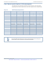
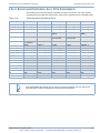
PCI-P0 DEVELOPMENT BACKPLANE
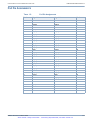
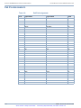
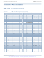
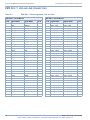
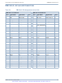
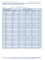
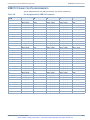
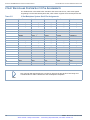
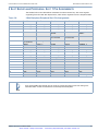
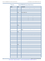
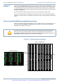
PCI-P0 BACKPLANE PIN ASSIGNMENTS
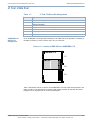
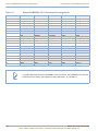
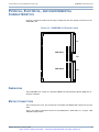
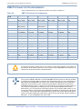
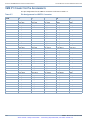
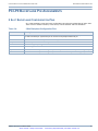
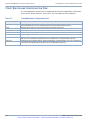
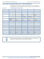
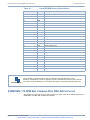
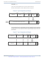
2 SLOT BACKPLANE CONFIGURATION PINS
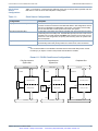
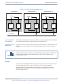
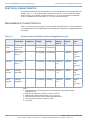
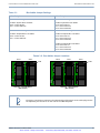
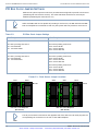
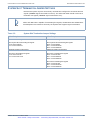
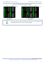
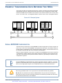
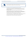
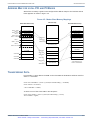
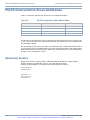
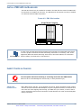
In a 2 slot backplane, each slot has 4 configuration pins that are independent of other slots.
These control: arbiter functions, clock source, line termination and bus arbitration.
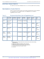
TABLE 3.4:
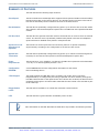
2 Slot Backplane Configuration Pins
Line
Description
Clock Source
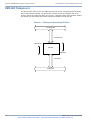
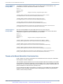
The card in System Slot 0 drives a clock out on pins D4 (CLK0) and C5 (CLK1). The peripheral card takes
its clock from its D4 pin. System Slot pin C5 connects to the peripheral slot’s D4 pin.
Reset
The Reset line is common on pin E4 and should only be driven from Slot 0.
Interrupts
The interrupt line INTA is common on pin E5.
+5 V Rail
The +5 V rail (pin A6) that goes to each P0 connector is isolated for each slot.
Ground
The GND signal is common across all slots.
Request Line
The REQ0 line on the System Slot 0 (pin C4) is driven by the REQ0 line on Peripheral Slot 1 (pin A4).
Grant Line
The GNT0 line on the System Slot 0 (pin A4) drives the GNT0 line on Peripheral Slot 1 (pin C4)
809524 REVISION D FEBRUARY 2009
Artisan Scientific - Quality Instrumentation ... Guaranteed | (888) 88-SOURCE | www.artisan-scientific.com
3-7