1
18114045_AE.book Page 62 Friday, July 4, 2003 10:31 AM
5
Reference information
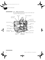
5.1.2 Modules and components
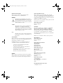
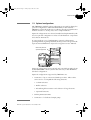
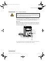
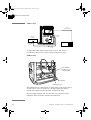
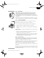
The following illustration shows the location of the modules and
components of the separation unit.
Buffer tray
Injection valve INV-907
Column holder
with column
On-line filter
Mixer M-925
with mixer chamber
Monitor UPC-900
Sample loop
50
0
µl
Pump P-900
UV lamp
UV flow cell
Optical unit
Mounting rack with
open handle
Base platform
W1 W2
Outlet to fraction collector
Flow restrictor
FR-902
62
Conductivity flow
cell with holder
ÄKTAFPLC System Manual 18-1140-45 Edition AE