1
phyCARD®-i.MX 6 [PCA-A-XL3-xxx]
17.2.3 LEDs
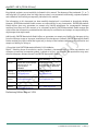
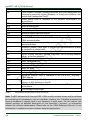
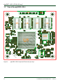
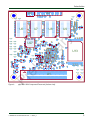
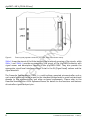
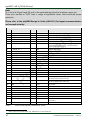
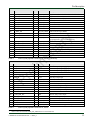
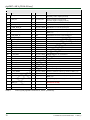
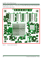
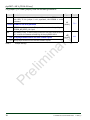
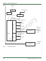
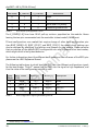
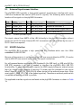
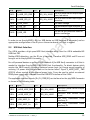
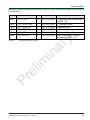
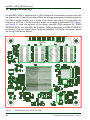
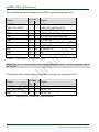
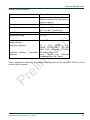
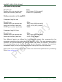
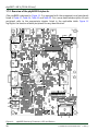
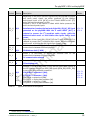
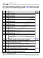
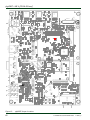
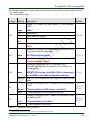
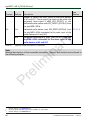
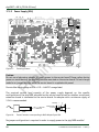
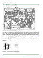
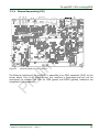
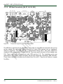
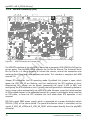
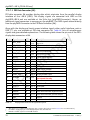
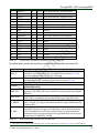
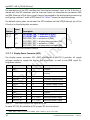
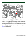
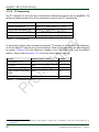
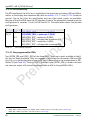
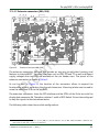
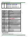
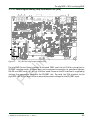
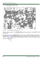
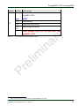
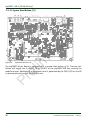
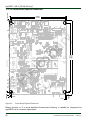
The phyBASE is populated with numerous LEDs to indicate the status of the various USBHost interfaces, as well as the different supply voltages. Figure 13 shows the location of
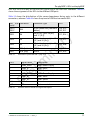
the LEDs. Their function is listed in the table below:
See
Section
Color
Description
D16
yellow USB1 amber led
D17
yellow USB2 amber led
D18
yellow USB3 amber led
D19
yellow USB4 amber led
D20
yellow USB5 amber led
D21
yellow USB6 amber led
D22
yellow USB7 amber led
D23
green
USB1 green led
D24
green
USB2 green led
D25
green
USB3 green led
D26
green
USB4 green led
D27
green
D28
green
D29
green
D30
red
D50
red
D49
red
Indicates presence of VBUS at the USB OTG interface
D37
green
5 V supply voltage for peripherals on the phyBASE
D38
green
supply voltage of the phyCARD
D39
green
3.3 V supply voltage for peripherals on the phyBASE
D40
green
3.3 V standby voltage of the phyBASE
D41
green
standby voltage of the phyCARD
D45
yellow SSI interface compliant with the AC'97 standard
USB5 green led
USB6 green led
USB7 green led
Active/Suspend status LED of the USB hub at U4
Pr
Hi-Speed indicator LED for USB hub's upstream port connection
speed
2
D46
green
D48
yellow user LED driven by the LED dimmer at U21
Table 30:
60
17.3.5
el
im
in
a
ry
LED
SSI interface compliant with the I S standard
17.3.6
17.3.2
17.3.8
phyBASE LEDs Descriptions
© PHYTEC Messtechnik GmbH 2014
L-800e_0