1
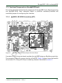
The phyCARD®-i.MX 6 on the phyBASE
17.2.1 Connectors and Pin Header
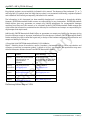
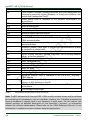
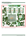
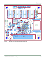
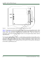
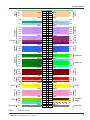
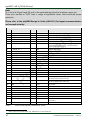
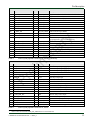
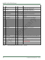
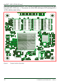
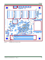
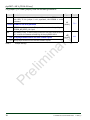
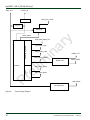
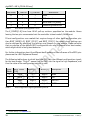
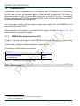
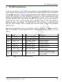
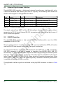
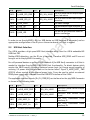
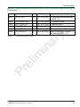
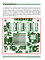
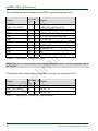
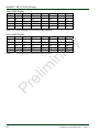
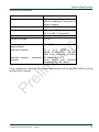
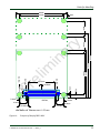
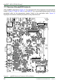
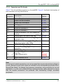
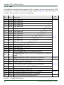
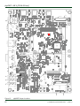
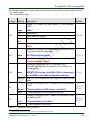
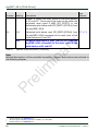
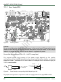
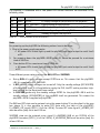
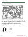
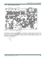
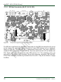
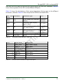
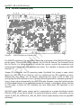
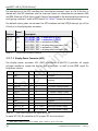
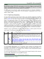
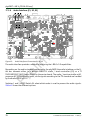
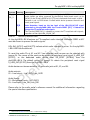
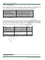
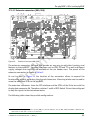
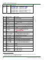
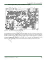
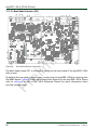
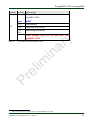
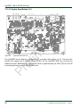
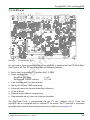
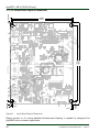
Table 27 lists all available connectors on the phyBASE. Figure 13 highlights the location of
each connector for easy identification.
X26
X27
X28
X29
X32
X33
P1
Table 27:
See
Section
17.3.8
17.3.8
17.3.8
17.3.7.1
17.3.5
17.3.12
17.3.12
17.3.4
ry
CPLD JTAG connector
Pr
X34
Stereo Microphone input connector
Stereo Line out connector
Stereo Line In connector
Display data connector
Dual USB Host connector
Extension connector 0
Extension connector 1
Ethernet connector, RJ45 with speed and
link led
Secure Digital/MultiMedia Card slot
phyCARD-Connector for mounting the
phyCARD-i.MX 6
Wall adapter input power jack to supply
main board power (+9 - +36 V)
USB On-The-Go connector
Display / Backlight supply voltage
connector
USB Host connector
el
im
X10
Description
in
a
Reference
Designator
X1
X2
X3
X6
X7
X8A
X9A
Serial Interface, DB-9F
17.3.13
17.3.1
17.3.2
17.3.6
17.3.7.2
17.3.5
for
internal
use only
17.3.3
phyBASE Connectors and Pin Headers
Note:
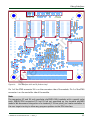
Ensure that all module connections are not to exceed their expressed maximum voltage or
current. Maximum signal input values are indicated in the corresponding controller User's
Manual/Data Sheets. As damage from improper connections varies according to use and
application, it is the user‘s responsibility to take appropriate safety measures to ensure
that the module connections are protected from overloading through connected
peripherals.
© PHYTEC Messtechnik GmbH 2014
L-800e_0
57