1
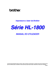
EN
User manual
Loop system LA-240
Introduction
The LA-240 Loop System provides a practical solution for hearing aid users to listen more
easily to their TV or Audio equipment via the “T” or “Loop” facility of their hearing aid.
With no direct connection between the user and a TV or Audio equipment the user is able to
move freely within the looped area and listen comfortably to a TV or audio equipment without
the distractions of normal listening.
The Loop System is used in conjunction with a hearing aid with a “T” or “Loop” function found
on many ‘behind the ear’ or ‘in the ear’ hearing aids. The Loop system picks up the sound
from a TV via a microphone or direct connection and feeds it to the amplifier. The sound is
then passed to a loop of wire around the listening area, which in turn transmits the sound
inductively, “magnetic sound waves”, to a hearing aid with the loop facility. The user may
then adjust the loop volume or tone to suit their own hearing preference without affecting
others.
The Loop System is supplied with a loop cable.
The loop cable is placed around a room that you want to listen in. The sound can be heard
anywhere inside the “looped” area and sometimes just outside the loop as well.
A loop pad (available as accessory) is an alternative to a loop cable and can be used to
create a localised or portable system to avoid interference with other systems or where
confidentiality is required.
Quick Setup
1. Check contents of package.
2. Place amplifier near TV or Audio equipment with or without stand.
3. Connect audio leads between TV or Audio system and Loop Amplifier.
4. Place loop cable around room and connect both ends of wire to the loop cable
connectors on the rear of the loop amplifier.
5. Plug the power supply unit lead into the amplifier. Connect the mains lead to the power
supply unit and place the mains plug into a convenient mains socket
6. Switch on TV / Audio equipment and Loop Amplifier.
7. Switch hearing aid to “T” or Loop function
8. Adjust loop amplifier volume/tone to suit listening level.
2
Important Safety Instructions
The manufacturer cannot be held responsible for damage which is caused by not using this
Loop System in compliance with these safety instructions.
IF IN ANY DOUBT SEEK EXPERT ADVICE
1. Read and follow these instructions taking note of any warnings.
2. Keep these instructions for future reference.
3. Do not use the system or accessories near water.
4. Do not expose the system or accessories to rain or any other source of moisture.
5. Should the amplifier require cleaning only do so with a dry cloth.
6. Ensure that there is enough room around the Loop Amplifier for ventilation purposes.
7. Do not cover the ventilation holes of the amplifier with anything.
8. Do not place the Loop Amplifier close to sources of heat, such as radiators.
9. Place all connecting and power leads such that they are not a hazard or where they
may become damaged.
10. Do not open casing of Loop Amplifier at any time; there are NO user serviceable parts.
11. Servicing must be referred to qualified service personnel.
CAUTION:
Ensure mains power is disconnected BEFORE any audio connections are made to the Loop
Amplifier. To completely disconnect the system from the mains, remove the mains plug
from the wall socket.
CAUTION:
The top surface of the amplifier may become hot when operating this system continuously.
Do not touch the top surface during use or block the ventilation holes.
3
Product Overview
VO
LU
An enhanced microprocessor controlled loop amplifier with outstanding sound quality designed to be used with modern audio and video products to transmit the sound direct to your
hearing aid. Your hearing aid must be switched to the “T” or Loop function to use the loop
system. You can also enjoy the benefits of the loop amplifier by simply plugging a set of headphones into the headphone socket on the rear of the amplifier.
For best results connect the amplifier directly to your TV or other sound source using the lead
kit supplied.
E
M
1
2
1) Volume Control 2) Tone Control 3) Loop level indicator
!
3
4 5 6 7 8
4) Microphone input select
5) Line input A select
6) Line Input B select
#
10) DC power socket 11) Loop cable connectors
12) Headphone socket 19) Microphone Input B
$
%
&(
13) Digital audio coaxial 14) Digital audio optical 15) Line Input B 7) Digital Audio input select
8) Power On/Standby
)
*+ ,
16) Line Input A
17) Microphone Priority
18) Microphone Input A
IMPORTANT
Always disconnect from mains supply before making any connections!
4
Setting Up
• The loop system is supplied ready for use with the following items
• Loop Amplifier with stand.
• Power Supply with lead and Mains lead with fitted plug.
• Digital audio optical TOSlink lead.
• Analogue audio lead kit : 1.2m phono – phono lead, SCART to RCA adaptor and
3.5mm stereo jack to RCA adaptor.
• 40m(130ft) Loop Cable and pack of 50 cable clips
• Guarantee Card
• User manual
Loop Amplifier
Place the amplifier in a convenient well ventilated area near to the TV or other audio source
such that all necessary connection leads can reach the relevant device. The optional stand
may be used to mount the amplifier vertically if required..
Place Loop Cable around listening area
Run the loop cable around the room starting and ending at the amplifier.
The cable may be tucked under the edge of the carpet, or fixed to either
a picture / dado rail or skirting board with the clips provided. Where the
cable passes a door or other obstacle, either fix the cable around the
frame or tuck under the carpet. The cable only has to go round the area
to be looped, it does not matter about going up and over doors/windows
or round fireplaces etc.
Excess loop wire may be cut off, provided a MINIMUM of 11 metres (35 feet) is left connected to
the amplifier. DO NOT leave spare cable coiled on the drum.
If using a Loop Pad
Place the loop pad (available as accessory) in a suitable position on the chair to be used for
listening, either on the chair back or under the seating area. Lay the connecting lead from the
Pad to the back of the Amplifier. Make sure that the connecting lead is kept out of the way to
prevent injury or obstruction.
5
Connect Loop Cable or Loop Pad to the amplifier
When the loop cable connector (11) buttons are pushed in a hole will
appear. Push the bare wire into the hole. Ensure that only the bare
wire and not the plastic insulation goes into the hole, then release
the button to lock the cable in place.
Connect Audio Inputs from TV or other Audio Source to Loop Amplifier
Direct audio connections
This is the preferred method of connecting your amplifier to TV and other audio products. It
will deliver the clearest sound to you without background noise affecting the clarity.
This amplifier is fitted with digital and analogue audio inputs.
Digital Optical TOSlink and Coaxial outputs are found on most current TVs and Audio equipment.
These connections (13) & (14) will provide the clearest sound input to your system.
Analogue audio connections use the red/white phono audio connectors (15) & (16) on the loop
amplifier. Analogue audio is widely found on all types of equipment.
Up to 3 pieces of equipment may be directly connected to the loop amplifier at any one time.
One digital using either TOSlink or Coaxial but NOT both at the same time and one or two
pieces of equipment with analogue audio output.
If the TV or other sound source does not have a set of phono connectors then use the SCART
or jack adaptors accordingly to connect the equipment. If you use the jack adaptor you may
find that when plugging into a headphone socket on your TV etc., this turns off the internal
speaker. On some TVs there may be a switch that allows the TV speaker to be left on.
Microphones
If a direct connection is not possible then a microphone can be used to pick up the sound
from a TV or other loudspeaker. Microphones can also be used for someone to speak directly
into the loop system so they can speak directly to the hearing aid user while they listen to
TV. A microphone can be used at the same time as the line inputs to monitor environmental
sounds such as a doorbell or telephone bell.
A microphone can also be used in either a classroom or other public speaking situations.
One or two microphones can be used at the same time using sockets (18) & (19).
A priority function also exists when using a microphone in channel B (19) to override sounds
from any other input to the loop amplifier.
6
Power
Plug the power supply lead into the socket (10) on the rear of the amplifier. Connect the mains
lead to the power supply and then plug into a mains outlet. Switch on the power at the outlet.
This amplifier may also be used with DC power supplies directly connected to the amplifier
such as those found in buses and coaches.
Operation
When connecting power for the first time to your amplifier the power button (8) will illuminate
blue and the amplifier will be “On”. This is normal operation and is useful where remote
switching of the system is required such as in buses and coaches.
Pressing the power button will change the colour to red and the amplifier will be in the standby mode which uses low power and no signal will be passed to the loop. In order to remove
all power from the unit the power supply must be disconnected from the amplifier and the
mains outlet.
Press the button power again and it will light up blue. The system is now ready for use.
• Set the television or other audio equipment to the normal listening level for other members of your household.
• Select the sound source required from the buttons (4) - (7).
• Set the volume control to minimum.
• Set the tone control to the normal position (12 o’clock).
• Switch your hearing aid to the ‘T’ or loop function.
• Adjust the volume and tone to suit your listening.
Pressing the power button will turn the amplifier off and the light will go red. The next time
the power is turned on the volume, tone and source selections from the previous session will
be restored.
Volume control (1)
Use to adjust the volume of the signal received by the hearing aid. As the signal increases the
blue light will travel around the control indicating the volume in use.
Tone control (2)
Use to vary the tone of the signal. Turned in the clockwise direction the higher frequencies will
be emphasised and in the anti-clockwise direction the lower frequencies will be emphasised.
7
As the tone control is moved the blue light will travel around the control indicating the tone
position in use.
Loop level Indicator (3)
This indicates that a signal is being transmitted by the loop cable. It flickers with a low volume
and remains steady with louder volumes. Testing the system can be done by speaking into
a microphone and seeing the light flash, this will indicate that a signal is flowing round the
cable.
Sound source selections (4-7)
Pressing one of these buttons will select the sound source connected to the amplifier in
the corresponding sockets 13-19 on the rear of the amplifier. One or more of these can be
selected at any one time. When the channel is selected a blue light will show in the button.
Pressing again and the light will go out showing that channel is off.
Microphone
(4)
Selecting this will allow sound from microphones connected to sockets (18) and/or (19). If
a microphone is plugged into socket B (19) then if the priority button (17) is pushed in any
sound received by this microphone will override all the other sounds connected to the loop
system. This can be useful when used to monitor a doorbell or telephone bell or if a partner
wants to talk to the hearing aid wearer through the loop.
Analogue Line Input A
(5) and Analogue Line Input B
(6)
Wählt die jeweiligen eingehenden Signale von Kanal A (16) oder B (15) an. Dient zur Auswahl
von z. B. Fernseher oder DVD-Player, sodass die Auswahl des jeweiligen Gerätes bequem von
der Vorderseite des Verstärkers getätigt werden kann. Es können beide Kanäle gleichzeitig
ausgewählt werden.
Digital Audio
(7)
Allows the selection of the line input signals from channel A (16) or B (15). Useful to connect
to a TV and DVD player so that either may be simply selected from the front panel. Either or
both channels may be selected simultaneously.
Headphone socket
(12)
The Headphone socket may be used with headphones that have a stereo 3.5mm plug fitted.
This may be used by a non-hearing aid user to receive amplified sound. It can also be used to
test that the loop system is set up correctly. Headphones used in this way will not affect the
performance of the loop system for hearing aid users. The headphone socket may be used
without a loop cable being connected but the loop level indicator will not show.
8
Remote Control
The remote control allows the user to operate all the front panel controls of the amplifier previously
described with the addition of a mute function for the volume.
9
Problems and Cures
Symptom
No sound
Possible cause and remedy
• Re check all connections.
• Amplifier not switched on. Switch on at mains socket.
Press mains switch. Check blue light is on.
• Microphone or audio source not connected or
selected.
• Hearing aid not on the ”T” or loop program.
Low sound
Distorted sound
•
•
•
•
Microphone too far from sound.
Loop cable wired incorrectly.
Volume control set too low. Increase volume.
TV or audio volume set too low. Increase volume.
• Volume control set too high. Loop level indicator
showing permanently. Decrease volume.
• TV/ Audio volume set too high.
• Move microphone away from loud speaker.
• Microphone Plug/lead damaged.
Background noise
(hum or buzz)
• If noise remains when loop amplifier is turned off but
hearing aid is still on loop program this interference
caused by other equipment such as fluorescent lights
or dimmer switches. With the loop amplifier turned
off and the hearing aid still on the loop programs
turn items off and on until the interference can be
identified.
• If noise stops when the loop amplifier is turned off
there may be a fault in th esystem or microphjione
lead or noise is being picked up by the microphone.
10
Specifications
Power Supply
Controls
Input connections
•
•
•
•
•
•
18V 1.5A Power Supply
Rotary Volume Control
Rotary Tone control
On/Off power switch
Source selector switches
Priority switch
• Digital Audio TOSlink/Coaxial
• 2 x Microphone inputs. 3.5mm mono jack plug. DC
powered 5V for electret microphones
• 2x Aux In Left/Right line inputs. Phono/RCA sockets. For
direct connection to a TV sound output or other audio
source via SCART or other suitable socket.
Output connections
• Push grip connectors for loop cable or loop pad (Labelled:
Loop Cable). Loop will give full output with loop resistance
between 0.5 and 1.5 Ohms.3,5mm
• 3.5mm stereo jack for headphones (Phones) 8-60 Ohms
Loop output
• 3.0A output current @ 100-5KHz.
Meets BS EN60118-4:2006 for a loop not exceeding
6.5m (20ft) in width . Suitbale for areas up to 70m2
Loop cable
• Single turn loop cable. System supplied with 40m (130ft)
24/0.2mm (0.75mm2) single core PVC insulated cable.
Min cable length 11m = 0.5 Ohms
Indicators
• Blue/Red LEDs
Humantechnik GmbH and Sarabec Ltd declare that the LA-240 complies with all relevant
EU directives. The full EU declaration of conformance for the LA-240 is available on
www.humantechnik.com and www.audioropa.com
11
Humantechnik Service-Partner
D
Germany
CH
Switzerland
F/B
France
Belgium
AU
Australia
IL
Israel
Humantechnik GmbH
Im Wörth 25
D-79576 Weil am Rhein
Tel.: +49 (0) 76 21/ 9 56 89-0
Fax: +49 (0) 76 21/ 9 56 89-70
E-mail:[email protected]
Humantechnik GHL AG
Rastatterstrasse 9
CH-4057 Basel
Tel.: +41 (0) 61/ 6 93 22 60
Fax: +41 (0) 61/ 6 93 22 61
E-mail:[email protected]
SMS
Audio Electronique Sàrl
173 rue du Général de Gaulle
F-68440 Habsheim
Tel.: +33 (0) 3 89/ 44 14 00
Fax: +33 (0) 3 89/ 44 62 13
E-mail:[email protected]
Group Technologies
86 Derby Street
3044 Pascoe Vale, Victoria
Tel.: +61 393 549 133
Fax: +61 393 549 233
[email protected]
Steiner Hearing Instrum. Ltd
Abbas 10 St.
IL - 31094 Haifa
Tel.: +972 - 4 - 852 1514
Fax: +972 - 4 - 855 389 38
E-mail:[email protected]
For other service-partners
in Europe please contact:
Humantechnik Germany
Tel.: +49 (0) 76 21/ 9 56 89-0
Fax:+49 (0) 76 21/ 9 56 89-70
Internet: www.humantechnik.com
E-mail: [email protected]
RM422100 · 0515