1
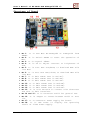
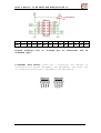
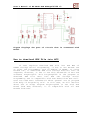
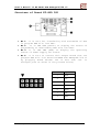
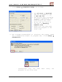
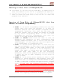
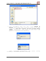
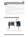
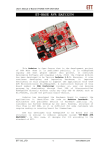
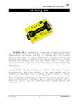
User’s Manual of ET-BASE AVR ATmega64/128 r3
ET-BASE AVR ATmega64/128 r3
ET-BASE
AVR
ATmega64/128
r3
is
AVR
Board
Microcontroller from ATMEL that uses 64Pin MCU No.ATmega64
and No.ATmega128. It mainly emphasizes on using resources of
MCU on this Board ET-BASE AVR ATmega64/128 r3. I/O Pins are
externally connected to be Port PA, PB, PC, PD, PE, PF and
Port ET-CLCD; so, it is more convenient to connect, and
including Port for downloading program. Moreover, it adds
Circuit Line Driver RS-232 to increase the capability of RS232 Serial Port Communication easier and more convenient.
Features of Board
•
•
•
•
•
•
•
Use 8Bit AVR MCU No.ATmega64, ATmega128 from ATMEL and
use Signal Clock Generator as XTAL 16MHz. Moreover,
there are other outstanding features of MCU as follows;
Has 64Kbyte Flash Memory for ATmega64, 128Kbyte
Flash Memory for ATmega128 and 4Kbytes RAM
Has 2Kbyte EEPROM for ATmega64 and 4Kbyte EEPROM for
ATmega128; can be re-written more than 100,000 times
Has a maximum of 53 I/O Pins
Has
1-Channel
SPI,
1-Channel
I2C,
2-Channel
Programmable Serial USARTs
Has 8-Channel 10-Bit ADC
Has 2-Channel 8-Bit Timers/Counters, 2-Channel 16Bit Timers/Counters, 2-Channel 8-Bit PWM, Watchdog
Timer, Real Time Counter
Has 6 of 10PIN I/O PORTs: PA,PB,PC,PD,PE,PF
Has Port ISP LOAD for programming MCU (has to use with
ET-AVR ISP of other ISP Programmers that has the same
pin arrangement)
Has Circuit Line Driver 2-Channel for RS232 Serial Port
Communication; one channel is connected with Signal
PE0(RXD0) and PE1(TXD0); and other one is connected with
PD2(RXD1) and PD3(TXD1); so, user can connect with RS232
easily.
Has circuit to connect with Character LCD Display (ETCLCD) and VR to adjust contrast or brightness of LCD;
circuit is connected with 4Bit Interface LCD.
Has Circuit +5V/2A Regulate to be Power Supply for
Circuit LCD Display and I/O Devices that are compatible
with +5V Power Supply, including red LED to display the
operating status.
Be small PCB Size: 8 x 6 cm.
ETT CO.,LTD
-1-
www.etteam.com
User’s Manual of ET-BASE AVR ATmega64/128 r3
Structure of Board
•
•
•
•
•
•
•
•
•
•
•
•
•
•
•
•
•
No.1: It is AVR MCU No.ATmega64 or ATmega128 from
ATMEL.
No.2: It is Switch RESET to reset the operation of
MCU.
No.3: It is Crystal 16MHz.
No.4: It is VR to adjust contrast or brightness of
LCD.
No.5: It is Port AVR ISP(6PIN) to download HEX File
into MCU.
No.6: It is Port AVR ISP(10PIN) to download HEX File
into MCU.
No.7: It is 8Bit PORTC that is PC0-PC7.
No.8: It is 8Bit PORTA that is PA0-PA7.
No.9: It is 8Bit PORTF that is PF0-PF7.
No.10: It is 8Bit PORTE that is PE0-PE7.
No.11: It is 8Bit PORTB that is PB0-PB7.
No.12: It is 8Bit PORTD that is PD0-PD7.
No.13: It is Port ET-CLCD to connect with Character
LCD that is 4Bit Interface.
No.14 and 15: It is Connector RS232 for general use.
No.16: It is Jumper to choose between RS232 or Port
I/O.
No.17: It is Connector Power Supply for board.
No.18: It is LED Power to display the operating
result of +5VDC Power Supply.
ETT CO.,LTD
-2-
www.etteam.com
User’s Manual of ET-BASE AVR ATmega64/128 r3
Connectors
It has designed and arranged Connectors of Port I/O
from MCU through 6 of Connectors IDC-Header 10PIN (2x5) that
are PA, PB, PC, PD, PE, and PF respectively. Connectors in
each set consist of Signal I/Os that are directly connected
from Pin of MCU. The connecting points that are used to
interface with external signal are listed below;
• Connector Power Supply for board
• Connector 8Bit PORTA that is PA0-PA7
• Connector 8Bit PORTB that is PB0-PB7
• Connector 8Bit PORTC that is PC0-PC7
• Connector 8Bit PORTD that is PD0-PD7
• Connector 8Bit PORTE that is PE0-PE7
• Connector 8Bit PORTF that is PF0-PF7
• Connector ET-CLCD to connect with Character LCD
• 2-Channel Connector RS232; one channel is connected
with PE0(RXD0) and PE1(TXD0); and other one is
connected with PD2(RXD1) and PD3(TXD1); so, user can
connect with RS232 easily.
• Connector AVR ISP to download HEX File into MCU
8BIT PORT PA
8BIT PORT PB
ETT CO.,LTD
-3-
www.etteam.com
User’s Manual of ET-BASE AVR ATmega64/128 r3
8BIT PORT PC
8BIT PORT PD
8BIT PORT PE
8BIT PORT PF
ETT CO.,LTD
-4-
www.etteam.com
User’s Manual of ET-BASE AVR ATmega64/128 r3
Port AVR ISP
Figures display circuit to connect with AVR ISP.
Port ET-CLCD: It is used with Character LED as 4Bit
Interface and it uses signals from Port PG and PD(PD7) to
connect with LCD. It connects Cable from Connector of Port
LCD to LCD Display; in this case, it uses the pin names to
be the reference point; so, all 14 Cables must be agreed
with all 14 pin names.
ETT CO.,LTD
-5-
www.etteam.com
User’s Manual of ET-BASE AVR ATmega64/128 r3
1
2
3
GND +VCC VO
4
5
6
RS RW EN
Figure displays
standard type.
how
to
7
D0
8
D1
arrange
9
D2
pin
10
D3
of
11
D4
12
D5
Character
13
D6
14
D7
LCD
as
2-Channel Port RS232: There are 2 channels; one channel is
connected with Signal PE0(RXD0) and PE1(TXD0); and other one
is connected with Signal PD2(RXD1) and PD3(TXD1).
ETT CO.,LTD
-6-
www.etteam.com
User’s Manual of ET-BASE AVR ATmega64/128 r3
Figure displays the part of circuit that is connected with
RS232.
How to download HEX File into MCU
If user requires download HEX File into AVR MCU of
ATMEL through Serial Programming, it has to use ET-AVR ISP
or other ISP Programmers such as AVRISP of AMTEL. If using
ET-AVR ISP, it downloads HEX File through Parallel Port of
computer; moreover, it has to use with ET-CAP10P of ETT and
Software PonyProg200. This PonyProg2000 is the program to
download HEX File data into AVR CPU through Serial
Programming and is compatible with AVR Board from ETT well.
User can read more information about general use of program
from Help of Program by self. In this case, we will mention
about how to setup Program PonyProg2000 to use with AVR
Board from ETT; moreover, it is compatible with all AVR
Boards from ETT.
ETT CO.,LTD
-7-
www.etteam.com
User’s Manual of ET-BASE AVR ATmega64/128 r3
Structure of Board ET-AVR ISP
•
•
•
•
No.1: It is Port for interfacing with ET-CAP10P of ETT
to program HEX File into MCU.
No.2: It is LED PGM (Green) to display the status of
programming or downloading HEX File into MCU.
No.3: It is LED PWR (Red) to display the operating
status of Power Supply for board.
No.4: It is Port to connect with Target Board that can
program HEX File into board ET-BASE AVR ATmega64/128 r3
by plugging Board ET-AVR ISP in Port AVR ISP. It
arranges pins as shown in the picture below;
Pin Position
1
2
3
4,6,8,10
5
7
9
ETT CO.,LTD
-8-
Signal Name
MOSI
VCC
Unused
GND
RESET
SCK
MISO
www.etteam.com
User’s Manual of ET-BASE AVR ATmega64/128 r3
How to connect devices to program HEX File
If user requires programming HEX File Code into AVR
MCU,
it
has
to
use
with
ET-CAP10PIN
and
Program
PonyProg2000. It connects ET-CAP10PIN with Printer Port;
sets Jumper for using with Program PonyProg2000; connects
Cable Download at Connector AVR ISP Download of board; and
then supplies power into the board completely. If there is
any external device is connected with Port PB, user has to
remove it from the port first. The connection’s feature is
shown in the picture below;
(Left) ET-CAP10P V2.0
(Right) ET-CAP10P V1.0
Picture shows how to set Jumper and interface Cable Download
of ET-CAP10P for using with AVR.
ETT CO.,LTD
-9-
www.etteam.com
User’s Manual of ET-BASE AVR ATmega64/128 r3
Picture shows how to connect ET-AVR ISP with ET-BASE AVR
ATmega64/128 r3 by connecting both boards together. Please
look at position of PIN 1, it must agree.
How to program Board ET-BASE AVR ATmega64/128 r3
by Program PonyProg2000
Program PonyProg2000 is the program to download HEX
File Data into AVR CPU through Serial Programming and it is
compatible with AVR Board from ETT well. User can read more
information about general use of program from Help of
Program by self. In this case, we will mention about how to
setup Program PonyProg2000 to use with AVR Board from ETT;
moreover, it is compatible with all AVR Boards from ETT.
Please be careful in using AVR CPU No.ATmega64/128,
there are many Fuse Bits internal structure of ATmega64/128
that are used to set conditional operations of CPU. Some
Fuse Bits have effect on Serial Programming Download; if
user sets these Fuse Bits wrongly, it is unable to program
any CPU by Serial Programming any more. In this case, user
needs to edit these Fuse Bits by Parallel Programmer
correctly first.
If using Program PonyProg2000 to program AVR CPU that
is used with ETT Board, it needs to set Option of program as
follows;
ETT CO.,LTD
-10-
www.etteam.com
User’s Manual of ET-BASE AVR ATmega64/128 r3
1. Click Setup → Interface Setup… as follows;
- Set I/O Port as Parallel
and the Programming type
as Avr ISP I/O
- Set Printer Port according
to actual connection; for
example, LPT1 if using
with Printer Port LPT1
- Do not set any value in
the part of Polarity
Control Line
- Setup only one time when
using the program in the
first time
2. Set Program PonyProg2000 to calculate the proper speed
for transmitting signal to program CPU, click Setup →
Calibration.
-
ETT CO.,LTD
Calibration only one time
program in the first time
-11-
when
using
the
www.etteam.com
User’s Manual of ET-BASE AVR ATmega64/128 r3
3. Set CPU number, click Device → AVR Micro →
Atmega64
or ATmega128
4. Click Command → Security and Configuration Bits. If it
is other AVR numbers, user can set the operation of Fuse
Bit as required and user can read more information of
the Fuse Bits from Data Sheet of CPU by self. If using
with ATmega64/128, please be careful in setting Fuse
Bits correctly, otherwise user cannot program any CPU
through Serial Programming any more. After set values as
shown in the picture completely, click Button Write.
(This process has been done only one time and user can
skip this process when entering later. If using Board
ET-BASE AVR ATmega64/128 r3, it is unnecessary to do
this process again because ETT has already set the
values, except user requires changing the value.)
Picture displays
No.ATmega64/128.
ETT CO.,LTD
how
to
set
-12-
Fuse
Bit
to
use
with
CPU
www.etteam.com
User’s Manual of ET-BASE AVR ATmega64/128 r3
Meaning of Fuse Bits of ATmega64/128
If ticked [√] in front of any Fuse Bit, it means that it
sets the Fuse Bit to be “0” or it programs the Fuse Bit.
If did not tick [√] in front of any Fuse Bit, it means
that it sets the Fuse Bit to be “1” or it does not
program thee Fuse Bit.
Meaning of Fuse Bits of ATmega64/128 that has
effect on Serial Programming
•
•
•
•
SPIEN: It is Serial Programming Enable Bit and user
always sets this Fuse Bit because it is able to
download program into CPU through In-System Serial
Programming. Normally, this Fuse Bit has been set
from the factory and it cannot be erased or edited
by any Serial Programming Mode. If CPU has been
programmed by Parallel Programming, user does not
forget to set and program this Fuse Bit.
OCDEN and JTAGEN: Both bits are used in case of
debugging the operation of MCU, programming data
through JRTAG Interface, and it has to use with AVR
JTAG Debugger. If user does not use this operation,
it is unnecessary to choose both bits.
CKOPT: It is Oscillator Option Bit. If this Fuse Bit
has been programmed, it sets CPU to run at Frequency
16MHz; on the other hand, if this Fuse Bit has not
been programmed, it sets CPU to run at Frequency not
higher than 8MHz. If using with the standard Board
from ETT that uses XTAL to be the Frequency
Generator, user should program this Fuse Bit because
it makes CPU run at XTAL frequency in the range of
1.0MHz–16.0MHz.
CKSEL3…0: It is Select Clock Source Bit that is used
together to choose Generator and frequency range for
using with CPU. If using with standard Board of ETT,
it has to set the value as External Crystal 1.0MHz16.0MHz, otherwise it makes the operation of program
error. If user sets the Frequency Generator wrongly;
for example, if user sets the value as External
Clock or External RC Oscillator, it makes CPU cannot
work because it has not been connected with external
Signal Clock. So, it is unable to program CPU
through Serial Programming any more. User has to
edit Fuse Bit of the CPU correctly and it needs to
choose the Frequency Generator as External Crystal.
ETT CO.,LTD
-13-
www.etteam.com
User’s Manual of ET-BASE AVR ATmega64/128 r3
Clock Generator of AVR Atmega128
External Crystal/Ceramic Resonator
External Low Frequency Crystal
External RC Oscillator
Calibrated Internal RC Oscillator
External Clock
Setting Fuse Bit of CKSEL[3-0]
(0=Program,1=Un-Program)
1111-1010
1001
1000-0101
0100-0001
0000
Table shows how to choose Frequency Generator from Fuse Bit
CKSEL [3…0].
NOTE:
- Value “1”: It means that it does not program the Fuse Bit
and there is no any tick sign [√] in front of the Fuse
Bit.
- Value “0”: It means that it programs the Fuse Bit and
- Should program the Fuse Bit of CKOPT to run at the
Frequency 1.0MHz-16.00MHz
- Not allowed to program Fuse Bit of CKSEL[3..0] because it
makes the operation error. For example, if user programs
all Fuse Bits of CKSEL[3..0] as 0; after Program
PnonyProg2000 wrote this Fuse Bit into CPU completely, it
is unable to use CPU with ETT Board anymore; moreover, it
is unable to program and edit any new Fuse Bit into CPU
through Serial Programming because CPU is unable to work.
Remember, if user has programmed all Fuse Bit of
CKSEL[3..0] as “0”, it commands CPU to run with frequency
of External Clock, so it makes the Frequency Generator of
External Crystal stop running; in this case, CPU waits to
receive the External Clock only. However, ETT Board only
uses
Signal
Clock
from
Circuit
Crystal
(External
Crystal); so, if CPU cannot start running, it is unable
to program or edit any Fuse Bit for CPU correctly through
Serial Programming. It has to edit Fuse Bit of the CPU by
Parallel Programmer first and user can use CPU with
Serial Programming again.
- Set the Fuse Bit position of Lock[2…1] as required.
5. Click Command → Program Option as follows;
ETT CO.,LTD
-14-
www.etteam.com
User’s Manual of ET-BASE AVR ATmega64/128 r3
file to program into CPU, click File → Open
Program (FLASH) File… → specify name and location of
HEX File to program completely.
6. Open
ETT CO.,LTD
-15-
www.etteam.com
User’s Manual of ET-BASE AVR ATmega64/128 r3
programming data into CPU, click Command →
Program; and program start running as chosen in the step
5 that are Load File → Erase → Write Program memory
(FLASH) respectively. User needs to wait until the
operation of program runs completely.
7. Start
After programmed successfully, CPU
according to the downloaded data instantly.
ETT CO.,LTD
-16-
starts
running
www.etteam.com
User’s Manual of ET-BASE AVR ATmega64/128 r3
How to initially check if be unable to download
program
the
If any error occurred while programming, please check
problem as follows;
Read manual of board and learn how to download Program
AVR by PonyProg2000 throughout
Check the Cables’ connection; if downloading program
through PonyProg2000, it has to use with Cable Download
“ET-CAP10PIN” of ETT and then sets Jumper to be
“PonyProg” correctly (see more detailed in Page 9).
Check Power Supply of board
Check
setting
values
of
program
to
download
PonyProg2000
Check whether signal from PORT-PB of CPU is connected
with external devices while downloading or not. For
example, Signal from Port PB is connected with LED or
other circuits while downloading data.
How to use with other Programmers
Example of using with AVRISP mkll from ATMEL
ETT CO.,LTD
-17-
www.etteam.com
User’s Manual of ET-BASE AVR ATmega64/128 r3
Example of using with ET-AVR ISP USB V1.0 from ATMEL
Example of using with ET-AVR ISP mkll from ETT
ETT CO.,LTD
-18-
www.etteam.com
1
2
3
4
5
6
+5V
VR1
10k
+5V
H1
CONTRAST
1
3
5
2
4
6
0R
C3
10uF
C4
100n
PE0
C6
100n
C5
100n
AVR ISP
+5V
AVR ISP
2
V+
C1-
4
C2+
5
C2-
C9
100n
C10
C1+
3
100n
C11
14
7
13
8
T1IN
T1OUT
T2IN
T2OUT
R1OUT R1IN
R2OUT R2IN
1
2
3
JP4
18
PG3(TOSC2)
PG4
19
PG4(TOSC1)
PG2
PG1
PG0
43
34
33
1
PG2(ALE)
PG1(RD)
PG0(WR)
PEN
R3
10k
1
4
RS232-CH0
+5V
J2
1
RXD1 2
TXD1 3
4
RS232
PORT
H10
+5V
H11
+5V
1
2
3
4
PF7
PF6
PF5
PF4
PF3
PF2
PF1
PF0
RS232-CH1
1
2
3
4
54
55
56
57
58
59
60
61
PF7(ADC7/TDI)
PF6(ADC6/TDO)
PF5(ADC5/TMS)
PF4(ADC4/TCK)
PF3(ADC3)
PF2(ADC2)
PF1(ADC1)
PF0(ADC0)
ATMEGA128
PA7
PA6
PA5
PA4
PA3
PA2
PA1
PA0
(OC2/OC1C)PB7
(OC1B)PB6
(OC1A)PB5
(OC0)PB4
(MISO)PB3
(MOSI)PB2
(SCK)PB1
(SS)PB0
17
16
15
14
13
12
11
10
PB7
PB6
PB5
PB4
PB3
PB2
PB1
PB0
(A15)PC7
(A14)PC6
(A13)PC5
(A12)PC4
(A11)PC3
(A10)PC2
(A9)PC1
(A8)PC0
42
41
40
39
38
37
36
35
PC7
PC6
PC5
PC4
PC3
PC2
PC1
PC0
(T2)PD7
(T1)PD6
(XCK1)PD5
(ICP1)PD4
(TXD1/INT3)PD3
(RXD1/INT2)PD2
(SDA/INT1)PD1
(SCL/INT0)PD0
32
31
30
29
28
27
26
25
PD7
PD6
PD5
PD4
PD3
PD2
PD1
PD0
(ICP3/INT7)PE7
(T3/INT6)PE6
(OC3C/INT5)PE5
(OC3B/INT4)PE4
(OC3A/AIN1)PE3
(XCK0/AIN0)PE2
(TXD0/PDO)PE1
(RXD0/PDI)PE0
9
8
7
6
5
4
3
2
PE7
PE6
PE5
PE4
PE3
PE2
PE1
PE0
1
3
5
7
9
2
4
6
8
10
PA1
PA3
PA5
PA7
2
4
6
8
10
PB1
PB3
PB5
PB7
2
4
6
8
10
PC1
PC3
PC5
PC7
H2
PB0
PB2
PB4
PB6
1
3
5
7
9
PB0-PB7
H3
PC0
PC2
PC4
PC6
1
3
5
7
9
D1
PC0-PC7
H4
1
PD0
PD2-H4 3
5
PD4
7
PD6
2
PD1
4 PD3-H4
6
PD5
8
PD7
10
9
PD0-PD7
H5
PE0-H5 1
3
PE2
5
PE4
7
PE6
2 PE1-H5
4
PE3
6
PE5
8
PE7
10
9
S1G
1
C14
100n
2
1
VIN
4
CONT
C
PE0-PE7
H6
PF0
PF2
PF4
PF6
1
3
5
7
9
2
4
6
8
10
PF1
PF3
PF5
PF7
LOGO ETT
U3
KIA278R05
C13
100uF/25V
B
PF0-PF7
VO
2
GND
3
D
+5V
C15
470uF/16V
+
3
2
1
A
PA0-PA7
J3
6-12VDC
+
D
PG3
RXD0 2
TXD0 3
PD2-H4
PD3-H4
1
2
3
JP3
PD3
PE0-H5
1
2
3
JP2
PE0
PE1-H5
PE1
1
2
3
JP1
VCC
VCC
GND
GND
J1
R4
330R
PD2
R8
0R
C
R7
0R
AREF
AVCC
GND
+5V
ICL3232
R5
330R
C12
100n
U2P
6
V-
11
10
12
9
100n
+5V
100n
16
1
GND
C8
VCC
U2
15
B
C7
100n
52
21
22
53
XTAL1
44
45
46
47
48
49
50
51
+5V
XTAL2
(AD7)PA7
(AD6)PA6
(AD5)PA5
(AD4)PA4
(AD3)PA3
(AD2)PA2
(AD1)PA1
(AD0)PA0
+5V
23
Y1
C2 22pF
24
16MHz
62
64
63
+5V
H9
PE1
PB1
RST
RESET
C1 22pF
+5V
RST
PB1
PE1
bead
+5V
2
4
6
8
10
R2
L1
+5V
+5V
H8
1
3
5
7
9
20
+5V
SW1
RESET
PG0
PG2
ET-CLCD
PE0
U1
RST
3
4
GND
VO
RW
D0
D2
D4
D6
+5V
R1
10k
1
2
PG1
PG3
2
4
6
8
10
12
14
+
+V
RS
EN
D1
D3
D5
D7
PG4
PD7
A
1
3
5
7
9
11
13
+5V
PA0
PA2
PA4
PA6
H7
R6
560R
C16
100n
3
LED1
PWR
4
Sheet Title:
Project Title: ET-BASE AVR MEGA128
Drawn By: ETT CO., LTD.
Date: 23/9/2553 15:25:44
5
Size: A4
REV: 3
Sheet: 1/1
6