1
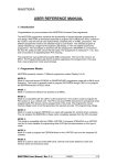
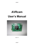
MR-Servo8
User Manual
CONTENTS
PART 1 : MR-Servo8
1. Introduction
2. Features
3. Control
PART 2 : CPU Board
1. Placement Diagram (Silkscreen)
2. Circuit Diagram
3. Parts List
PART 3 : Software Tools
1. AVR Development Program Installation
2. How to use WinAVR GCC
3. How to use PonyProg2000
PART 4 : Compile and Download
1. Compile and Download
PART 5 : Source Codes
PART 1 : MR-Servo8
1. Introduction
MR-Servo8 is a small pre-assembled R/C(Radio Control) servomotor controller, which has 16 R/C servo
connectable I/O pins. The MR-Servo8 can control up to 8 R/C servos at the same time. The MR-Servo8
uses an ATmega8(Atmel AVR series) CPU chip as a controller. The ATmega8 has a 4K bytes In-System
Programmable Flash memory, 128 bytes SRAM, 256 bytes EEPROM and many other peripherals. The user
can download a program to the board without a ROM Writer using the ISP function. A free C-compiler
(WinAVR) is available.
2. Features
• ATmega8 (Atmel AVR series, 16MHz X-tal(16 MIPS) but internal 8MHz RC Oscillator setting is required
for the RC Servo Source Example. Refer to “Security Bit Settings for ATMega Family.pdf” for the
setting. )
• 8K bytes ISP flash, 1K bytes SRAM, 512 bytes EEPROM, three Timers, ADC 8ch, UART
• 16 R/C servos connectable
(16 I/O port pins)
• Controls up to 8 R/C servomotors at the same time
• C source code
• Free Windows C compiler(WinAVR AVR GCC)
• ISP downloader(Optional)
• On board piezo Buzzer
3. Control
The board has sixteen I/O port pins and can control 8 servomotors at the same time. The ATmega8 CPU
has three internal counters. The board generates up to eight periodic pulses using the timers. The periodic
pulses control R/C servomotors.
PART 2 : BOARD
1. Placement Diagram(Silkscreen)
Fig 1.1 ATmega8 Servomotor control board silkscreen.
5
4
3
2
1
2. Circuit Diagram
VCC
VCC
U1
D
VCC
VCC
PD0(RXD)
PD1(TXD)
PD2(INT0)
PD3(INT1)
PD4(TO)
PD5(T1)
PD6(AIN0)
PD7(AIN1)
4
5
R4
10K
18
20
21
/RESET
C
S3
+
Tack
30
31
32
1
2
9
10
11
29
3
6
C3
1uF
PC5(ADC5/SCL)
PD0(RXD)
PC4(ADC4/SDA)
PD1(TXD)
PC3(ADC3)
PD2(INT0)
PC2(ADC2)
PD3(INT1)
PC1(ADC1)
PD4(TO/XCK)
PC0(ADC0)
PD5(T1)
PD6(AIN0)
PD7(AIN1) PB6(XTAL1/TOST1)
28
27
26
25
24
23
VCC
GND
8
PB7(XTAL2/TOST2)
17
16
15
14
13
12
GND
VCC
19
22
R1
470
C1 20pF
7
PB5(SCK)
AVCC
PB4(MISO)
AREF
PB3(MOSI/OC2)
GND
PB2(SS/OC1B)
PB1(OC1)
PC6(RESET)
PB0(ICP)
ADC6
ADC7
D
PC5(ADC5)
PC4(ADC4)
PC3(ADC3)
PC2(ADC2)
PC1(ADC1)
PC0(ADC0)
Y1
16MHz
PB5(SCK)
PB4(MISO)
PB3(MOSI)
PB2(/SS)
PB1(OC1)
PB0(ICP)
BZ1
BTG-47
D2
LED
C2 20pF
PB5(SCK)
PD0(RXD)
PD1(TXD)
PD2(INT0)
PD3(INT1)
PD4(TO)
PD5(T1)
PD6(AIN0)
PD7(AIN1)
PC0(ADC0)
PC1(ADC1)
PC2(ADC2)
PC3(ADC3)
PC4(ADC4)
PC5(ADC5)
PB2(/SS)
PB1(OC1)
C
J2
SERVO HEADER 48
ATMega8/TQFP
3 X 8 Header 100mil
VCC
2
1
B
VCC
S1
C5
SLIDE
5267-2P
J1
2
1
C4
+
5045-2P
J5
104
VCC
R5
10K
R2
470
1
J4
VCC
D3
PB0(ICP)
D1
LED
C6
104
VCC
LED
+
R3
S2
Tack
2
VCC
470
100uF/10V
PB3(MOSI) 10
8
/RESET
6
PB5(SCK)
4
PB4(MISO) 2
J3
+
+
+
+
+
+
+
+
+
+
B
9
7
5
3
1
CON10AP
2
1
5267-2P
www.microrobot.com
A
Title
Size
A
5
4
3
Date:
Document Number
<Doc>
2
A
MR-Servo4433
Sheet
Rev
1.0
1
1
of
1
3. Parts List
NO
1
2
3
4
5
6
7
8
9
10
11
12
13
14
15
16
17
18
19
20
21
22
23
Reference
C1, C2
C3
C4
C5, C6
D1, D2, D3
J1
J2
J3
J4, J5
R1, R2, R3
R4, R5
SP1
S1
S2, S3
U1
Y1
Parts name
Capacitor
”
”
”
LED
Connector
”
”
”
Resistor
”
BUZZER
S/W
”
MCU
X-TAL
Printed Circuit
Board(PCB)
Battery Holder &
Power Connector
Pin head Screw
Nut
Flat head Screw
Downloading
Adapter
Ribbon Cable
Value
30pF
1uF
100uF/10V
104(0.1uF)
RED 3ø
5045
HEADER PIN(Male)
CON10AP
5267
470Ω
10K
BTG-47
SLIDE S/W
Tack S/W
ATmega8/TQFP
16MHz
5051-2P
Qty.
2
1
1
2
3
1
1
1
2
3
2
1
1
2
1
1
Remark
Ceramic Condenser
Electrolytic Condenser
Electrolytic Condenser
Monolithic Condenser
5V Power Part
SERVO HEADER 48PIN
HIF3F/10PIN
Battery Power Part
PIEZO
AVR Microcontroller
ATS type
1
Main PCB
1
AA size * 4
4
12
4
3ø
3ø
3ø
1
Option
1
Option (1m)
Fig 2.1 Downloading Adapter
Fig 2.3 Battery Holder & Power Connector
Fig 2.2 Ribbon cable
PART 3 : Software Tools
1. AVR Development Program Installation
AVR Development Tools
There are many different kinds of development tools for AVR microcontrollers. Atmel, the AVR CPU
manufacturer, provides some AVR development tools free. WinAVR GCC is a free Windows C-compiler.
Wavrasm : AVR assembler, Atmel.
AVR Studio : AVR Emulator/Simulator, Atmel.
AVR ISP : ISP downloading program, Atmel.
PonyProg2000 : ISP downloading program, Lancos. (Recommended)
WinAVR GCC : C-compiler, GNU. (Recommended)
System requirements for AVR development tools
l
Windows 9X/ME or NT/2000/XP
l
Pentium-133 or higher
l
At least 4 Mbytes of RAM
l
CD-ROM Drive
AVR ISP installation:
Run setup.exe in the CD’s avr_isp folder.
WinAVR GCC installation
Refer to “How to use WinAVR for Microrobot AVR Products(Eng).pdf”.
2. How to use WinAVR Gcc
Refer to “How to use WinAVR for Microrobot AVR Products(Eng).pdf”.
3. How to use PongProg2000
Refer to the ‘PonyProg Manual for Microrobot AVR Products.pdf’and the ‘Security Bit Setting for ATMega
Family.pdf’files.
PART 4 : Compile and Download
1. Compile and Download
Compile the source file and download the executable file in the following order.
l
Put four batteries into the battery holder and insert the power connector to J1 of the Main PCB.
l
Connect the downloading adapter to the PC printer port. Then connect the downloading adapter to
the CPU board by using the ribbon cable.
l
Turn on the power switch S1 on the control board. LED D1 turns on.
l
Download sample code from our website (“How to use WinAVR for Microrobot AVR
Products(Eng).pdf”).
l
Create a source folder and copy the prototype sample code, including the makefile, from the file
you’ve downloaded.
l
Type “make all” on the DOS command line platform to compile it.
l
Debug and recompile if there are any errors or warnings.
l
If there are no errors, the ‘Errors: none’message appears.
l
Run PonyProg2000.
l
Do “I/O port setup” properly. Refer to ‘PonyProg Manual for Microrobot AVR Products.pdf’.
l
Select ‘Device → AVR micro → ATmega8’.
l
Select ‘File → Open Program File’and load the hex file.
l
Select ‘Command → Program’or press Ctrl + P to start downloading. If a ‘Program Failed’ message
appears, select ‘Command → Erase’ or press Ctrl + E to erase the flash memory, and then try to
program it again.
l
Remove the ribbon cable from the CPU board and restart the board.
PART 5 : Source Codes
Refer to “OWL ROBOT User Manual(Eng,mega8).pdf”.
www.microrobot.com